
Related Manuals for KROHNE OPTISWITCH 5300


Summary of Contents for KROHNE OPTISWITCH 5300
- Page 1 OPTISWITCH 5300 C Handbook Vibrating Level Switch Two-wire 8/16 mA With SIL qualification...
-
Page 2: Table Of Contents
Exchanging the electronics .................... 34 How to proceed if a repair is necessary ................34 Dismount..........................35 Dismounting steps......................35 Disposal ......................... 35 Supplement ..........................36 Technical data ........................ 36 Dimensions ........................42 Trademark ........................45 OPTISWITCH 5300 C • Two-wire 8/16 mA... - Page 3 Contents Editing status: 2019-11-21 OPTISWITCH 5300 C • Two-wire 8/16 mA...
-
Page 4: About This Document
The dot set in front indicates a list with no implied sequence. Sequence of actions Numbers set in front indicate successive steps in a procedure. Battery disposal This symbol indicates special information about the disposal of bat- teries and accumulators. OPTISWITCH 5300 C • Two-wire 8/16 mA... -
Page 5: For Your Safety
During work on and with the device, the required personal protective equipment must always be worn. Appropriate use The OPTISWITCH 5300 C is a sensor for point level detection. You can find detailed information about the area of application in chapter " Product description". Operational reliability is ensured only if the instrument is properly used according to the specifications in the operating instructions manual as well as possible supplementary instructions. -
Page 6: Safety Label On The Instrument
Safety instructions for Ex areas For applications in explosion-proof areas (Ex), only devices with cor- responding Ex approval may be used. Observe the Ex-specific safety instructions. These are an integral part of the operating instructions and are enclosed with every device with Ex approval. OPTISWITCH 5300 C • Two-wire 8/16 mA... -
Page 7: Product Description
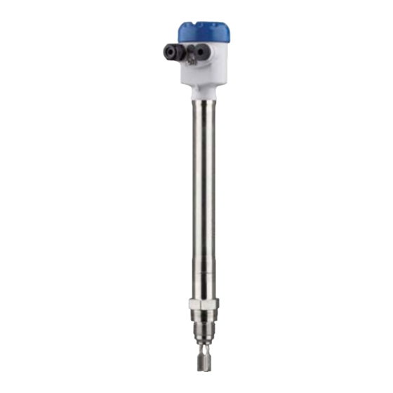
The OPTISWITCH 5300 C consists of the components: • Housing lid • Housing with electronics • Process fitting with tuning fork Fig. 1: OPTISWITCH 5300 C - compact version with plastic housing Housing lid Housing with electronics Temperature adapter 4 Process fitting OPTISWITCH 5300 C • Two-wire 8/16 mA... - Page 8 3 Product description Fig. 2: OPTISWITCH 5300 C with plastic housing and tube extension Housing lid Housing with electronics Temperature adapter 4 Process fitting Tube extension Type label The type label contains the most important data for identification and use of the instrument: • Article number • Serial number • Technical data •...
-
Page 9: Principle Of Operation
3 Product description Principle of operation Application area OPTISWITCH 5300 C is a point level sensor with tuning fork for point level detection. It is designed for industrial use in all areas of process technology and can be used in liquids. It is particularly suitable for applications with high temperatures up to 450 °C (842 °F) and high process pressure... -
Page 10: Storage And Transport
Plug connector For connecting the sensors with a separator to voltage supply or sig- nal processing, the sensors are also available with plug connectors. The following plug connectors are available: • M12 x 1 OPTISWITCH 5300 C • Two-wire 8/16 mA... - Page 11 3 Product description • ISO 4400 • Harting HAN 7D • Harting HAN 8D • Amphenol-Tuchel OPTISWITCH 5300 C • Two-wire 8/16 mA...
-
Page 12: Mounting
Switching point In general, OPTISWITCH 5300 C can be installed in any position. The instrument only has to be mounted in such a way that the tuning fork is at the height of the desired switching point. - Page 13 Switching point approx. 33 mm (1.3 in) Fig. 4: Horizontal mounting Switching point 2 Marking on top with threaded versions, marking aligned to flange holes with flange versions Fig. 5: Horizontal installation (recommended mounting position, particularly for adhesive products) Switching point Marking with screwed version, facing up In the case of flange versions, the fork is aligned as follows. OPTISWITCH 5300 C • Two-wire 8/16 mA...
- Page 14 Fig. 7: Measures against moisture ingress Caution: Transport Do not hold OPTISWITCH 5300 C on the tuning fork. Particularly with flange or tube versions, the tuning fork can be damaged just by the weight of the instrument. Transport coated instruments very carefully and avoid touching the tuning fork.
-
Page 15: Mounting Instructions
(1.16 in). To mount the sensor, proceed as follows: 1. Screw the OPTISWITCH 5300 C into the mounting boss up to the stop. You can determine the later position already before welding. 2. Mark the position of the OPTISWITCH 5300 C on the mounting boss. - Page 16 Information: The temperature adapter may be embedded in the vessel insulation only up to max. 50 mm (1.97 in). Only then is a reliable temperature decoupling guaranteed. OPTISWITCH 5300 C • Two-wire 8/16 mA...
- Page 17 Ambient temperature on the housing Inflowing medium If OPTISWITCH 5300 C is mounted in the filling stream, unwanted false measurement signals can be generated. For this reason, mount OPTISWITCH 5300 C at a position in the vessel where no distur- bances, e.g. from filling openings, agitators, etc., can occur. This applies particularly to instrument types with long extension tube. Fig. 9: Inflowing medium...
- Page 18 Extreme vibration caused by the process or the equipment, e.g. agitators or turbulence in the vessel, can cause a long extension tube of OPTISWITCH 5300 C to vibrate in resonance. This leads to increased stress on the upper weld joint. Should a longer tube version be necessary, you can provide a suitable support directly above the tuning fork to secure the extension tube.
-
Page 19: Connecting To Power Supply
EN 61326 for industrial areas, shielded cable should be used. Make sure that the cable used has the required temperature resist- ance and fire safety for max. occurring ambient temperature Use cable with round cross section for instruments with housing and cable gland. To ensure the seal effect of the cable gland (IP protection OPTISWITCH 5300 C • Two-wire 8/16 mA... -
Page 20: Connection Procedure
10. Screw the housing lid back on The electrical connection is finished. Wiring plan, single chamber housing The following illustrations apply to the non-Ex as well as to the Ex-d version. OPTISWITCH 5300 C • Two-wire 8/16 mA... - Page 21 5 Connecting to power supply Housing overview Fig. 11: Material versions, single chamber housing Plastic (not with Ex d) Aluminium Stainless steel, precision casting Stainless steel, electropolished (not with Ex d) Filter element for air pressure compensation OPTISWITCH 5300 C • Two-wire 8/16 mA...
- Page 22 Take note of the operating instructions manual of the controller. Suit- able controllers are listed in chapter " Technical data". If OPTISWITCH 5300 C is used in Ex areas, take note of the regula- tions in the safety instructions and conformity certificates. If the instrument is to be operated directly on the analogue input of a PLC, a suitable safety barrier should be connected.
- Page 23 5 Connecting to power supply Fig. 13: Wiring plan, single chamber housing Controller OPTISWITCH 5300 C • Two-wire 8/16 mA...
-
Page 24: Setup
WITCH 5300 C to " max.". Note: Always immerse the tuning fork of OPTISWITCH 5300 C in a liquid to test its function. Do not test the function of OPTISWITCH 5300 C with your hand. This can damage the sensor. -
Page 25: Adjustment Elements
• Yellow LED lights = 8 mA • Yellow LED off = 16 mA • Signal lamp (3) - Operat- Green LED lights = operating voltage on ing condition (green) OPTISWITCH 5300 C • Two-wire 8/16 mA... -
Page 26: Function Table
The following table provides an overview of the switching conditions depending on the set mode and the level. Note: Keep in mind that the mode switch of OPTISWITCH 5300 C must be always set to "max.". OPTISWITCH 5300 C • Two-wire 8/16 mA... -
Page 27: Proof Test (Whg, Sil)
2 Dismounting of the sensor and immersion in the original medium You can dismount the sensor for test purposes and check its proper functioning by immersing it in the original product. OPTISWITCH 5300 C • Two-wire 8/16 mA... - Page 28 Procedure 1. Carry out the function test according to the above description (1 Short interruption of the supply line to the sensor. OPTISWITCH 5300 C • Two-wire 8/16 mA...
- Page 29 Check if all three switching conditions change in the correct sequence and the specified duration. By doing so, you can check the function of the measuring system. You can find the test procedure under " Implementation - Function test". Make sure the connected downstream devices are activated dur- ing the function test. 2. Set the mode switch (min./max.) OPTISWITCH 5300 C • Two-wire 8/16 mA...
- Page 30 Pushing the test key An integrated test key is lowered in the front plate of the controller or in the electronics module of the OPTISWITCH 5300 C . Push the test key for > 2 seconds with a suitable object.
- Page 31 (±1.5 mA) 1.5 s (±0.5 s) 3. Full signal 16 mA currentless energized energized (±1.5 mA) 1.5 s (±0.5 s) 4. Return to current operating condition Starting time of the voltage supply OPTISWITCH 5300 C • Two-wire 8/16 mA...
- Page 32 Test passed Status Current value Time False signal < 3.6 mA 1.5 s (±0.5 s) Uncovered 8 mA (±1.5 mA) 1.5 s (±0.5 s) Covered 16 mA (±1.5 mA) 1.5 s (±0.5 s) OPTISWITCH 5300 C • Two-wire 8/16 mA...
-
Page 33: Maintenance And Fault Rectification
Check the vibrating element and the sensor for buildup ement and remove the buildup if there is any. Wrong mode selected Set the correct mode on the controller (overflow protec- tion, dry run protection). Wiring should be carried out according to the idle current principle. OPTISWITCH 5300 C • Two-wire 8/16 mA... -
Page 34: Exchanging The Electronics
You can find all the information you need to carry out an electronics exchange in the handbook of the new electronics module. How to proceed if a repair is necessary If it is necessary to repair the instrument, please contact the responsi- ble Krohne agency. OPTISWITCH 5300 C • Two-wire 8/16 mA... -
Page 35: Dismount
With Ex instruments, the housing cover may only be opened if there is no explosive atmosphere present. Disposal The device is made of recyclable materials. For this reason, it should be disposed of by a specialist recycling company. Observe the ap- plicable national regulations. OPTISWITCH 5300 C • Two-wire 8/16 mA... -
Page 36: Supplement
Ʋ Supporting material 316L Ʋ Material Ceramic Al (99.5 %) OPTISWITCH 5300 C • Two-wire 8/16 mA... - Page 37 Ʋ Mode max. Vibrating element uncovered: 8 mA ±1.5 mA, vibrating element covered: 16 mA ±1.5 mA Ʋ Fault message < 3.6 mA Modes (switchable) Min./Max. Depending on the mounting boss of the vessel. OPTISWITCH 5300 C • Two-wire 8/16 mA...
- Page 38 (0,029) (0,036) (0,043) (0,051) (0,058) (0,065) (0,072) (0,079) (0,087) Fig. 16: Influence of the product density on the switching point Shifting of the switching point in mm (in) Product density in g/cm³ (lb/in³) Switch position ≥ 0.47 g/cm³ (0.017 lb/in³) Switch position ≥ 0.7 g/cm³ (0.025 lb/in³) Switching point at reference conditions (notch) Tuning fork OPTISWITCH 5300 C • Two-wire 8/16 mA...
- Page 39 -1 … 100 bar/-100 … 10000 kPa (-14.5 … 1450 psig) (1450 psig) The process pressure is dependent on the process fit- ting, e.g. flange (see the following diagrams) Ʋ Instrument version up to 160 bar -1 … 160 bar/-100 … 16000 kPa (-14.5 … 2320 psig) (2320 psig) The process pressure is dependent on the process fit- ting, e.g. flange (see the following diagrams) OPTISWITCH 5300 C • Two-wire 8/16 mA...
- Page 40 Process temperature in °C (°F) Viscosity - dynamic 0.1 … 1000 mPa s (requirement: with density 1) Flow velocity max. 6 m/s (with a viscosity of 1000 mPa s) Density Ʋ Standard sensitivity 0.7 … 2.5 g/cm³ (0.025 … 0.09 lbs/in³) OPTISWITCH 5300 C • Two-wire 8/16 mA...
- Page 41 Ʋ ≥ 0.7 g/cm³ 0.7 … 2.5 g/cm³ (0.025 … 0.09 lbs/in³) Test key To activate the test process Voltage supply Operating voltage (via the signal condi- 9.6 … 35 V DC tioning instrument) Max. permissible process pressure: 25 bar (363 psig) OPTISWITCH 5300 C • Two-wire 8/16 mA...
-
Page 42: Dimensions
½ NPT M20x1,5/ ½ NPT Fig. 21: Housing versions in protection IP66/IP67 and IP66/IP68; 0.2 bar Plastic single chamber Stainless steel single chamber (electropolished) Stainless steel single chamber (precision casting) Aluminium - single chamber OPTISWITCH 5300 C • Two-wire 8/16 mA... - Page 43 OPTISWITCH 5300 C , compact version ø 33,7 mm (1.33") DN50 PN40 G 1, 1 NPT ø 28,5 mm ø 28,5 mm (1.12") (1.12") Fig. 22: OPTISWITCH 5300 C , compact version Sealing surface OPTISWITCH 5300 C • Two-wire 8/16 mA...
- Page 44 G 1, 1 NPT ø 21,3 mm (0.84") ø 28,5 mm ø 28,5 mm (1.12") (1.12") Fig. 23: OPTISWITCH 5300 C , tube version Sensor length - see Technical data - General data Sealing surface OPTISWITCH 5300 C • Two-wire 8/16 mA...
-
Page 45: Trademark
9 Supplement Trademark All the brands as well as trade and company names used are property of their lawful proprietor/ originator. OPTISWITCH 5300 C • Two-wire 8/16 mA... - Page 46 Notes OPTISWITCH 5300 C • Two-wire 8/16 mA...
- Page 47 Notes OPTISWITCH 5300 C • Two-wire 8/16 mA...
- Page 48 • Engineering, commissioning, calibration, maintenance and train- ing services Head Office KROHNE Messtechnick GmbH Ludwig-Krohne-Straße 5 47058 Duisburg (Germany) Tel.: +49 (0) 203 301 0 Tel.: +49 (0) 203 301 10389 info@krohne.de The current list of all KROHNE contacts and addresses can be found at: www.krohne.com...
Need help?
Do you have a question about the OPTISWITCH 5300 and is the answer not in the manual?
Questions and answers