KROHNE OPTISWITCH 5300 C Handbook
Vibrating level switch
Hide thumbs
Also See for OPTISWITCH 5300 C:
Table of Contents
Advertisement
Quick Links
Advertisement
Table of Contents

Related Manuals for KROHNE OPTISWITCH 5300 C


Summary of Contents for KROHNE OPTISWITCH 5300 C
- Page 1 OPTISWITCH 5300 C Handbook Vibrating Level Switch Relay...
-
Page 2: Table Of Contents
Exchanging the electronics .................... 25 How to proceed if a repair is necessary ................26 Dismount..........................27 Dismounting steps......................27 Disposal ......................... 27 Supplement ..........................28 Technical data ........................ 28 Dimensions ........................34 Trademark ........................37 Editing status: 2019-11-21 OPTISWITCH 5300 C • Relay... -
Page 3: About This Document
The dot set in front indicates a list with no implied sequence. Sequence of actions Numbers set in front indicate successive steps in a procedure. Battery disposal This symbol indicates special information about the disposal of bat- teries and accumulators. OPTISWITCH 5300 C • Relay... -
Page 4: For Your Safety
During work on and with the device, the required personal protective equipment must always be worn. Appropriate use The OPTISWITCH 5300 C is a sensor for point level detection. You can find detailed information about the area of application in chapter "Product description". Operational reliability is ensured only if the instrument is properly used according to the specifications in the operating instructions manual as well as possible supplementary instructions. -
Page 5: Safety Label On The Instrument
Canadian Electrical Code. Safety instructions for Ex areas For Ex applications, only devices with corresponding Ex approval may be used. Observe the Ex-specific safety instructions. These are an integral part of the operating instructions and are enclosed with every device with Ex approval. OPTISWITCH 5300 C • Relay... -
Page 6: Product Description
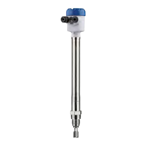
The OPTISWITCH 5300 C consists of the components: • Housing lid • Housing with electronics • Process fitting with tuning fork Fig. 1: OPTISWITCH 5300 C - compact version with plastic housing Housing lid Housing with electronics Temperature adapter 4 Process fitting OPTISWITCH 5300 C • Relay... - Page 7 3 Product description Fig. 2: OPTISWITCH 5300 C with plastic housing and tube extension Housing lid Housing with electronics Temperature adapter 4 Process fitting Tube extension Type label The type label contains the most important data for identification and use of the instrument: • Article number • Serial number • Technical data •...
-
Page 8: Principle Of Operation
3 Product description Principle of operation Application area OPTISWITCH 5300 C is a point level sensor with tuning fork for point level detection. It is designed for industrial use in all areas of process technology and can be used in liquids. It is particularly suitable for applications with high temperatures up to 450 °C (842 °F) and high process pressure... -
Page 9: Storage And Transport
DIN 2501, EN 1092-1, BS 10, ASME B 16.5, JIS B 2210-1984, GOST 12821-80. Electronics module The electronics module SW E60 is a replacement part for level switch- es OPTISWITCH 5300 C . You can find information in the operating instructions manual of the electronics module. Plug connector For connecting the sensors with a separator to voltage supply or sig- nal processing, the sensors are also available with plug connectors. - Page 10 3 Product description • ISO 4400 • Harting HAN 7D • Harting HAN 8D • Amphenol-Tuchel OPTISWITCH 5300 C • Relay...
-
Page 11: Mounting
DIN/EN/IEC/ANSI/ISA/UL/CSA 61010-1. Switching point In general, OPTISWITCH 5300 C can be installed in any position. The instrument only has to be mounted in such a way that the tuning fork is at the height of the desired switching point. - Page 12 (e.g. through cleaning processes) or on cooled or heated vessels. To maintain the housing protection, make sure that the housing lid is closed during operation and locked, if necessary. Make sure that the degree of contamination specified in chapter "Technical data" meets the existing ambient conditions. OPTISWITCH 5300 C • Relay...
-
Page 13: Mounting Instructions
4 Mounting Fig. 7: Measures against moisture ingress Caution: Transport Do not hold OPTISWITCH 5300 C on the tuning fork. Particularly with flange or tube versions, the tuning fork can be damaged just by the weight of the instrument. Transport coated instruments very carefully and avoid touching the tuning fork. Remove the packaging or the protective cover just before mounting. - Page 14 (1.16 in). To mount the sensor, proceed as follows: 1. Screw the OPTISWITCH 5300 C into the mounting boss up to the stop. You can determine the later position already before welding. 2. Mark the position of the OPTISWITCH 5300 C on the mounting boss.
- Page 15 Ambient temperature on the housing Inflowing medium If OPTISWITCH 5300 C is mounted in the filling stream, unwanted false measurement signals can be generated. For this reason, mount OPTISWITCH 5300 C at a position in the vessel where no distur- bances, e.g. from filling openings, agitators, etc., can occur. This applies particularly to instrument types with long extension tube. Fig. 9: Inflowing medium...
- Page 16 Extreme vibration caused by the process or the equipment, e.g. agitators or turbulence in the vessel, can cause a long extension tube of OPTISWITCH 5300 C to vibrate in resonance. This leads to increased stress on the upper weld joint. Should a longer tube version be necessary, you can provide a suitable support directly above the tuning fork to secure the extension tube.
-
Page 17: Connecting To Power Supply
6 … 12 mm (0.24 … 0.47 in) • 10 … 14 mm (0.40 … 0.55 in) Use a cable gland fitting the cable diameter. In hazardous areas, use only approved cable connections for OPTIS- WITCH 5300 C . Take note of the corresponding installation regulations for Ex applica- Connection cable tions. for Ex applications OPTISWITCH 5300 C • Relay... -
Page 18: Connection Procedure
9. Tighten the compression nut of the cable entry gland. The seal ring must completely encircle the cable 10. Screw the housing lid back on The electrical connection is finished. Wiring plan, single chamber housing The following illustrations apply to the non-Ex as well as to the Ex-d version. OPTISWITCH 5300 C • Relay... - Page 19 Control lamp - fault indication (red) Control lamp - Switching status (yellow) Control lamp - Operating status (green) Mode switch for selecting the switching behaviour (min./max.) DIL switch for sensitivity adjustment Ground terminal Connection terminals OPTISWITCH 5300 C • Relay...
- Page 20 5 Connecting to power supply Wiring plan - Relay output We recommend connecting OPTISWITCH 5300 C according to the closed-circuit principle, i.e. the switching circuit is open when there is a level signal, line break or fault (safe state). Information: The relays (2 x SPDT) are always shown in non-operative condition.
-
Page 21: Setup
DIL switch for adjustment of the density range (5) Note: Always immerse the tuning fork of OPTISWITCH 5300 C in a liquid to test its function. Do not test the function of OPTISWITCH 5300 C with your hand. This can damage the sensor. -
Page 22: Function Table
This can cause erroneous switchings. Function table The following table provides an overview of the switching conditions depending on the set mode and the level. OPTISWITCH 5300 C • Relay... - Page 23 Dry run protec- tion (6) (7) Relay energized Mode min. Dry run protec- tion (6) (7) Relay deener- gized Failure of the supply voltage (max./min. mode) (6) (7) Relay deener- gized Fault (6) (7) Relay deener- gized OPTISWITCH 5300 C • Relay...
-
Page 24: Maintenance And Fault Rectification
The operator of the system is responsible for taking suitable meas- tion occurs ures to rectify faults. Causes of malfunction The device offers maximum reliability. Nevertheless, faults can occur during operation. These may be caused by the following, e.g.: • Sensor • Process • Voltage supply • Signal processing The first measure to take is to check the output signal. In many cases, Fault rectification the causes can be determined this way and the faults quickly rectified. OPTISWITCH 5300 C • Relay... -
Page 25: Exchanging The Electronics
7 Maintenance and fault rectification Checking the switching signal Error Cause Rectification OPTISWITCH 5300 C signals "cov- Operating voltage too low Check operating voltage ered" without being submerged Electronics defective Press the mode switch. If the instru- (overflow protection) ment then changes the mode, the OPTISWITCH 5300 C signals "un-... -
Page 26: How To Proceed If A Repair Is Necessary
7 Maintenance and fault rectification How to proceed if a repair is necessary If it is necessary to repair the instrument, please contact the responsi- ble Krohne agency. OPTISWITCH 5300 C • Relay... -
Page 27: Dismount
Pass the instrument directly on to a specialised recycling company and do not use the municipal collecting points. If you have no way to dispose of the old instrument properly, please contact us concerning return and disposal. OPTISWITCH 5300 C • Relay... -
Page 28: Supplement
Ʋ Supporting material 316L Ʋ Material Ceramic Al (99.5 %) OPTISWITCH 5300 C • Relay... - Page 29 The contact is then no longer suitable for switching low-level signal circuits. Contact material (relay contacts) AgNi or AgSnO2 each with 3 µm gold plating Depending on the mounting boss of the vessel. OPTISWITCH 5300 C • Relay...
- Page 30 (0,014) (0,022) (0,029) (0,036) (0,043) (0,051) (0,058) (0,065) (0,072) (0,079) (0,087) Fig. 15: Influence of the product density on the switching point Shifting of the switching point in mm (in) Product density in g/cm³ (lb/in³) Switch position ≥ 0.47 g/cm³ (0.017 lb/in³) Switch position ≥ 0.7 g/cm³ (0.025 lb/in³) Switching point at reference conditions (notch) Tuning fork OPTISWITCH 5300 C • Relay...
- Page 31 -1 … 100 bar/-100 … 10000 kPa (-14.5 … 1450 psig) (1450 psig) The process pressure is dependent on the process fit- ting, e.g. flange (see the following diagrams) Ʋ Instrument version up to 160 bar -1 … 160 bar/-100 … 16000 kPa (-14.5 … 2320 psig) (2320 psig) The process pressure is dependent on the process fit- ting, e.g. flange (see the following diagrams) OPTISWITCH 5300 C • Relay...
- Page 32 Fig. 18: Process temperature - Process pressure - Version up to 160 bar (2321 psig) Process pressure in bar (psig) Process temperature in °C (°F) Process temperature (thread or flange temperature) Ʋ OPTISWITCH 5300 C of 316L/Al- -196 … +450 °C (-321 … +842 °F) loy C22 (2.4602)/Inconel 718 (2.4668) 70 °C (158 °F) 50 °C...
- Page 33 Min. detection or dry run protection Sensitivity switch Ʋ ≥ 0.47 g/cm³ 0.47 … 2.5 g/cm³ (0.017 … 0.09 lbs/in³) Ʋ ≥ 0.7 g/cm³ 0.7 … 2.5 g/cm³ (0.025 … 0.09 lbs/in³) Voltage supply Operating voltage 20 … 253 V AC, 50/60 Hz, 20 … 72 V DC Max. power consumption 3 VA (AC), 1 W (DC) Max. permissible process pressure: 25 bar (363 psig) OPTISWITCH 5300 C • Relay...
-
Page 34: Dimensions
Protection rating (IEC 61010-1) Approvals Depending on the version, instruments with approvals can have different technical data. For these instruments, please note the corresponding approval documents. They are included in the scope of delivery. Dimensions OPTISWITCH 5300 C , housing ~ 116 mm ~ 69 mm ~ 59 mm ~ 69 mm (4.57") (2.72") - Page 35 OPTISWITCH 5300 C , compact version ø 33,7 mm ø 33,7 mm (1.33") (1.33") DN50 PN40 G 1, 1 NPT ø 28,5 mm ø 28,5 mm (1.12") (1.12") Fig. 21: OPTISWITCH 5300 C , compact version Sealing surface OPTISWITCH 5300 C • Relay...
- Page 36 G 1, 1 NPT ø 21,3 mm (0.84") ø 28,5 mm ø 28,5 mm (1.12") (1.12") Fig. 22: OPTISWITCH 5300 C , tube version Sensor length - see Technical data - General data Sealing surface OPTISWITCH 5300 C • Relay...
-
Page 37: Trademark
9 Supplement Trademark All the brands as well as trade and company names used are property of their lawful proprietor/ originator. OPTISWITCH 5300 C • Relay... - Page 38 Notes OPTISWITCH 5300 C • Relay...
- Page 39 Notes OPTISWITCH 5300 C • Relay...
- Page 40 Products and systems for the oil and gas industry KROHNE Messtechnick GmbH & Co. KG Ludwig-Krohne-Straße 5 D-47058 Duisburg Tel.: +49 (0) 203 301 0 Tel.: +49 (0) 203 301 10389 info@krohne.de The current list of all KROHNE contacts and addresses can be found at: www.krohne.com...
Need help?
Do you have a question about the OPTISWITCH 5300 C and is the answer not in the manual?
Questions and answers