Table of Contents
Advertisement
Quick Links
Advertisement
Table of Contents

Related Manuals for KROHNE OPTISWITCH 5300


Summary of Contents for KROHNE OPTISWITCH 5300
- Page 1 OPTISWITCH 5300 C Handbook Vibrating Level Switch - two-wire...
-
Page 2: Table Of Contents
Maintenance ........................30 Rectify faults ........................30 Exchanging the electronics .................... 31 Instrument repair ......................31 Dismount Dismounting steps......................32 Disposal ......................... 32 Supplement Technical data ........................ 33 Dimensions ........................38 Editing status: 2015-11-10 OPTISWITCH 5300 C • - two-wire... -
Page 3: About This Document
This arrow indicates a single action. Sequence of actions Numbers set in front indicate successive steps in a procedure. Battery disposal This symbol indicates special information about the disposal of bat- teries and accumulators. OPTISWITCH 5300 C • - two-wire... -
Page 4: For Your Safety
During work on and with the device the required personal protective equipment must always be worn. Appropriate use The OPTISWITCH 5300 C is a sensor for point level detection. You can find detailed information about the area of application in chapter "Product description". Operational reliability is ensured only if the instrument is properly used according to the specifications in the operating instructions manual as well as possible supplementary instructions. -
Page 5: Safety Label On The Instrument
That is why we have introduced an environment management system with the goal of continuously improving company environmental pro- tection. The environment management system is certified according to DIN EN ISO 14001. Please help us fulfill this obligation by observing the environmental instructions in this manual: • Chapter "Packaging, transport and storage" • Chapter "Disposal" OPTISWITCH 5300 C • - two-wire... -
Page 6: Product Description
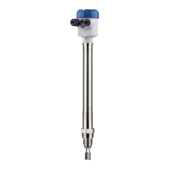
The OPTISWITCH 5300 C consists of the components: Constituent parts • Housing lid • Housing with electronics • Process fitting with tuning fork Fig. 1: OPTISWITCH 5300 C - compact version with plastic housing Housing lid Housing with electronics Temperature adapter 4 Process fitting OPTISWITCH 5300 C • - two-wire... - Page 7 3 Product description Fig. 2: OPTISWITCH 5300 C with plastic housing and tube extension Housing lid Housing with electronics Temperature adapter 4 Process fitting Tube extension The type label contains the most important data for identification and Type label use of the instrument: • Article number • Serial number • Technical data •...
-
Page 8: Principle Of Operation
3 Product description Principle of operation Application area OPTISWITCH 5300 C is a point level sensor with tuning fork for point level detection. It is designed for industrial use in all areas of process technology and can be used in liquids. It is particularly suitable for applications with high temperatures up to 450 °C (842 °F) and high process pressure... -
Page 9: Storage And Transport
For connecting the sensors with a separator to voltage supply or sig- nal processing, the sensors are also available with plug connectors. The following plug connectors are available: • M12 x 1 • ISO 4400 OPTISWITCH 5300 C • - two-wire... - Page 10 3 Product description • Harting HAN 7D • Harting HAN 8D • Amphenol-Tuchel OPTISWITCH 5300 C • - two-wire...
-
Page 11: Mounting
You can find the specifications in chapter "Technical data" and on the nameplate. Switching point In general, OPTISWITCH 5300 C can be installed in any position. The instrument only has to be mounted in such a way that the tuning fork is at the height of the desired switching point. - Page 12 Fig. 5: Horizontal installation (recommended mounting position, particularly for adhesive products) Switching point Marking with screwed version, facing up In the case of flange versions, the fork is aligned as follows. Fig. 6: Fork position with flange versions 1 Marking with flange version, facing up Moisture Use the recommended cables (see chapter "Connecting to power supply") and tighten the cable gland. OPTISWITCH 5300 C • - two-wire...
-
Page 13: Mounting Instructions
Fig. 7: Measures against moisture ingress Caution: Transport Do not hold OPTISWITCH 5300 C on the tuning fork. Particularly with flange or tube versions, the tuning fork can be damaged just by the weight of the instrument. Transport coated instruments very carefully and avoid touching the tuning fork. - Page 14 (1.16 in). To mount the sensor, proceed as follows: 1. Screw the OPTISWITCH 5300 C into the mounting boss up to the stop. You can determine the later position already before welding. 2. Mark the position of the OPTISWITCH 5300 C on the mounting boss.
- Page 15 Ambient temperature on the housing Inflowing medium If OPTISWITCH 5300 C is mounted in the filling stream, unwanted false measurement signals can be generated. For this reason, mount OPTISWITCH 5300 C at a position in the vessel where no distur- bances, e.g. from filling openings, agitators, etc., can occur. This applies particularly to instrument types with long extension tube. Fig. 9: Inflowing medium...
- Page 16 Extreme vibration caused by the process or the equipment, e.g. agitators or turbulence in the vessel, can cause a long extension tube of OPTISWITCH 5300 C to vibrate in resonance. This leads to increased stress on the upper weld joint. Should a longer tube version be necessary, you can provide a suitable support directly above the tuning fork to secure the extension tube.
-
Page 17: Connecting To Power Supply
Ex applications Cover all housing openings conforming to standard according to EN 60079-1. Connection procedure With Ex instruments, the housing cover may only be opened if there is no explosive atmosphere present. Proceed as follows: OPTISWITCH 5300 C • - two-wire... -
Page 18: Wiring Plan, Single Chamber Housing
The following illustrations apply to the non-Ex as well as to the Ex-d version. Housing overview Fig. 11: Material versions, single chamber housing Plastic (not with Ex d) Aluminium Stainless steel, precision casting Stainless steel, electropolished (not with Ex d) Filter element for air pressure compensation OPTISWITCH 5300 C • - two-wire... - Page 19 Suitable signal conditioning instruments are listed in chapter "Technical data". If OPTISWITCH 5300 C is used in Ex areas, take note of the regula- tions in the safety instructions and conformity certificates. If the instrument is to be operated directly on the analogue input of a PLC, a suitable safety barrier should be connected.
- Page 20 5 Connecting to power supply Fig. 13: Wiring plan, single chamber housing Signal conditioning instrument OPTISWITCH 5300 C • - two-wire...
-
Page 21: Setup
OPTISWITCH 5300 C to "max.". Note: Always immerse the tuning fork of OPTISWITCH 5300 C in a liquid to test its function. Do not test the function of OPTISWITCH 5300 C with your hand. This can damage the sensor. -
Page 22: Adjustment Elements
With the mode setting (4), the switching condition and hence the function of the signal lamp can be changed. • Yellow LED lights = 8 mA • Yellow LED off = 16 mA • Signal lamp (3) - Operat- Green LED lights = operating voltage on ing condition (green) OPTISWITCH 5300 C • - two-wire... -
Page 23: Function Chart
The test process will be carried out after releasing the key. Function chart The following chart provides an overview of the switching conditions depending on the set mode and the level. OPTISWITCH 5300 C • - two-wire... -
Page 24: Proof Test (Whg, Sil)
6 Setup Note: Keep in mind that the mode switch of OPTISWITCH 5300 C must be always set to "max.". Sensor Signal con- ditioning instrument Mode on the Level Signal cur- Signal lamp - Signal lamp - Signal lamp Analogue... - Page 25 By doing so, you can check the function of the measuring system. If this is not the case, then there is a fault in the measuring sys- tem. Make sure the connected downstream devices are activated dur- ing the function test. OPTISWITCH 5300 C • - two-wire...
- Page 26 Short interruption of the supply line to the sensor You can carry out the function test with the outputted current values also directly via a safety PLC or a process control system. 1. Separate the instrument briefly (>2 s) from voltage supply. OPTISWITCH 5300 C • - two-wire...
- Page 27 Push the test key for > 2 seconds with a suitable object (screwdriver, pen, etc.). When the OPTISWITCH 5300 C is connected to a processing system or an SPLC, you have to interrupt the connection cable to the sensor for >...
- Page 28 1. Fault sig- < 3.6 mA currentless currentless currentless approx. 1.5 s 2. Empty approx. energized currentless energized signal 8 mA (approx. 1.5 s) Starting time of the voltage supply OPTISWITCH 5300 C • - two-wire...
- Page 29 Note: When used as overfill protection according to WHG and use in meas- uring chains according IEC 61508, mode B is not permitted. Test assessment (SPLC) Test passed • Interference signal (< 3.6 mA) ≥ 400 ms • Uncovered (approx. 8 mA) ≥ 1 s • Covered (approx. 16 mA) ≥ 1 s Test not passed • Interference signal (< 3.6 mA) < 400 ms / ≥ 750 ms • Uncovered (approx. 8 mA) < 1 s / ≥ 2 s • Covered (approx. 16 mA) < 1 s / ≥ 2 s OPTISWITCH 5300 C • - two-wire...
-
Page 30: Maintenance And Fault Rectification
Error on the vibrating el- Check if the vibrating element is damaged or extreme- ement ly corroded. Interference on the elec- Exchanging the electronics module tronics module instrument defective Exchange the instrument or send it in for repair OPTISWITCH 5300 C • - two-wire... -
Page 31: Exchanging The Electronics
By doing this you help us carry out the repair quickly and without hav- ing to call back for needed information. • Print and fill out one form per instrument • Clean the instrument and pack it damage-proof • Attach the completed form and possibly also a safety data sheet to the instrument OPTISWITCH 5300 C • - two-wire... -
Page 32: Dismount
WEEE directive. Correct disposal avoids negative effects on humans and the environ- ment and ensures recycling of useful raw materials. Materials: see chapter "Technical data" If you have no way to dispose of the old instrument properly, please contact us concerning return and disposal. OPTISWITCH 5300 C • - two-wire... -
Page 33: Supplement
(99.5 %) Ʋ Contacts Kovar (gold-plated) Ʋ Helium leak rate < 10 mbar l/s Ʋ Pressure resistance PN 160 Sensor length - Compact version Ʋ Alloy C22 (2.4602) 74 mm (2.91 in) or gas-tight leadthrough OPTISWITCH 5300 C • - two-wire... - Page 34 Ʋ Product density 1 g/cm³ (0.036 lbs/in³) (water) Ʋ Product viscosity 1 mPa s Ʋ Superimposed pressure 0 kPa Ʋ Sensor installation Vertically from top Ʋ Density selection switch ≥ 0.7 g/cm³ Depending on the mounting boss of the vessel. OPTISWITCH 5300 C • - two-wire...
- Page 35 -8 (-0.31") -10 (-0.39") (290) (580) (870) (1160) (1450) (1740) (2030) (2320) Fig. 49: Influence of the process pressure to the switching point Shifting of the switching point in mm (in) Process pressure in bar (psig) Switching point at reference conditions (notch) Tuning fork OPTISWITCH 5300 C • - two-wire...
- Page 36 Fig. 51: Process temperature - Process pressure - Version up to 160 bar (2321 psig) Process pressure in bar (psig) Process temperature in °C (°F) Process temperature (thread or flange temperature) Ʋ OPTISWITCH 5300 C of 316L/Alloy -196 … +450 °C (-321 … +842 °F) C22 (2.4602)/Inconel 718 (2.4668) OPTISWITCH 5300 C • - two-wire...
- Page 37 Min. detection or dry run protection Max. permissible process pressure: 25 bar (363 psig)/not in safety-instrumented systems (SIL)/not in WHG applications. Depending on the version M12 x 1, according to ISO 4400, Harting, 7/8" FF. OPTISWITCH 5300 C • - two-wire...
-
Page 38: Dimensions
Fig. 53: Housing versions in protection IP 66/IP 67 and IP 66/IP 68; 0.2 bar Plastic housing Stainless steel housing, electropolished Stainless steel housing, precision casting Aluminium housing A suitable cable is required for maintaining the protection rating. OPTISWITCH 5300 C • - two-wire... - Page 39 9 Supplement OPTISWITCH 5300 C , compact version ø 33,7 mm ø 33,7 mm (1.33") (1.33") DN50 PN40 G 1, 1 NPT Fig. 54: OPTISWITCH 5300 C , compact version Sealing surface OPTISWITCH 5300 C • - two-wire...
- Page 40 G 1, 1 NPT ø 21,3 mm (0.84") ø 29,2 mm ø 29,2 mm (1.15") (1.15") Fig. 55: OPTISWITCH 5300 C , tube version Sensor length - see Technical data - General data Sealing surface OPTISWITCH 5300 C • - two-wire...
- Page 41 9 Supplement Trademark All the brands as well as trade and company names used are property of their lawful proprietor/ originator. OPTISWITCH 5300 C • - two-wire...
- Page 42 Notes OPTISWITCH 5300 C • - two-wire...
- Page 43 Notes OPTISWITCH 5300 C • - two-wire...
- Page 44 Products and systems for the oil and gas industry • KROHNE Messtechnick GmbH & Co. KG Ludwig-Krohne-Straße 5 D-47058 Duisburg Tel.: +49 (0) 203 301 0 Tel.: +49 (0) 203 301 10389 info@krohne.de The current list of all KROHNE contacts and addresses can be found at: www.krohne.com...
Need help?
Do you have a question about the OPTISWITCH 5300 and is the answer not in the manual?
Questions and answers