KROHNE OPTISWITCH 5200 C Operating Instructions Manual
With two-wire output
Hide thumbs
Also See for OPTISWITCH 5200 C:
- Operating instructions book manual (45 pages) ,
- Handbook (44 pages) ,
- Operating instructions manual (16 pages)
Table of Contents
Advertisement
Quick Links
Advertisement
Table of Contents

Related Manuals for KROHNE OPTISWITCH 5200 C


Summary of Contents for KROHNE OPTISWITCH 5200 C
- Page 1 Operating Instructions OPTISWITCH 5200 C, 5250 C with two-wire output...
-
Page 2: Table Of Contents
Dismounting procedure ....Disposal ......OPTISWITCH 5200 C, 5250 C - with two-wire output... - Page 3 Technical data......Dimensions ......OPTISWITCH 5200 C, 5250 C - with two-wire output...
-
Page 4: About This Document
The dot set in front indicates a list with no implied sequence. à Action This arrow indicates a single action. Sequence Numbers set in front indicate successive steps in a procedure. OPTISWITCH 5200 C, 5250 C - with two-wire output... -
Page 5: For Your Safety
2.2 Appropriate use OPTISWITCH 5200 C, 5250 C is a sensor for level detection. Detailed information on the application range of OPTISWITCH 5200 C, 5250 C is available in chapter "Product description". -
Page 6: Sil Conformity
For your safety 2.6 SIL conformity OPTISWITCH 5200 C, 5250 C fulfills the requirements of functional safety according to IEC 61508/IEC 61511. You can find further information in the supplementary instructions manual "Safety Manual - Functional safety (SIL) OPTISWITCH 5XXX". -
Page 7: Product Description
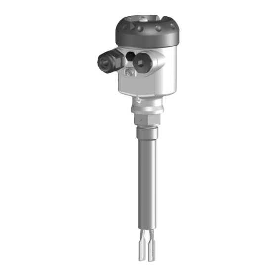
Fig. 1: OPTISWITCH 5200 C, 5250 C with plastic housing Housing cover Housing with electronics Process fitting 3.2 Principle of operation OPTISWITCH 5200 C, 5250 C is a level sensor with tuning Area of application fork for level detection. OPTISWITCH 5200 C, 5250 C - with two-wire output... - Page 8 Typical applications are overfill and dry run protection. With a tuning fork of only 40 mm length, OPTISWITCH 5200 C, 5250 C can be also mounted, e.g. in pipelines from DN 25. The small tuning fork allows use in vessels, tanks and pipes.
-
Page 9: Operation
Product description 3.3 Operation The switching condition of OPTISWITCH 5200 C, 5250 C with plastic housing can be checked when the housing is closed (signal lamp). With the basic setting, products with a density >0.7 g/cm³ (>0.025 lbs/in³) can be detected. The instrument can be adapted if products with lower density should be measured. -
Page 10: Mounting
Mounting 4 Mounting 4.1 General instructions In general, OPTISWITCH 5200 C, 5250 C can be mounted in Switching point any position. The instrument must be mounted in such a way that the tuning fork is at the height of the requested switching point. - Page 11 Use the recommended cables (see chapter "Connecting to Moisture power supply") and tighten the cable gland. You can give your OPTISWITCH 5200 C, 5250 C additional protection against moisture penetration by leading the con- nection cable downward in front of the cable entry. Rain and...
- Page 12 (e.g. by cleaning processes) or on cooled or heated vessels. Fig. 6: Measures against moisture penetration Do not hold OPTISWITCH 5200 C, 5250 C on the tuning fork. Transport Particularly with flange or tube versions, the tuning fork can be damaged by the instrument weight.
-
Page 13: Mounting Instructions
OPTISWITCH 5200 C, 5250 C has a defined thread starting Welded socket point. This means that every OPTISWITCH 5200 C, 5250 C is in the same fork position after being screwed in. Remove therefore the supplied seal from the thread of OPTISWITCH 5200 C, 5250 C. - Page 14 For that reason, sockets for flanges and mounting bosses should be avoided when mounting horizontally. If OPTISWITCH 5200 C, 5250 C is mounted in the filling Inflowing medium stream, unwanted switching signals may be generated. Mount OPTISWITCH 5200 C, 5250 C at a location in the vessel where no disturbing influence from e.g.
- Page 15 This measure applies particularly to applications in Ex areas category 1G or WHG. Make sure that the tube is not bent by this measure. Fig. 9: Lateral straining of OPTISWITCH 5200 C, 5250 C Instruments with enamel coating should be treated very Enamel coating carefully and shocks should be avoided.
-
Page 16: Connecting To Voltage Supply
Select power supply Take note of the general installation regulations. As a rule, connect OPTISWITCH 5200 C, 5250 C to vessel ground (PA), or in case of plastic vessels, to the next ground potential. On the side of the instrument housing there is a ground terminal between the cable entries. -
Page 17: Wiring Plan, Single Chamber Housing
EEx d version. Housing overview Fig. 10: Material versions, single chamber housing Plastic (not with EEx d) Aluminium Stainless steel (not with EEx d) Filter element for pressure compensation (not with EEx d) OPTISWITCH 5200 C, 5250 C - with two-wire output... - Page 18 Suitable signal conditioning instru- ments are listed in the Technical data. If OPTISWITCH 5200 C, 5250 C is used in Ex areas as part of an overfill protection system acc. to WHG, take note for the regulations in the safety instructions and conformity certifi-...
- Page 19 If OPTISWITCH with oscillator SW E60Z EX, SW E60Z EX E1 should be operated directly on the analogue input of a PLC, a suitable safety barrier should be connected. Fig. 12: Wiring plan, single chamber housing OPTISWITCH 5200 C, 5250 C - with two-wire output...
-
Page 20: Set Up
For test purposes, immerse the tuning fork of OPTISWITCH 5200 C, 5250 C always in liquids. Do not test the function of OPTISWITCH 5200 C, 5250 C with the hand. This can damage the sensor. OPTISWITCH 5200 C, 5250 C - with two-wire output... -
Page 21: Adjustment Elements
6.3 Function chart The following chart provides an overview of the switching conditions depending on the adjusted mode and level. OPTISWITCH 5200 C, 5250 C - with two-wire output... -
Page 22: Recurring Test And Function Test
5200 C, 5250 C Ex is used as part of an overfill protection system according to WHG. OPTISWITCH 5200 C, 5250 C Ex in conjunction with an SU 501 (Ex) is qualified in mode A (overfill protection) for use in measuring chains of SIL2 acc. - Page 23 The sensor must neither be removed nor must a response be triggered by filling the vessel. This applies to OPTISWITCH 5200 C, 5250 C with two-wire oscillator SW E60Z EX. If you are subject to the WHG regulations, you can carry out the function test with the outputted current values also directly via a PLC or a process control system.
- Page 24 WHG and use in measuring chains acc. to IEC 61508. You can carry out the function test with the outputted current values also directly with a PLC or a process control system (WHG). OPTISWITCH 5200 C, 5250 C - with two-wire output...
-
Page 25: Maintenance And Fault Rectification
Fault rectification many cases, the causes can be determined this way and the faults rectified. OPTISWITCH 5200 C, 5250 C signals "covered" when the Checking the switching signal vibrating element is not submerged (overfill protection) OPTISWITCH 5200 C, 5250 C signals "uncovered" when... -
Page 26: Instrument Repair
Print and fill out one form per instrument Clean the instrument and pack it damage-proof Attach the completed form and possibly also a safety data sheet to the instrument OPTISWITCH 5200 C, 5250 C - with two-wire output... -
Page 27: Dismounting
Correct disposal avoids negative effects to persons and environment and ensures recycling of useful raw materials. Materials: see "Technical data" If you cannot dispose of the instrument properly, please contact us about disposal methods or return. OPTISWITCH 5200 C, 5250 C - with two-wire output... - Page 28 Weights - Plastic housing 760 g (27 oz) - Aluminium housing 1170 g (41 oz) - Stainless steel housing 1530 g (54 oz) - Tube extension approx. 110 g/m (1.2 oz/ft) OPTISWITCH 5200 C, 5250 C - with two-wire output...
- Page 29 Max. detection or overflow/overfill protection Min. detection or dry run protection Measuring accuracy Hysteresis approx. 2 mm (0.08 in) with vertical installation Integration time approx. 500 ms Frequency approx. 1200 Hz OPTISWITCH 5200 C, 5250 C - with two-wire output...
- Page 30 Fig. 14: Ambient temperature - Product temperature Product temperature Ambient temperature Temperature range with temperature adapter Viscosity - dynamic 0.1 … 10,000 mPa s (requirement: with density Density 0.7 … 2.5 g/cm³ (0.025 … 0.09 lbs/in³); OPTISWITCH 5200 C, 5250 C - with two-wire output...
- Page 31 Overfill protection acc. to WHG Ship approvals Depending on the version M12x1, according to DIN 43650, Harting, Am- phenol-Tuchel, 7/8" FF. Deviating data in Ex applications: see separate safety instructions. Only with Aluminium housing. OPTISWITCH 5200 C, 5250 C - with two-wire output...
- Page 32 ") ") ø 77mm ") ø 84mm ø 77mm ") ") ") M20x1,5/ M20x1,5/ M20x1,5 ½ NPT ½ ½ NPT Fig. 15: Housing versions Plastic housing Stainless steel housing Aluminium housing OPTISWITCH 5200 C, 5250 C - with two-wire output...
- Page 33 OPTISWITCH 5200 C, 5250 C 32 (G "NPT) 41 (G1A, 1"NPT) "NPT G1A, 1"NPT ø33,7mm ") Fig. 16: OPTISWITCH 5200 C, 5250 C, threaded version Thread Tri-Clamp Cone DN 25 Bolting DN 40 Flange Gas-tight leadthrough Temperature adapter = Sensor length, see "Technical data"...
- Page 34 Supplement OPTISWITCH 5200 C, 5250 C - with two-wire output...
- Page 35 Supplement OPTISWITCH 5200 C, 5250 C - with two-wire output...
- Page 36 Subject to change without notice 30435-EN-060831...
Need help?
Do you have a question about the OPTISWITCH 5200 C and is the answer not in the manual?
Questions and answers