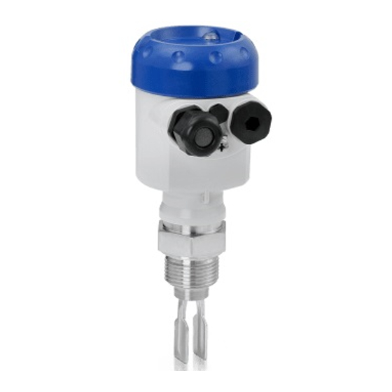
KROHNE OPTISWITCH 5100 C Handbook
Vibrating level switch, two-wire 8/16 ma
Hide thumbs
Also See for OPTISWITCH 5100 C:
- Manual (40 pages) ,
- Handbook (36 pages) ,
- Operating instructions manual (16 pages)
Table of Contents
Advertisement
Quick Links
Advertisement
Table of Contents

Related Manuals for KROHNE OPTISWITCH 5100 C


Summary of Contents for KROHNE OPTISWITCH 5100 C
- Page 1 OPTISWITCH 5100 C, 5150 C Handbook Vibrating Level Switch Two-wire 8/16 mA...
-
Page 2: Table Of Contents
How to proceed if a repair is necessary ................28 Dismount..........................29 Dismounting steps......................29 Disposal ......................... 29 Supplement ..........................30 Technical data ........................ 30 Dimensions ........................37 Trademark ........................40 OPTISWITCH 5100 C, 5150 C • Two-wire 8/16 mA... - Page 3 Contents Editing status: 2019-11-21 OPTISWITCH 5100 C, 5150 C • Two-wire 8/16 mA...
-
Page 4: About This Document
The dot set in front indicates a list with no implied sequence. Sequence of actions Numbers set in front indicate successive steps in a procedure. Battery disposal This symbol indicates special information about the disposal of bat- teries and accumulators. OPTISWITCH 5100 C, 5150 C • Two-wire 8/16 mA... -
Page 5: For Your Safety
During work on and with the device, the required personal protective equipment must always be worn. Appropriate use The OPTISWITCH 5100 C, 5150 C is a sensor for point level detec- tion. You can find detailed information about the area of application in chapter "Product description". Operational reliability is ensured only if the instrument is properly used according to the specifications in the operating instructions manual as well as possible supplementary instructions. -
Page 6: Safety Label On The Instrument
Safety instructions for Ex areas For Ex applications, only devices with corresponding Ex approval may be used. Observe the Ex-specific safety instructions. These are an integral part of the operating instructions and are enclosed with every device with Ex approval. OPTISWITCH 5100 C, 5150 C • Two-wire 8/16 mA... -
Page 7: Product Description
Principle of operation Application area OPTISWITCH 5100 C, 5150 C is a point level sensor with tuning fork for point level detection. It is designed for industrial use in all areas of process technology and can be used in liquids. -
Page 8: Adjustment
3 Product description Typical applications are overfill and dry run protection. With its tuning fork of only 40 mm length, OPTISWITCH 5100 C, 5150 C can also be mounted e.g. in pipelines from DN 32. The small tuning fork allows use in vessels, tanks and pipes. Thanks to its simple and robust measuring system, OPTISWITCH 5100 C, 5150 C is virtually unaf- fected by the chemical and physical properties of the liquid. -
Page 9: Accessories
The following plug connectors are available: • M12 x 1 • ISO 4400 • Harting HAN 7D • Harting HAN 8D • Amphenol-Tuchel OPTISWITCH 5100 C, 5150 C • Two-wire 8/16 mA... -
Page 10: Mounting
DIN/EN/IEC/ANSI/ISA/UL/CSA 61010-1. Switching point In general, OPTISWITCH 5100 C, 5150 C can be installed in any position. The instrument only has to be mounted in such a way that the tuning fork is at the height of the desired switching point. - Page 11 Fig. 3: Horizontal mounting Switching point Marking with screwed version, facing up Fig. 4: Horizontal installation (recommended mounting position, particularly for adhesive products) Switching point Marking with screwed version, facing up In the case of flange versions, the fork is aligned as follows. OPTISWITCH 5100 C, 5150 C • Two-wire 8/16 mA...
- Page 12 "Technical data" meets the existing ambient conditions. Fig. 6: Measures against moisture ingress Caution: Transport Do not hold OPTISWITCH 5100 C, 5150 C on the tuning fork. Particu- larly with flange or tube versions, the tuning fork can be damaged just by the weight of the instrument. Transport coated instruments very carefully and avoid touching the tuning fork.
-
Page 13: Mounting Instructions
This means that every OPTISWITCH 5100 C, 5150 C is in the same fork position after being screwed in. Remove therefore the supplied seal from the thread of OPTISWITCH 5100 C, 5150 C. This seal is not required when using a welded socket with O-ring in front. - Page 14 Inflowing medium If OPTISWITCH 5100 C, 5150 C is mounted in the filling stream, un- wanted false measurement signals can be generated. For this reason, mount OPTISWITCH 5100 C, 5150 C at a position in the vessel where no disturbances, e.g. from filling openings, agitators, etc., can occur. Product flow To make sure the tuning fork of OPTISWITCH 5100 C, 5150 C gener- ates as little resistance as possible to product flow, mount the sensor so that the surfaces are parallel to the product movement.
-
Page 15: Connecting To Power Supply
Cover all housing openings conforming to standard according to EN 60079-1. Connection procedure With Ex instruments, the housing cover may only be opened if there is no explosive atmosphere present. Proceed as follows: 1. Unscrew the housing lid OPTISWITCH 5100 C, 5150 C • Two-wire 8/16 mA... -
Page 16: Wiring Plan, Single Chamber Housing
Fig. 8: Material versions, single chamber housing Plastic (not with Ex d) Aluminium Stainless steel, precision casting Stainless steel, electropolished (not with Ex d) Filter element for pressure compensation (not with Ex d) OPTISWITCH 5100 C, 5150 C • Two-wire 8/16 mA... - Page 17 Take note of the operating instructions manual of the controller. Suit- able controllers are listed in chapter "Technical data". If OPTISWITCH 5100 C, 5150 C is used in Ex areas as part of an overfill protection system according to WHG (Water Resources Act), take note of the regulations in the safety instructions and conformity certificates. If the instrument with electronics module SWE60Z EX,...
- Page 18 5 Connecting to power supply Fig. 10: Wiring plan, single chamber housing OPTISWITCH 5100 C, 5150 C • Two-wire 8/16 mA...
-
Page 19: Setup
The switching delay can also be modified on the controller. Note: Always immerse the tuning fork of OPTISWITCH 5100 C, 5150 C in a liquid to test its function. Do not test the function of OPTISWITCH 5100 C, 5150 C with your hand. This can damage the sensor. -
Page 20: Function Table
< 21 mA protection Mode B approx. > 12.5 mA 16 mA Dry run < 21 mA protection Mode B approx. > 3.8 mA 8 mA Dry run < 11.5 mA protection Green OPTISWITCH 5100 C, 5150 C • Two-wire 8/16 mA... -
Page 21: Proof Test (Whg, Sil)
WHG. The implementation of the proof test according to WHG is stipulated in the general type approval, item 8. Take note of these higher-ranking approvals if OPTISWITCH 5100 C, 5150 C Ex is used as part of an overfill protection system according to WHG. The following instrument combinations meet the requirements ac-... - Page 22 Procedure 1. Carry out the function test according to the above description (1 Short interruption of the supply line to the sensor. Separate the instrument briefly (> 2 s) from voltage supply or push the test key. OPTISWITCH 5100 C, 5150 C • Two-wire 8/16 mA...
- Page 23 Check if the switching status changes (signal lamp - switching status). By doing so, you can check the function of the measuring system. If this is not the case, then there is a fault in the measuring sys- tem. OPTISWITCH 5100 C, 5150 C • Two-wire 8/16 mA...
- Page 24 Pushing the test key An integrated test key is lowered in the front plate of the controller or in the electronics module of the OPTISWITCH 5100 C, 5150 C. Push the test key for > 2 seconds with a suitable object.
- Page 25 Push the test key for > 2 seconds with a suitable object (screwdriver, pen, etc.). When the OPTISWITCH 5100 C, 5150 C is connected to a process- ing system or an SPLC, you have to interrupt the connection cable to the sensor for >...
- Page 26 < 3.6 mA 0.6 s (±0.2 s) Uncovered 8 mA (±1.5 mA) 1.5 s (±0.5 s) Covered 16 mA (±1.5 mA) 1.5 s (±0.5 s) Starting time of the voltage supply OPTISWITCH 5100 C, 5150 C • Two-wire 8/16 mA...
-
Page 27: Maintenance And Fault Rectification
Check the vibrating element and the sensor for buildup ement and remove the buildup if there is any. Wrong mode selected Set the correct mode on the controller (overflow protec- tion, dry run protection). Wiring should be carried out according to the idle current principle. OPTISWITCH 5100 C, 5150 C • Two-wire 8/16 mA... -
Page 28: Exchanging The Electronics
These electronics modules are called SW60E or SW60E1. How to proceed if a repair is necessary If it is necessary to repair the instrument, please contact the responsi- ble Krohne agency. OPTISWITCH 5100 C, 5150 C • Two-wire 8/16 mA... -
Page 29: Dismount
Pass the instrument directly on to a specialised recycling company and do not use the municipal collecting points. If you have no way to dispose of the old instrument properly, please contact us concerning return and disposal. OPTISWITCH 5100 C, 5150 C • Two-wire 8/16 mA... -
Page 30: Supplement
Ʋ Supporting material 316L OPTISWITCH 5100 C, 5150 C • Two-wire 8/16 mA... - Page 31 Ʋ Helium leak rate < 10 mbar l/s Ʋ Pressure resistance PN 64 Sensor length Ʋ Length OPTISWITCH 5100 C, 5150 C See chapter "Dimensions" Instrument weight (depending on pro- 0.8 … 4 kg (0.18 … 8.82 lbs) cess fitting) Layer thickness Ʋ Enamel 600 µm ±200 µm (0.024 in ±0.008 in)
- Page 32 (32 °F) (122 °F) (212 °F) (302 °F) (392 °F) Fig. 13: Influence of the process temperature on the switching point Shifting of the switching point in mm (in) Process temperature in °C (°F) Switching point at reference conditions (notch) Tuning fork OPTISWITCH 5100 C, 5150 C • Two-wire 8/16 mA...
- Page 33 Process pressure in bar (psig) Switching point at reference conditions (notch) Tuning fork Non-repeatability 0.1 mm (0.004 in) Hysteresis approx. 2 mm (0.08 in) with vertical installation Switching delay approx. 500 ms (on/off) Measuring frequency approx. 1200 Hz OPTISWITCH 5100 C, 5150 C • Two-wire 8/16 mA...
- Page 34 (212 °F) (302 °F) (482 °F) -40 °C (-40 °F) Fig. 16: Ambient temperature - Process temperature Process temperature in °C (°F) Ambient temperature in °C (°F) Temperature range with temperature adapter OPTISWITCH 5100 C, 5150 C • Two-wire 8/16 mA...
- Page 35 Density Ʋ Standard sensitivity 0.7 … 2.5 g/cm³ (0.025 … 0.09 lbs/in³) Ʋ High sensitivity 0.5 … 2.5 g/cm³ (0.018 … 0.09 lbs/in³) Vibration resistance Ʋ Instrument housing 1 g at 5 … 200 Hz according to EN 60068-2-6 (vibration with resonance) Ʋ Sensor 1 g with 5 … 200 Hz according EN 60068-2-6 (vibration at resonance) with sensor length up to 50 cm (19.69 in) OPTISWITCH 5100 C, 5150 C • Two-wire 8/16 mA...
- Page 36 Ʋ Ex-ia instrument (FM, CSA) 12 … 31 V DC Electrical protective measures Protection rating IP66/IP67 acc. to IEC 60529, Type 4X acc. to NEMA Protection class Approvals Depending on the version, instruments with approvals can have different technical data. For these instruments, please note the corresponding approval documents. They are included in the scope of delivery. OPTISWITCH 5100 C, 5150 C • Two-wire 8/16 mA...
-
Page 37: Dimensions
(3.31") M20x1,5 M20x1,5/ M20x1,5/ M20x1,5/ ½ NPT ½ NPT ½ NPT M20x1,5/ ½ NPT Fig. 19: Housing versions Plastic housing Stainless steel housing (electropolished) Stainless steel housing (precision casting) Aluminium housing OPTISWITCH 5100 C, 5150 C • Two-wire 8/16 mA... - Page 38 32 (G¾A, ¾"NPT) 41 (G1A, 1"NPT) G¾A, ¾"NPT G1A, 1"NPT ø 33,7 mm (1.33") Fig. 20: OPTISWITCH 5100 C, 5150 C Thread Clamp Cone DN 25 Slotted nut DN 40 Flange Tuchenhagen Varivent OPTISWITCH 5100 C, 5150 C • Two-wire 8/16 mA...
- Page 39 9 Supplement OPTISWITCH 5100 C, 5150 C, options Fig. 21: Options Gas-tight leadthrough Temperature adapter OPTISWITCH 5100 C, 5150 C • Two-wire 8/16 mA...
-
Page 40: Trademark
9 Supplement Trademark All the brands as well as trade and company names used are property of their lawful proprietor/ originator. OPTISWITCH 5100 C, 5150 C • Two-wire 8/16 mA... - Page 41 Notes OPTISWITCH 5100 C, 5150 C • Two-wire 8/16 mA...
- Page 42 Notes OPTISWITCH 5100 C, 5150 C • Two-wire 8/16 mA...
- Page 43 Notes OPTISWITCH 5100 C, 5150 C • Two-wire 8/16 mA...
- Page 44 Products and systems for the oil and gas industry KROHNE Messtechnick GmbH & Co. KG Ludwig-Krohne-Straße 5 D-47058 Duisburg Tel.: +49 (0) 203 301 0 Tel.: +49 (0) 203 301 10389 info@krohne.de The current list of all KROHNE contacts and addresses can be found at: www.krohne.com...
Need help?
Do you have a question about the OPTISWITCH 5100 C and is the answer not in the manual?
Questions and answers
i am working doha west power station kuwait,i want to purchaes KROHNE make 5100c level switch.i need ordering information details