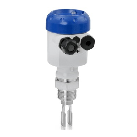
KROHNE OPTISWITCH 5100 C Handbook
Vibrating level switch
Hide thumbs
Also See for OPTISWITCH 5100 C:
- Handbook (44 pages) ,
- Manual (40 pages) ,
- Operating instructions manual (16 pages)
Table of Contents
Advertisement
Quick Links
Advertisement
Table of Contents

Related Manuals for KROHNE OPTISWITCH 5100 C


Summary of Contents for KROHNE OPTISWITCH 5100 C
- Page 1 OPTISWITCH 5100 C, 5150 C Handbook Vibrating Level Switch Relay (DPDT)
-
Page 2: Table Of Contents
Rectify faults ........................21 Exchanging the electronics .................... 22 Instrument repair ......................22 Dismount Dismounting steps......................23 Disposal ......................... 23 Supplement Technical data ........................ 24 Dimensions ........................31 Trademark ........................34 Editing status: 2016-11-18 OPTISWITCH 5100 C, 5150 C • Relay (DPDT) -
Page 3: About This Document
This arrow indicates a single action. Sequence of actions Numbers set in front indicate successive steps in a procedure. Battery disposal This symbol indicates special information about the disposal of bat- teries and accumulators. OPTISWITCH 5100 C, 5150 C • Relay (DPDT) -
Page 4: For Your Safety
During work on and with the device the required personal protective equipment must always be worn. Appropriate use The OPTISWITCH 5100 C, 5150 C is a sensor for point level detec- tion. You can find detailed information about the area of application in chapter "Product description". Operational reliability is ensured only if the instrument is properly used according to the specifications in the operating instructions manual as well as possible supplementary instructions. -
Page 5: Safety Label On The Instrument
Safety Manual "OPTISWITCH 5XXX". Safety instructions for Ex areas Please note the Ex-specific safety information for installation and op- eration in Ex areas. These safety instructions are part of the operating instructions manual and come with the Ex-approved instruments. OPTISWITCH 5100 C, 5150 C • Relay (DPDT) -
Page 6: Product Description
Principle of operation Application area OPTISWITCH 5100 C, 5150 C is a point level sensor with tuning fork for point level detection. It is designed for industrial use in all areas of process technology and can be used in liquids. -
Page 7: Adjustment
3 Product description Typical applications are overfill and dry run protection. With its tuning fork of only 40 mm length, OPTISWITCH 5100 C, 5150 C can also be mounted e.g. in pipelines from DN 32. The small tuning fork allows use in vessels, tanks and pipes. Thanks to its simple and robust measuring system, OPTISWITCH 5100 C, 5150 C is virtually unaf- fected by the chemical and physical properties of the liquid. -
Page 8: Storage And Transport
For connecting the sensors with a separator to voltage supply or sig- Plug connector nal processing, the sensors are also available with plug connectors. The following plug connectors are available: • M12 x 1 • ISO 4400 OPTISWITCH 5100 C, 5150 C • Relay (DPDT) - Page 9 3 Product description • Harting HAN 7D • Harting HAN 8D • Amphenol-Tuchel OPTISWITCH 5100 C, 5150 C • Relay (DPDT)
-
Page 10: Mounting
Switching point In general, OPTISWITCH 5100 C, 5150 C can be installed in any position. The instrument only has to be mounted in such a way that the tuning fork is at the height of the desired switching point. - Page 11 Switching point approx. 27 mm (1.06 in) Fig. 3: Horizontal mounting Switching point Fig. 4: Horizontal installation (recommended mounting position, particularly for adhesive products) Switching point Marking with screwed version, facing up In the case of flange versions, the fork is aligned as follows. OPTISWITCH 5100 C, 5150 C • Relay (DPDT)
- Page 12 Fig. 6: Measures against moisture ingress Caution: Transport Do not hold OPTISWITCH 5100 C, 5150 C on the tuning fork. Particu- larly with flange or tube versions, the tuning fork can be damaged just by the weight of the instrument. Transport coated instruments very carefully and avoid touching the tuning fork.
-
Page 13: Mounting Instructions
This means that every OPTISWITCH 5100 C, 5150 C is in the same fork position after being screwed in. Remove therefore the supplied seal from the thread of OPTISWITCH 5100 C, 5150 C. This seal is not required when using a welded socket with O-ring in front. - Page 14 Inflowing medium If OPTISWITCH 5100 C, 5150 C is mounted in the filling stream, un- wanted false measurement signals can be generated. For this reason, mount OPTISWITCH 5100 C, 5150 C at a position in the vessel where no disturbances, e.g. from filling openings, agitators, etc., can occur. Product flow To make sure the tuning fork of OPTISWITCH 5100 C, 5150 C gener- ates as little resistance as possible to product flow, mount the sensor so that the surfaces are parallel to the product movement.
-
Page 15: Connecting To Power Supply
Cover all housing openings conforming to standard according to EN 60079-1. Connection procedure With Ex instruments, the housing cover may only be opened if there is no explosive atmosphere present. Proceed as follows: OPTISWITCH 5100 C, 5150 C • Relay (DPDT) -
Page 16: Wiring Plan, Single Chamber Housing
Fig. 8: Material versions, single chamber housing Plastic (not with Ex d) Aluminium Stainless steel, precision casting Stainless steel, electropolished (not with Ex d) Filter element for pressure compensation (not with Ex d) OPTISWITCH 5100 C, 5150 C • Relay (DPDT) - Page 17 DIL switch for switching point adaptation Ground terminal Connection terminals Wiring plan We recommend connecting OPTISWITCH 5100 C, 5150 C in such a way that the switching circuit is open when there is a level signal, line break or failure (safe state). Information: The relays are always shown in non-operative condition.
-
Page 18: Setup
DIL switch for sensitivity adjustment (3) Note: Always immerse the tuning fork of OPTISWITCH 5100 C, 5150 C in a liquid to test its function. Do not test the function of OPTISWITCH 5100 C, 5150 C with your hand. This can damage the sensor. -
Page 19: Function Table
Mode B Dry run protection (6) (7) Relay energized Green Mode B Dry run protection (6) (7) Relay deener- gized Failure of the sup- ply voltage (mode A/B) (6) (7) Relay deener- gized OPTISWITCH 5100 C, 5150 C • Relay (DPDT) - Page 20 6 Setup Level Switching status Control lamp Fault (6) (7) Relay deener- flashes red gized OPTISWITCH 5100 C, 5150 C • Relay (DPDT)
-
Page 21: Maintenance And Fault Rectification
Wrong mode selected Set the correct mode with the mode switch (overflow protection, dry run protection). Wiring should be carried out according to the closed-circuit principle. OPTISWITCH 5100 C, 5150 C • Relay (DPDT) -
Page 22: Exchanging The Electronics
• Print and fill out one form per instrument • Clean the instrument and pack it damage-proof • Attach the completed form and possibly also a safety data sheet to the instrument OPTISWITCH 5100 C, 5150 C • Relay (DPDT) -
Page 23: Dismount
Materials: see chapter "Technical data" If you have no way to dispose of the old instrument properly, please contact us concerning return and disposal. OPTISWITCH 5100 C, 5150 C • Relay (DPDT) -
Page 24: Supplement
Ʋ Extension tube: ø 21.3 mm (0.839 in) 316L, Alloy C22 (2.4602), Alloy C22 (2.4602) enamelled, 316L with ECTFE coating, 316L with PFA coating Sensor length Ʋ Length OPTISWITCH 5100 C, 5150 C See chapter "Supplement - Dimensions" Materials, non-wetted parts Ʋ Plastic housing plastic PBT (Polyester) Ʋ... - Page 25 Output variable Output Relay output (DPDT), 2 floating spdts Switching voltage Ʋ Min. 10 mV Ʋ Max. 253 V AC, 253 V DC Switching current Ʋ Min. 10 µA Ʋ Max. 3 A AC, 1 A DC OPTISWITCH 5100 C, 5150 C • Relay (DPDT)
- Page 26 Ʋ Product density 1 g/cm³ (0.036 lbs/in³) (water) Ʋ Product viscosity 1 mPa s Ʋ Superimposed pressure 0 kPa Ʋ Sensor installation Vertically from top Ʋ Density selection switch ≥ 0.7 g/cm³ Measuring accuracy Deviation ± 1 mm (0.04 in) OPTISWITCH 5100 C, 5150 C • Relay (DPDT)
- Page 27 (0,036) (0,043) (0,051) (0,058) (0,065) (0,072) (0,079) (0,087) Fig. 29: Influence of the product density on the switching point Shifting of the switching point in mm (in) Product density in g/cm³ (lb/in³) Switch position ≥ 0.5 g/cm³ (0.018 lb/in³) Switch position ≥ 0.7 g/cm³ (0.025 lb/in³) Switching point at reference conditions (notch) Tuning fork OPTISWITCH 5100 C, 5150 C • Relay (DPDT)
- Page 28 +50 °C (+122 °F) (only with threaded versions). Process temperature (thread or flange temperature) Ʋ OPTISWITCH 5100 C, 5150 C of -50 … +150 °C (-58 … +302 °F) 316L/Alloy C22 (2.4602) OPTISWITCH 5100 C, 5150 C • Relay (DPDT)
- Page 29 100 °C 150 °C 200 °C 250 °C (32 °F) (-58 °F) (122 °F) (212 °F) (302 °F) (392 °F) (482 °F) Fig. 32: Process temperature - Process pressure with switch position ≥ 0.7 g/cm³ (sensitivity switch) Process pressure in bar (psig) Process temperature in °C (°F) OPTISWITCH 5100 C, 5150 C • Relay (DPDT)
- Page 30 1.5 mm² (AWG 16) Adjustment elements Mode switch Ʋ A Max. detection or overflow/overfill protection Ʋ B Min. detection or dry run protection Density changeover switch Ʋ ≥ 0.5 g/cm³ 0.5 … 2.5 g/cm³ (0.018 … 0.09 lbs/in³) Ʋ ≥ 0.7 g/cm³ 0.7 … 2.5 g/cm³ (0.025 … 0.09 lbs/in³) OPTISWITCH 5100 C, 5150 C • Relay (DPDT)
-
Page 31: Dimensions
(3.03") (3.31") M20x1,5 M20x1,5/ M20x1,5/ M20x1,5/ ½ NPT ½ NPT ½ NPT M20x1,5/ ½ NPT Fig. 34: Housing versions Plastic housing Stainless steel housing, electropolished Stainless steel housing, precision casting Aluminium housing OPTISWITCH 5100 C, 5150 C • Relay (DPDT) - Page 32 32 (G¾A, ¾"NPT) 41 (G1A, 1"NPT) G¾A, ¾"NPT G1A, 1"NPT ø 33,7 mm (1.33") Fig. 35: OPTISWITCH 5100 C, 5150 C Thread Clamp Cone DN 25 Slotted nut DN 40 Flange Tuchenhagen Varivent OPTISWITCH 5100 C, 5150 C • Relay (DPDT)
- Page 33 9 Supplement OPTISWITCH 5100 C, 5150 C, options Fig. 36: Options Gas-tight leadthrough Temperature adapter OPTISWITCH 5100 C, 5150 C • Relay (DPDT)
-
Page 34: Trademark
9 Supplement Trademark All the brands as well as trade and company names used are property of their lawful proprietor/ originator. OPTISWITCH 5100 C, 5150 C • Relay (DPDT) - Page 35 Notes OPTISWITCH 5100 C, 5150 C • Relay (DPDT)
- Page 36 Products and systems for the oil and gas industry • KROHNE Messtechnick GmbH & Co. KG Ludwig-Krohne-Straße 5 D-47058 Duisburg Tel.: +49 (0) 203 301 0 Tel.: +49 (0) 203 301 10389 info@krohne.de The current list of all KROHNE contacts and addresses can be found at: www.krohne.com...
Need help?
Do you have a question about the OPTISWITCH 5100 C and is the answer not in the manual?
Questions and answers