KROHNE OPTISWITCH 5150 C Handbook
Namur vibrating level switch
Hide thumbs
Also See for OPTISWITCH 5150 C:
Table of Contents
Advertisement
Quick Links
Advertisement
Table of Contents

Related Manuals for KROHNE OPTISWITCH 5150 C


Summary of Contents for KROHNE OPTISWITCH 5150 C
- Page 1 OPTISWITCH 5100 C, Handbook 5150 C Vibrating Level Switch NAMUR...
-
Page 2: Table Of Contents
Contents Contents About this document ....................... 3 Function ........................... 3 Target group ........................3 Symbols used........................3 For your safety ......................... 4 Authorised personnel ....................... 4 Appropriate use ........................ 4 Warning about incorrect use ..................... 4 General safety instructions ....................4 Conformity ........................ -
Page 3: About This Document
1 About this document About this document Function This instruction provides all the information you need for mounting, connection and setup as well as important instructions for mainte- nance, fault rectification, safety and the exchange of parts. Please read this information before putting the instrument into operation and keep this manual accessible in the immediate vicinity of the device. Target group This operating instructions manual is directed to trained personnel. -
Page 4: For Your Safety
2 For your safety For your safety Authorised personnel All operations described in this documentation must be carried out only by trained and authorized personnel. During work on and with the device, the required personal protective equipment must always be worn. Appropriate use The OPTISWITCH 5100 C, 5150 C is a sensor for point level detec- tion. -
Page 5: Sil Conformity
2 For your safety The corresponding conformity declarations can be found on our homepage. SIL conformity OPTISWITCH 5100 C, 5150 C fulfills the requirements to functional safety according to IEC 61508 or IEC 61511. You find further informa- tion in the supplied Safety Manual. NAMUR recommendations NAMUR is the automation technology user association in the process industry in Germany. The published NAMUR recommendations are accepted as the standard in field instrumentation. -
Page 6: Product Description
3 Product description Product description 3.1 Configuration Scope of delivery The scope of delivery encompasses: • OPTISWITCH 5100 C, 5150 C point level switch The further scope of delivery encompasses: • Documentation – Operating instructions OPTISWITCH 5100 C, 5150 C –... -
Page 7: Principle Of Operation
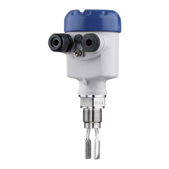
3 Product description Documents and software Further information can be found on our homepage. There you will find the documentation and further information about the device. Principle of operation Application area OPTISWITCH 5100 C, 5150 C is a point level sensor with tuning fork for point level detection. It is designed for industrial use in all areas of process technology and can be used in liquids. -
Page 8: Packaging, Transport And Storage
3 Product description On the electronics module you will find the following display and adjustment elements: • Control lamp for indication of the switching status • DIL switch for sensitivity adjustment • Mode switch to select the switching condition (reverse character- istics) • Simulation key Packaging, transport and storage Packaging Your instrument was protected by packaging during transport. -
Page 9: Plug Connector
3 Product description Plug connector For connecting the sensors with a separator to voltage supply or sig- nal processing, the sensors are also available with plug connectors. The following plug connectors are available: • M12 x 1 • ISO 4400 •... -
Page 10: Mounting
4 Mounting Mounting General instructions Note: Process conditions For safety reasons, the instrument must only be operated within the permissible process conditions. You can find detailed information on the process conditions in chapter " Technical data" of the operating instructions or on the type label. Hence make sure before mounting that all parts of the instrument ex- posed to the process are suitable for the existing process conditions. - Page 11 4 Mounting Fig. 2: Vertical mounting Switching point approx. 13 mm (0.51 in) Switching point with lower density Switching point with higher density Switching point approx. 27 mm (1.06 in) Fig. 3: Horizontal mounting Switching point Marking with screwed version, facing up Fig.
- Page 12 4 Mounting Fig. 5: Fork position with flange versions 1 Marking with flange version, facing up Protection against mois- Protect your instrument against moisture ingress through the following ture measures: • Use a suitable connection cable (see chapter " Connecting to power supply") • Tighten the cable gland or plug connector •...
-
Page 13: Mounting Instructions
4 Mounting Warning: The housing must not be used to screw the instrument in! Applying tightening force can damage internal parts of the housing. Use the hexagon above the thread for screwing in. Cable glands Metric threads In the case of instrument housings with metric thread, the cable glands are screwed in at the factory. - Page 14 4 Mounting buildup on the tuning fork. On the screwed version you will find a marking on the hexagon. With this you can check the position of the tuning fork when screwing it in. When the hexagon touches the seal, the thread can still be turned by approx. half a turn. This is sufficient to reach the recommended installation position. In the case of flange versions, the fork is aligned with the flange holes. When used in adhesive and viscous products, the tuning fork should protrude into the vessel to avoid buildup.
-
Page 15: Connecting To Power Supply
5 Connecting to power supply Connecting to power supply Preparing the connection Note safety instructions Always keep in mind the following safety instructions: Warning: Connect only in the complete absence of line voltage. • The electrical connection must only be carried out by trained, qualified personnel authorised by the plant operator. -
Page 16: Wiring Plan, Single Chamber Housing
5 Connecting to power supply 2. Loosen compression nut of the cable gland and remove blind plug 3. Remove approx. 10 cm (4 in) of the cable mantle, strip approx. 1 cm (0.4 in) of insulation from the ends of the individual wires 4. -
Page 17: Wiring Plan
5 Connecting to power supply Electronics and connec- tion compartment SW E60N Ex N A M U R ( I E C 6 0 9 4 7 - 5 - 6 ) 0,5 g / cm 3 M a x . S i m u l . -
Page 18: Setup
6 Setup Setup General information The figures in brackets refer to the following illustrations. Function/Configuration The switching condition of the electronics can be checked when the housing cover is closed (control lamp). With the basic setting, products with a density ≥ 0.7 g/cm³ (0.025 lbs/in³) can be detected. For products with lower density, the switch must be set to ≥ 0.5 g/cm³ (0.018 lbs/in³). On the electronics module you will find the following display and adjustment elements: • Signal lamp (1) • DIL switch for characteristics reversal - min./max. (2) •... -
Page 19: Function Table
6 Setup • red (flashing) = Failure ≤ 1.0 mA Characteristics reversal The characteristics reversal can be carried out with the DIL switch. You can choose between falling characteristic curve (switch position max.) and rising characteristic curve (switch position min.). This al- lows you to output the desired current. Modes •... - Page 20 6 Setup Level Switching status Control lamp Falling character- ≥ 2.2 mA istics max. Falling character- ≤ 1.0 mA istics max. Rising character- ≥ 2.2 mA istics min. Rising character- ≤ 1.0 mA istics min. Fault ≤ 1.0 mA flashes red OPTISWITCH 5100 C, 5150 C • NAMUR...
-
Page 21: Maintenance And Fault Rectification
7 Maintenance and fault rectification 7 Maintenance and fault rectification Maintenance Maintenance If the device is used properly, no special maintenance is required in normal operation. Cleaning The cleaning helps that the type label and markings on the instrument are visible. Take note of the following: • Use only cleaning agents which do not corrode the housings, type label and seals •... -
Page 22: Exchanging The Electronics
7 Maintenance and fault rectification Error Cause Rectification Signal lamp flashes red Error on the vibrating el- Check if the vibrating element is damaged or extreme- ement ly corroded. Interference on the elec- Exchanging the electronics module tronics module Instrument defective Exchange the instrument or send it in for repair Reaction after fault recti- Depending on the reason for the fault and the measures taken, the fication... -
Page 23: Dismount
8 Dismount Dismount Dismounting steps To remove the device, carry out the steps in chapters " Mounting" and " Connecting to power suplly" in reverse. Warning: When dismounting, pay attention to the process conditions in vessels or pipelines. There is a risk of injury, e.g. due to high pressures or tem- peratures as well as aggressive or toxic media. -
Page 24: Supplement
9 Supplement Supplement Technical data Note for approved instruments The technical data in the respective safety instructions which are included in delivery are valid for approved instruments (e.g. with Ex approval). These data can differ from the data listed herein, for example regarding the process conditions or the voltage supply. All approval documents can be downloaded from our homepage. General data Material 316L corresponds to 1.4404 or 1.4435 Materials, wetted parts... - Page 25 9 Supplement Ʋ Supporting material 316L Ʋ Glass potting Borosilicate glass (Schott no. 8421) Ʋ Contacts 1.4101 Ʋ Helium leak rate < 10 mbar l/s Ʋ Pressure resistance PN 64 Sensor length Ʋ Length OPTISWITCH 5100 C, 5150 C See chapter " Dimensions" Instrument weight (depending on pro- 0.8 …...
- Page 26 9 Supplement Necessary processing system NAMUR processing system according to IEC 60947-5-6 (EN 50227/DIN 19234) Modes (NAMUR output adjustable to falling or rising characteristics) Ʋ Min. rising characteristic curve (High current when immersed) Ʋ Max. falling characteristics (Low current when immersed) Measurement accuracy (according to DIN EN 60770-1) Reference conditions and influencing variables (according to DIN EN 61298-1) Ʋ...
- Page 27 9 Supplement Influence of the product density on the switching point ") ") ") ") ") ") ") ") ") ") (0,022) (0,029) (0,036) (0,043) (0,051) (0,058) (0,065) (0,072) (0,079) (0,087) Fig. 12: Influence of the product density on the switching point Shifting of the switching point in mm (in) Product density in g/cm³ (lb/in³) Switch position ≥ 0.5 g/cm³ (0.018 lb/in³) Switch position ≥ 0.7 g/cm³ (0.025 lb/in³) Switching point at reference conditions (notch) Tuning fork Influence of the process pressure to the switching point ")
- Page 28 9 Supplement Ʋ Can be ordered optionally approx. 250 ms (on/off) Measuring frequency approx. 1200 Hz Ambient conditions Ambient temperature on the housing -40 … +70 °C (-40 … +158 °F) Storage and transport temperature -40 … +80 °C (-40 … +176 °F) Process conditions Measured variable Limit level of liquids...
- Page 29 9 Supplement 70 °C (158 °F) 40 °C (104 °F) 0 °C (32 °F) -50 °C 50 °C 100 °C 150 °C 200 °C 250 °C (-58 °F) (122 °F) (212 °F) (302 °F) (392 °F) (482 °F) -40 °C (-40 °F) Fig.
- Page 30 9 Supplement Additional process conditions Viscosity - dynamic 0.1 … 10000 mPa s (requirement: with density 1) Flow velocity max. 6 m/s (with a viscosity of 10000 mPa s) Density Ʋ Standard sensitivity 0.7 … 2.5 g/cm³ (0.025 … 0.09 lbs/in³) Ʋ High sensitivity 0.5 … 2.5 g/cm³ (0.018 … 0.09 lbs/in³) Vibration resistance Ʋ Instrument housing 1 g at 5 … 200 Hz according to EN 60068-2-6 (vibration with resonance) Ʋ...
-
Page 31: Dimensions
9 Supplement Dimensions OPTISWITCH 5100 C, 5150 C, housing ~ 59 mm ~ 69 mm ~ 116 mm (4.57") ~ 116 mm (4.57") (2.32") (2.72") ø 80 mm ø 86 mm (3.39") ø 86 mm (3.39") ø 79 mm (3.15") (3.03") M20x1,5 M20x1,5/... - Page 32 9 Supplement OPTISWITCH 5100 C, 5150 C 32 (G¾A, ¾"NPT) 41 (G1A, 1"NPT) G¾A, ¾"NPT G1A, 1"NPT ø 33,7 mm (1.33") Fig. 18: OPTISWITCH 5100 C, 5150 C Thread Clamp Cone DN 25 Slotted nut DN 40 Flange Tuchenhagen Varivent OPTISWITCH 5100 C, 5150 C •...
- Page 33 9 Supplement OPTISWITCH 5100 C, 5150 C, options Fig. 19: Options Gas-tight leadthrough Temperature adapter OPTISWITCH 5100 C, 5150 C • NAMUR...
-
Page 34: Trademark
9 Supplement Trademark All the brands as well as trade and company names used are property of their lawful proprietor/ originator. OPTISWITCH 5100 C, 5150 C • NAMUR... - Page 35 Notes OPTISWITCH 5100 C, 5150 C • NAMUR...
- Page 36 • training services Head Office KROHNE Messtechnick GmbH Ludwig-Krohne-Straße 5 47058 Duisburg (Germany) Tel.: +49 (0) 203 301 0 Tel.: +49 (0) 203 301 10389 info@krohne.de The current list of all KROHNE contacts and addresses can be found at: www.krohne.com...
Need help?
Do you have a question about the OPTISWITCH 5150 C and is the answer not in the manual?
Questions and answers