Table of Contents
Advertisement
Quick Links
Advertisement
Table of Contents

Related Manuals for KROHNE OPTISWITCH 4000 C


Summary of Contents for KROHNE OPTISWITCH 4000 C
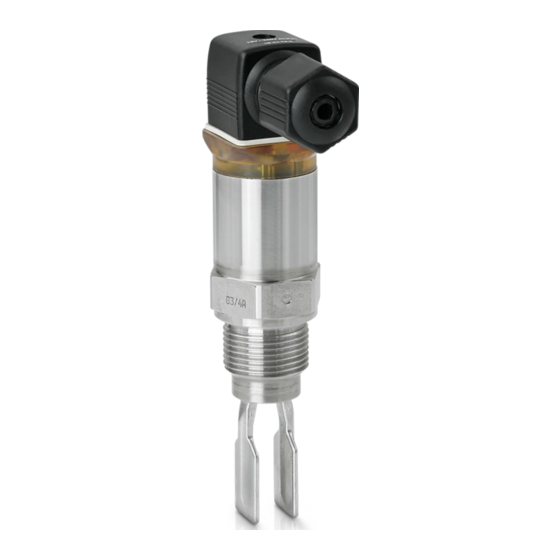
- Page 1 OPTISWITCH 4000 C Handbook Vibrating Level Switch Transistor (PNP)
-
Page 2: Table Of Contents
How to proceed if a repair is necessary ................21 Dismount..........................22 Dismounting steps......................22 Disposal ......................... 22 Supplement ..........................23 Technical data ........................ 23 Dimensions ........................27 Trademark ........................30 Editing status: 2019-11-21 OPTISWITCH 4000 C • Transistor (PNP) -
Page 3: About This Document
The dot set in front indicates a list with no implied sequence. Sequence of actions Numbers set in front indicate successive steps in a procedure. Battery disposal This symbol indicates special information about the disposal of bat- teries and accumulators. OPTISWITCH 4000 C • Transistor (PNP) -
Page 4: For Your Safety
During work on and with the device, the required personal protective equipment must always be worn. Appropriate use The OPTISWITCH 4000 C is a sensor for point level detection. You can find detailed information about the area of application in chapter "Product description". Operational reliability is ensured only if the instrument is properly used according to the specifications in the operating instructions manual as well as possible supplementary instructions. -
Page 5: Safety Label On The Instrument
This information is only valid for USA and Canada. Hence the follow- ing text is only available in the English language. Installations in the US shall comply with the relevant requirements of the National Electrical Code (ANSI/NFPA 70). Installations in Canada shall comply with the relevant requirements of the Canadian Electrical Code. OPTISWITCH 4000 C • Transistor (PNP) -
Page 6: Product Description
Article numbers, documentation Principle of operation Application area OPTISWITCH 4000 C is a point level sensor with tuning fork for point level detection. It is designed for industrial use in all areas of process technology and can be used in liquids. -
Page 7: Adjustment
Voltage supply OPTISWITCH 4000 C is a compact instrument, i.e. it can be oper- ated without external evaluation system. The integrated electronics evaluates the level signal and outputs a switching signal. With this switching signal, a connected device can be operated directly (e.g. a warning system, a pump etc.). -
Page 8: Packaging, Transport And Storage
Protected against solar radiation • Avoiding mechanical shock and vibration • Storage and transport Storage and transport temperature see chapter "Supplement - temperature Technical data - Ambient conditions" • Relative humidity 20 … 85 % OPTISWITCH 4000 C • Transistor (PNP) -
Page 9: Mounting
DIN/EN/IEC/ANSI/ISA/UL/CSA 61010-1. Switching point In general, OPTISWITCH 4000 C can be installed in any position. The instrument only has to be mounted in such a way that the tuning fork is at the height of the desired switching point. - Page 10 Use the recommended cables (see chapter "Connecting to power supply") and tighten the cable gland. You can give your OPTISWITCH 4000 C additional protection against moisture penetration by leading the connection cable downward in front of the cable gland. Rain and condensation water can thus drain off. This applies mainly to outdoor mounting as well as installation in...
-
Page 11: Mounting Instructions
Welded socket For threaded versions of OPTISWITCH 4000 C in combination with a mounting boss with O-ring in front and welding marking. OPTISWITCH 4000 C with thread sizes ¾" and 1" have a defined thread. This means that every OPTISWITCH 4000 C is in the same position after being screwed in. Remove therefore the supplied flat seal from the thread of OPTISWITCH 4000 C. This flat seal is not required when using a welded socket with front-flush seal. Before welding, unscrew OPTISWITCH 4000 C and remove the rub- ber ring from the welded socket. - Page 12 Fig. 6: Adhesive products Inflowing medium If OPTISWITCH 4000 C is mounted in the filling stream, unwanted false measurement signals can be generated. For this reason, mount OPTISWITCH 4000 C at a position in the vessel where no disturbanc- es, e.g. from filling openings, agitators, etc., can occur. Product flow To make sure the tuning fork of OPTISWITCH 4000 C generates as little resistance as possible to product flow, mount the sensor so that the surfaces are parallel to the product movement.
-
Page 13: Connecting To Power Supply
Make sure that the cable used has the required temperature resist- ance and fire safety for max. occurring ambient temperature When mounting outdoors, on cooled vessels or in moist areas in which cleaning is made with steam or high pressure, the sealing of the cable gland is very important. OPTISWITCH 4000 C • Transistor (PNP) -
Page 14: Wiring Plan
IP66/IP67 or IP68 (0.2 bar). Valve plug ISO 4400 For this plug version, standard cable with round wire cross-section can be used. Cable diameter 4.5 … 7 mm, protection IP65. OPTISWITCH 4000 C • Transistor (PNP) - Page 15 Cable diameter 5.5 … 8 mm, protection IP67. Fig. 9: Connection, valve plug ISO 4400 with IDC crimping technology Compression nut Cable Seal ring Terminal insert Plug housing OPTISWITCH 4000 C • Transistor (PNP)
- Page 16 5 Connecting to power supply Transistor output For connection to binary inputs of a PLC. Max. Min. Fig. 10: Wiring plan, Transistor output with valve plug ISO 4400 PA Potential equalisation Load resistance (contactor, relay, etc.) OPTISWITCH 4000 C • Transistor (PNP)
- Page 17 5 Connecting to power supply Min. Max. Fig. 11: Wiring plan (housing), transistor output with M12 x 1 plug connection Brown White Blue Black Load resistance (contactor, relay, etc.) OPTISWITCH 4000 C • Transistor (PNP)
-
Page 18: Setup
You can check the change on the signal lamp. Please note that all connected device are activated during the simulation. If OPTISWITCH 4000 C does not switch over after several tests with the test magnet, you have to check the plug connection and the connection cable and try it again. -
Page 19: Function Table
Control lamp Yellow - cov- Green - voltage Red - fault sig- erage indication Max. mode of op- closed eration Max. mode of op- open eration Min. mode of op- closed eration Min. mode of op- open eration Fault open OPTISWITCH 4000 C • Transistor (PNP) -
Page 20: Maintenance And Fault Rectification
Buildup on the vi- Check the vibrating element and brating element the sensor if there is buildup and re- move it Vibrating element Check if the vibrating element is dam- damaged age or extremely corroded OPTISWITCH 4000 C • Transistor (PNP) -
Page 21: How To Proceed If A Repair Is Necessary
"Set up" may have to be carried out again. How to proceed if a repair is necessary If it is necessary to repair the instrument, please contact the responsi- ble Krohne agency. OPTISWITCH 4000 C • Transistor (PNP) -
Page 22: Dismount
Pass the instrument directly on to a specialised recycling company and do not use the municipal collecting points. If you have no way to dispose of the old instrument properly, please contact us concerning return and disposal. OPTISWITCH 4000 C • Transistor (PNP) -
Page 23: Supplement
Ʋ Hygienic fitting F 40 PN 25 Max. torque - process fitting Ʋ Thread G½, ½ NPT 50 Nm (37 lbf ft) Ʋ Thread G¾, ¾ NPT 75 Nm (55 lbf ft) Ʋ Thread G1, 1 NPT 100 Nm (73 lbf ft) OPTISWITCH 4000 C • Transistor (PNP) - Page 24 (212 °F) Fig. 13: Dependendency ambient temperature to process temperature Ambient temperature in °C (°F) Process temperature in °C (°F) Process temperature - High temperature -40 … +150 °C (-40 … +302 °F) version (option) OPTISWITCH 4000 C • Transistor (PNP)
- Page 25 Switching voltage < 34 V DC Blocking current < 10 µA Mode Ʋ Min./Max. Changeover by electronic connection Ʋ Max. Overflow protection Ʋ Min. Dry run protection Voltage supply Operating voltage 9.6 … 35 V DC OPTISWITCH 4000 C • Transistor (PNP)
- Page 26 Overvoltage category The feeding power supply unit can be connected to networks of overvoltage category III. Protection class Approvals Depending on the version, instruments with approvals can have different technical data. For these instruments, please note the corresponding approval documents. They are included in the scope of delivery. OPTISWITCH 4000 C • Transistor (PNP)
-
Page 27: Dimensions
9 Supplement Dimensions OPTISWITCH 4000 C, standard version - thread 42 mm 36 mm (1.65") (1.42") 28 mm 27 mm (1.1") (1.06") M12 x 1 ø 31,7 mm (1.25") SW 32 mm (1.26") NPT, NPT, G 1, 1 NPT, ø 17 mm ø... - Page 28 9 Supplement OPTISWITCH 4000 C, high temperature version - thread G¾, G1, ¾ NPT, 1 NPT 42 mm 36 mm (1.65") (1.42") 28 mm 27 mm (1.1") (1.06") M12 x 1 ø 31,7 mm (1.25") SW 32 mm (1.26") NPT,...
- Page 29 DN40 PN40: 103 mm (4.06 in) DN50 PN25: 104 mm (4.09 in) L3 Length with SMS DN38 PN6: 94 mm (3.70 in) L4 Length with aseptic fitting 134 mm (5.28 in) Note that the overall length is increased by the plug connection. OPTISWITCH 4000 C • Transistor (PNP)
-
Page 30: Trademark
9 Supplement Trademark All the brands as well as trade and company names used are property of their lawful proprietor/ originator. OPTISWITCH 4000 C • Transistor (PNP) - Page 31 Notes OPTISWITCH 4000 C • Transistor (PNP)
- Page 32 Products and systems for the oil and gas industry KROHNE Messtechnick GmbH & Co. KG Ludwig-Krohne-Straße 5 D-47058 Duisburg Tel.: +49 (0) 203 301 0 Tel.: +49 (0) 203 301 10389 info@krohne.de The current list of all KROHNE contacts and addresses can be found at: www.krohne.com...
Need help?
Do you have a question about the OPTISWITCH 4000 C and is the answer not in the manual?
Questions and answers