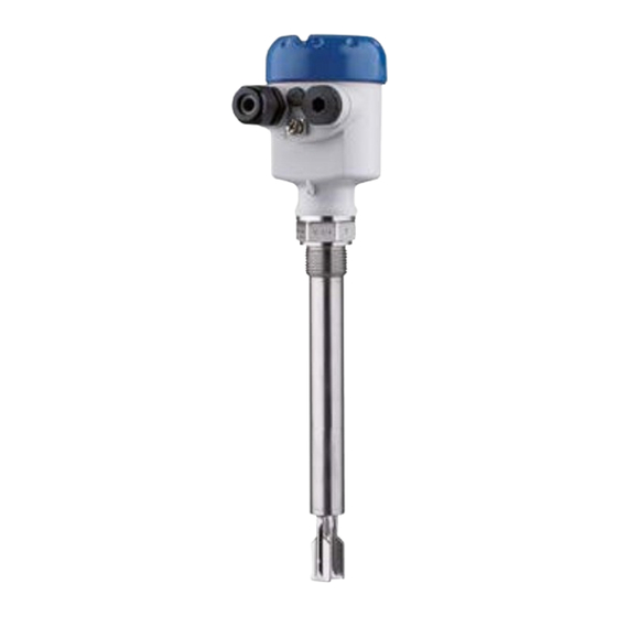
KROHNE OPTISWITCH 5250 C Handbook
Vibrating level switch/contactless electronic switch
Hide thumbs
Also See for OPTISWITCH 5250 C:
- Operating instructions book manual (45 pages) ,
- Handbook (44 pages) ,
- Operating instructions manual (36 pages)

Related Manuals for KROHNE OPTISWITCH 5250 C


Summary of Contents for KROHNE OPTISWITCH 5250 C
- Page 1 OPTISWITCH 5200 Handbook C, 5250 C Vibrating Level Switch Contactless electronic switch...
-
Page 2: Table Of Contents
Contents Contents About this document ....................... 3 Function ........................... 3 Target group ........................3 Symbols used........................3 For your safety ......................... 4 Authorised personnel ....................... 4 Appropriate use ........................ 4 Warning about incorrect use ..................... 4 General safety instructions ....................4 Conformity ........................ -
Page 3: About This Document
1 About this document About this document Function This instruction provides all the information you need for mounting, connection and setup as well as important instructions for mainte- nance, fault rectification, safety and the exchange of parts. Please read this information before putting the instrument into operation and keep this manual accessible in the immediate vicinity of the device. Target group This operating instructions manual is directed to trained personnel. -
Page 4: For Your Safety
2 For your safety For your safety Authorised personnel All operations described in this documentation must be carried out only by trained and authorized personnel. During work on and with the device, the required personal protective equipment must always be worn. Appropriate use The OPTISWITCH 5200 C, 5250 C is a sensor for point level detec- tion. -
Page 5: Sil Conformity
2 For your safety The corresponding conformity declarations can be found on our homepage. SIL conformity OPTISWITCH 5200 C, 5250 C fulfills the requirements to functional safety according to IEC 61508 or IEC 61511. You find further informa- tion in the supplied Safety Manual. Installation and operation in the USA and Canada This information is only valid for USA and Canada. Hence the follow- ing text is only available in the English language. -
Page 6: Product Description
3 Product description Product description 3.1 Configuration Scope of delivery The scope of delivery encompasses: • OPTISWITCH 5200 C, 5250 C point level switch The further scope of delivery encompasses: • Documentation – Operating instructions OPTISWITCH 5200 C, 5250 C –... -
Page 7: Principle Of Operation
3 Product description • Configuration information • Technical data • Serial number of the instrument • QR code for device identification • Manufacturer information Documents and software Further information can be found on our homepage. There you will find the documentation and further information about the device. Principle of operation Application area OPTISWITCH 5200 C, 5250 C is a point level sensor with tuning fork for point level detection. -
Page 8: Adjustment
3 Product description Adjustment The switching condition of OPTISWITCH 5200 C, 5250 C with plastic housing can be checked when the housing is closed (signal lamp). With the basic setting, products with a density ≥ 0.7 g/cm³ (0.025 lbs/ in³) can be detected. The instrument can be adapted if products with lower density are to be measured. On the electronics module you will find the following display and adjustment elements: • Signal lamp for indication of the switching condition (green/red) • DIL switch for sensitivity adjustment •... -
Page 9: Accessories
3 Product description Accessories Flanges Screwed flanges are available in different versions according to the following standards: DIN 2501, EN 1092-1, BS 10, ASME B 16.5, JIS B 2210-1984, GOST 12821-80. Plug connector For connecting the sensors with a separator to voltage supply or sig- nal processing, the sensors are also available with plug connectors. The following plug connectors are available: • M12 x 1 •... -
Page 10: Mounting
4 Mounting Mounting General instructions Note: Process conditions For safety reasons, the instrument must only be operated within the permissible process conditions. You can find detailed information on the process conditions in chapter " Technical data" of the operating instructions or on the type label. Hence make sure before mounting that all parts of the instrument ex- posed to the process are suitable for the existing process conditions. - Page 11 4 Mounting Fig. 2: Vertical mounting Switching point approx. 13 mm (0.51 in) Switching point with lower density Switching point with higher density Switching point approx. 27 mm (1.06 in) Fig. 3: Horizontal mounting Switching point Marking with screwed version, facing up Fig.
- Page 12 4 Mounting Fig. 5: Fork position with flange versions 1 Marking with flange version, facing up Protection against mois- Protect your instrument against moisture ingress through the following ture measures: • Use a suitable connection cable (see chapter " Connecting to power supply") • Tighten the cable gland or plug connector •...
-
Page 13: Mounting Instructions
4 Mounting Cable glands Metric threads In the case of instrument housings with metric thread, the cable glands are screwed in at the factory. They are sealed with plastic plugs as transport protection. You have to remove these plugs before electrical connection. NPT thread In the case of instrument housings with self-sealing NPT threads, it is not possible to have the cable entries screwed in at the factory. - Page 14 4 Mounting In the case of flange versions, the fork is aligned with the flange holes. When used in adhesive and viscous products, the tuning fork should protrude into the vessel to avoid buildup. For that reason, nozzles for flanges and mounting bosses should be avoided when mounting horizontally. Pressure/Vacuum The process fitting must be sealed if there is gauge or low pressure in the vessel. Before use, check if the sealing material is resistant against the measured product and the process temperature. The max. permissible pressure is specified in chapter " Technical data" or on the type label of the sensor. Inflowing medium If OPTISWITCH 5200 C, 5250 C is mounted in the filling stream, un- wanted false measurement signals can be generated.
- Page 15 4 Mounting Fig. 8: Lateral suppot of OPTISWITCH 5200 C, 5250 C Gas-tight leadthrough The second seal of the gas-tight leadthrough (option) prevents an uncontrolled leakage of the medium. The service life of the gas-tight leadthrough depends on the chemical resistance of the materials. See "...
-
Page 16: Connecting To Power Supply
5 Connecting to power supply Connecting to power supply Preparing the connection Note safety instructions Always keep in mind the following safety instructions: Warning: Connect only in the complete absence of line voltage. • The electrical connection must only be carried out by trained, qualified personnel authorised by the plant operator. -
Page 17: Connection Procedure
5 Connecting to power supply Connection procedure With Ex instruments, the housing cover may only be opened if there is no explosive atmosphere present. Proceed as follows: 1. Unscrew the housing lid 2. Loosen compression nut of the cable gland and remove blind plug 3. - Page 18 5 Connecting to power supply Electronics and connec- tion compartment SW E60C 2 0 - 2 5 0 V A C / D C m a x 4 0 0 m A 0,5 g / cm 3 0,7 g / cm 3 Fig.
- Page 19 5 Connecting to power supply When OPTISWITCH 5200 C, 5250 C is used as part of an overfill protection system according to WHG, also note the regulations of the general type approval. Fig. 11: Wiring plan, single chamber housing OPTISWITCH 5200 C, 5250 C • Contactless electronic switch...
-
Page 20: Setup
6 Setup Setup General information The figures in brackets refer to the following illustrations. Function/Configuration With plastic housings, the switching condition of the electronics can be checked when the housing cover is closed (control lamp). With the basic setting, products with a density ≥ 0.7 g/cm³ (0.025 lbs/in³) can be detected. For products with lower density, the switch must be set to ≥ 0.5 g/cm³ (0.018 lbs/in³). -
Page 21: Function Table
6 Setup " Function table" (A - max. detection or overflow protection, B - min. detection or dry run protection). Adjustment of the density With this DIL switch (3) you can set the switching point to liquids range (3) having a density between 0.5 and 0.7 g/cm³ (0.018 and 0.025 lbs/ in³). With the basic setting, liquids with a density of ≥ 0.7 g/cm³ (0.025 lbs/in³) can be detected. In liquids with lower density, you must set the switch to ≥ 0.5 g/cm³ (0.018 lbs/in³). The specifications for the position of the switching point relate to water - density value 1 g/cm³ (0.036 lbs/in³). In products with a different density, the switching point will shift in the direction of the housing or tuning fork end depending on the density and type of installation. - Page 22 6 Setup Level Switching status Control lamp Fault Switch open flashes red OPTISWITCH 5200 C, 5250 C • Contactless electronic switch...
-
Page 23: Maintenance And Fault Rectification
7 Maintenance and fault rectification 7 Maintenance and fault rectification Maintenance Maintenance If the device is used properly, no special maintenance is required in normal operation. Cleaning The cleaning helps that the type label and markings on the instrument are visible. Take note of the following: • Use only cleaning agents which do not corrode the housings, type label and seals •... -
Page 24: Exchanging The Electronics
7 Maintenance and fault rectification Checking the switching signal Error Cause Rectification OPTISWITCH 5200 C, 5250 C Operating voltage too low Check operating voltage signals "covered" without being sub- Electronics defective Press the mode switch. If the instru- merged (overfill protection) ment then changes the mode, the OPTISWITCH 5200 C, 5250 C vibrating element may be covered signals "uncovered"... -
Page 25: How To Proceed If A Repair Is Necessary
7 Maintenance and fault rectification How to proceed if a repair is necessary If a repair should be necessary, please contact your contact person. OPTISWITCH 5200 C, 5250 C • Contactless electronic switch... -
Page 26: Dismount
8 Dismount Dismount Dismounting steps To remove the device, carry out the steps in chapters " Mounting" and " Connecting to power suplly" in reverse. Warning: When dismounting, pay attention to the process conditions in vessels or pipelines. There is a risk of injury, e.g. due to high pressures or tem- peratures as well as aggressive or toxic media. -
Page 27: Supplement
9 Supplement Supplement Technical data Note for approved instruments The technical data in the respective safety instructions which are included in delivery are valid for approved instruments (e.g. with Ex approval). These data can differ from the data listed herein, for example regarding the process conditions or the voltage supply. All approval documents can be downloaded from our homepage. General data Material 316L corresponds to 1.4404 or 1.4435 Materials, wetted parts... - Page 28 9 Supplement Ʋ Supporting material 316L Ʋ Glass potting Borosilicate glass (Schott no. 8421) Ʋ Contacts 1.4101 Ʋ Helium leak rate < 10 mbar l/s Ʋ Pressure resistance PN 64 Sensor length (L) Ʋ 316L, Alloy C22 (2.4602) 80 … 6000 mm (3.15 … 236.22 in) Ʋ...
- Page 29 9 Supplement Modes (switchable) Ʋ A Max. detection or overflow/overfill protection Ʋ B Min. detection or dry run protection Measurement accuracy (according to DIN EN 60770-1) Reference conditions and influencing variables (according to DIN EN 61298-1) Ʋ Ambient temperature +18 … +30 °C (+64 … +86 °F) Ʋ Relative humidity 45 … 75 % Ʋ...
- Page 30 9 Supplement Influence of the product density on the switching point ") ") ") ") ") ") ") ") ") ") (0,022) (0,029) (0,036) (0,043) (0,051) (0,058) (0,065) (0,072) (0,079) (0,087) Fig. 14: Influence of the product density on the switching point Shifting of the switching point in mm (in) Product density in g/cm³ (lb/in³) Switch position ≥ 0.5 g/cm³ (0.018 lb/in³) Switch position ≥ 0.7 g/cm³ (0.025 lb/in³) Switching point at reference conditions (notch) Tuning fork Influence of the process pressure to the switching point ")
- Page 31 9 Supplement Ambient conditions Ambient temperature on the housing -40 … +70 °C (-40 … +158 °F) Storage and transport temperature -40 … +80 °C (-40 … +176 °F) Process conditions Measured variable Limit level of liquids Process pressure -1 … 64 bar/-100 … 6400 kPa (-14.5 … 928 psig) The process pressure is dependent on the process fitting, for example Clamp or flange (see the following diagrams)
- Page 32 9 Supplement (928) (580) (290) -1 (-14,5) 0 °C -50 °C 50 °C 100 °C 150 °C 200 °C 250 °C (32 °F) (-58 °F) (122 °F) (212 °F) (302 °F) (392 °F) (482 °F) Fig. 17: Process temperature - Process pressure with switch position ≥ 0.7 g/cm³ (sensitivity switch) Process pressure in bar (psig) Process temperature in °C (°F) (928) (580)
- Page 33 9 Supplement Ʋ Sensor 1 g with 5 … 200 Hz according EN 60068-2-6 (vibration at resonance) with sensor length up to 50 cm (19.69 in) With a sensor length > 50 cm (19.69 in) you have to fix the extension tube with a suitable support. See mounting instructions. Electromechanical data Options of the cable entry Ʋ...
-
Page 34: Dimensions
9 Supplement Dimensions OPTISWITCH 5200 C, 5250 C, housing ~ 59 mm ~ 69 mm ~ 116 mm (4.57") ~ 116 mm (4.57") (2.32") (2.72") ø 80 mm ø 86 mm (3.39") ø 86 mm (3.39") ø 79 mm (3.15") (3.03") M20x1,5 M20x1,5/... - Page 35 9 Supplement OPTISWITCH 5200 C, 5250 C 32 (G "NPT) 41 (G1A, 1"NPT) "NPT G1A, 1"NPT ø 21,3 mm (0.84") ø 33,7 mm (1.33") Fig. 20: OPTISWITCH 5200 C, 5250 C Thread Clamp Cone DN 25 Slotted nut DN 40 Flange Tuchenhagen Varivent Sensor length, see chapter "...
- Page 36 9 Supplement OPTISWITCH 5200 C, 5250 C, options Fig. 21: Options Gas-tight leadthrough Temperature adapter OPTISWITCH 5200 C, 5250 C • Contactless electronic switch...
-
Page 37: Trademark
9 Supplement Trademark All the brands as well as trade and company names used are property of their lawful proprietor/ originator. OPTISWITCH 5200 C, 5250 C • Contactless electronic switch... - Page 38 Notes OPTISWITCH 5200 C, 5250 C • Contactless electronic switch...
- Page 39 Notes OPTISWITCH 5200 C, 5250 C • Contactless electronic switch...
- Page 40 • training services Head Office KROHNE Messtechnick GmbH Ludwig-Krohne-Straße 5 47058 Duisburg (Germany) Tel.: +49 (0) 203 301 0 Tel.: +49 (0) 203 301 10389 info@krohne.de The current list of all KROHNE contacts and addresses can be found at: www.krohne.com...
Need help?
Do you have a question about the OPTISWITCH 5250 C and is the answer not in the manual?
Questions and answers