Table of Contents
Advertisement
Advertisement
Chapters
Table of Contents

Related Manuals for Zeiss VISUREF 100


Summary of Contents for Zeiss VISUREF 100
- Page 1 VISUREF 100 Autorefractor/Keratometer Documentation set...
- Page 2 The weblinks are dynamic hyperlinks. Before incorporating any links, Carl Zeiss Meditec AG checks their content to ensure that it is not likely to result in civil or criminal liability. It does not, however, continuously check for any changes which could form the basis for liability.
- Page 3 Contents User Manual Autorefractor/Keratometer VISUREF 100 [000000-2006-367-GA-GB-151116] Appendix ZEISS VISUREF 100 - QuickGuide [000000-2006-367-QuG-DE-020615] 000000-2006-367-Inhalt0-GB-151116...
- Page 5 VISUREF 100 Autorefractor/Keratometer User Manual...
- Page 6 000000-2006-367-GA-GB-151116...
-
Page 7: Table Of Contents
Contents Contents Contents ..................1 Notes on the user manual ............4 Purpose and availability of documentation ............ 4 Questions and comments ................4 Explanation of symbols used ................5 Package check list ..............6 Country-specific information and labels ........7 Classification/Manufacturer's declaration ............ - Page 8 Contents Measuring a patient's eye ................29 Selecting measurement mode ..................29 Regulating the patient's eye level ................29 Focusing........................29 Manual measurement (MANU) .................30 Automatic measurement (AUTO) ................30 Continuous measurement ..................30 Measuring the other eye ...................30 Printing ........................30 Measurement modes ..................31 Refractometry (REF) ....................32 Keratometry (KER) .....................33 RK measurement mode ....................34...
- Page 9 Contents Abbreviations/Glossary ............. 69 Figures ..................70 Index ..................71 000000-2006-367-GA-GB-151116...
-
Page 10: Notes On The User Manual
Correct operation of the system is imperative for its safe and successful function. You should therefore ensure that you are thoroughly familiar with this user manual before setting up and using the VISUREF 100 for the first time. The user manuals and other documentation enclosed with the VISUREF 100 should be kept accessible to users at all times to ensure that the information required for use of the VISUREF 100 is readily available. -
Page 11: Explanation Of Symbols Used
Notes on the user manual Explanation of symbols used The symbols used in this user manual refer to important safety information which may warn against possible health risks or fatal injuries and contain useful notes. Whenever you see these symbols, read the accompanying information carefully and observe all safety notes and information in this user manual and on device labels. -
Page 12: Package Check List
Package check list Package check list The VISUREF 100 basic device is supplied with the parts shown in the following figure. 1 Power supply cable 2 Test eye 3 Printer paper (1 roll installed when delivered) 4 Documentation set 5 Dust cover 6 2 fuses (see section Technical data, page 62) Fig. -
Page 13: Country-Specific Information And Labels
Country-specific information and labels Country-specific information and labels Classification/Manufacturer's declaration WARNING - GENERAL HAZARDS This device may only be set up, operated and used for the specified purpose and according to national regulations, consistent with the applicable industry standards and occupational safety and accident prevention regulations. -
Page 14: Intended Use
Country-specific information and labels Intended Use An autorefractor/keratometer is used to determine the refractive and keratometric properties of the human eye. The measured values are used to assist opticians and eye care professionals in the process of prescribing eyeglasses and contact lenses. Intended user profile CAUTION - RISK OF OPERATING ERRORS This device may only be installed, operated, used and maintained by... -
Page 15: Disposal Of The Product
Country-specific information and labels Disposal of the product CAUTION - RISK OF ENVIRONMENTAL POLLUTION Packaging materials should be retained for future relocation or repair. If you decide to dispose of the packaging material, submit it to a recognized collection system for recycling. The device contains electronic components. -
Page 16: External Labels
Country-specific information and labels External labels Fig. 2 Labels on the VISUREF 100 000000-2006-367-GA-GB-151116... - Page 17 Country-specific information and labels Item Label Explanation VISUREF 100 type plate Manufacturer Date of manufacture Application part type B VISUREF 100 identification label Catalogue number/part number Serial number Sign with date of manufacture CE approval label and disposal advise for...
- Page 18 Country-specific information and labels Item Label Explanation Approval label for Brazil Not applicable Not applicable Not applicable Not applicable 000000-2006-367-GA-GB-151116...
-
Page 19: Performance Specifications
Dioptric range The VISUREF 100 covers a wide measurement range from -25 D to +22 D so that even a patient with strong refractive errors can be measured. User interface The convenient user interface provides a large 6.4"... -
Page 20: Description Of The Instrument
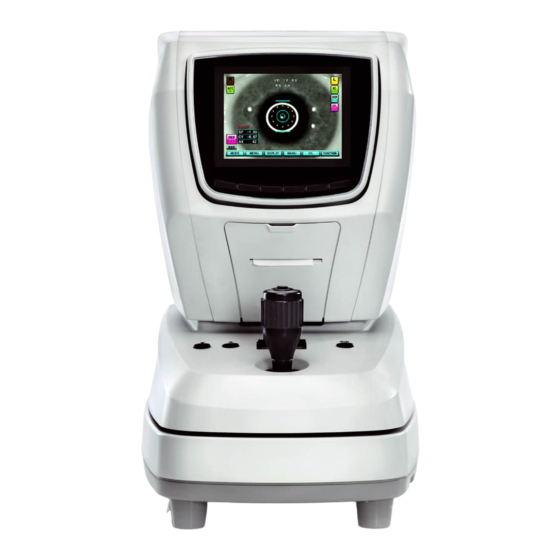
6 Buttons for chin rest height adjustment 7 Printer cover 8 Function keys F1 to F6 (from left to right) 9 Status LED (continuously lit - device switched on, flashing - screen saver activated) Fig. 3 VISUREF 100 - View from user side 000000-2006-367-GA-GB-151116... -
Page 21: Fig. 4 Visuref 100 - View From Patient Side
Description of the instrument 1 Forehead rest 2 Reference mark for optimum eye level of patient 3 Chin rest 4 Dust cap 5 Measurement window Fig. 4 VISUREF 100 - View from patient side 000000-2006-367-GA-GB-151116... -
Page 22: Fig. 5 Visuref 100 - Bottom Side
1 USB port (for service only) 2 RS232 port 3 Connection for external video equipment 4 Power switch 5 Power input socket 6 Fuses 7 Stage clamping screw to lock the stage during transportation Fig. 5 VISUREF 100 - Bottom side 000000-2006-367-GA-GB-151116... -
Page 23: User Interface
Description of the instrument User interface 1 Left eye symbol (not selected) 2 Patient ID 3 Increment 4 Cylinder units 5 Number of saved measurements in KER measurement mode for the selected eye 6 Assignment of function keys F1 to F6 (from left to right) 7 Selected measurement mode 8 Number of saved measurements in REF measurement mode for the selected eye 9 IOL icon (will only be shown if IOL function key has been pressed) -
Page 24: Function Key Assignment
Description of the instrument Function key assignment The assignment of the functions for the function keys depends on the selected measurement mode (see section Measurement modes, page 31). Assignment of function keys in main measurement modes After starting the user interface or after each change of measurement modes, the functions in the main measurement modes (REF, KER, RK, CLBC) are assigned as follows: Function key... -
Page 25: Assignment Of Function Keys In Size Measurement Mode
Description of the instrument Assignment of function keys in SIZE measurement mode When switching to the SIZE measurement mode, the functions are assigned as follows: Function key Symbol Functional description Not assigned MENU Open the User setting menu CLEAR Delete the measurement values for corneal size DATA Select the first or second measurement of the currently measured eye. -
Page 26: Installation
Installation Installation Notes on installation and use WARNING - GENERAL HAZARDS Do not store or operate the device in ambient conditions other than those specified (see section Technical data on page 62 and following). The device should be set up so that the power cable can be disconnected from the power supply quickly and easily without any tools. -
Page 27: Unpacking And Installing The Device
Installation WARNING - FIRE HAZARD The device is not suitable for operation in explosion risk areas (e.g. combustible mixture of anesthetic, cleaning or disinfecting agents with air, oxygen or nitrous oxide). Do not store alcohol and other flammable vapors and liquids in the vicinity of this equipment. -
Page 28: Fig. 7 Releasing The Stage Locking
Installation • Release the stage locking by turning the stage clamping bolt (7, Fig. 5) on the bottom of the device counterclockwise (A, Fig. 7). Now press the lever to the front (B, Fig. 7) to unlock the stage (3, Fig. 3). Fig. -
Page 29: Daily Use
Daily use Daily use WARNING - GENERAL HAZARDS Prior to using the device, the user must ensure that it is in a good condition and fully functioning. Furthermore, the user must follow the instructions in the user manual. The following inspections must be carried out each working day prior to use: •... -
Page 30: Operation Of The Device
Operation of the device Operation of the device CAUTION - GENERAL HAZARDS The patient should not touch the instrument with his/her hands. In particular, the instrument should not be used as a support or an aid for standing up. Do not operate the device with wet hands. CAUTION - RISK OF PINCHING Take precautions to ensure fingers and hands are not trapped when lifting the device. -
Page 31: Measurements With The Test Eye
Operation of the device Measurements with the test eye Practice measurement by using the test eye before measuring patient’s eyes. Fig. 8 Test eye • Place the test eye in the center of the chin rest. • Make sure the stage is moving freely. •... -
Page 32: Manual Measurement
• Automatic measurement begins when the eye is well focused. Due to the tolerances of the test eye and the normal tolerances for objective refraction, the reading on the VISUREF 100 may differ from the value printed for the test eye. 000000-2006-367-GA-GB-151116... -
Page 33: Printing
Operation of the device Printing Press the print button to start printing (2, Fig. 3). If the print preview is switched on (see section Measurement settings, page 45), the measurement results will be displayed first. Press the print button again to start printing (2, Fig. 3). CAUTION - PROPERTY DAMAGE If auto cutting mode is switched on, do not pull the paper before it cuts. -
Page 34: Fig. 10 Example Of A Printout
Operation of the device 1 AVE: Average value of measured values 2 #: Unreliable result, repeat measurement 3 [I]: Measurement with activated IOL function Fig. 10 Example of a printout Measurement results marked with "OUT" are outside the measuring range. 000000-2006-367-GA-GB-151116... -
Page 35: Measuring A Patient's Eye
Operation of the device Measuring a patient's eye CAUTION - RISK OF INJURY Pull the refractometer away from the patient when moving right or left to avoid injuring the face. CAUTION - RISK OF PINCHING Do not place hand or fingers under the chin rest. This could result in damage or injury. -
Page 36: Manual Measurement (Manu)
Operation of the device Manual measurement (MANU) • Press the measurement button (5, Fig. 3). The measurement result will be displayed on the screen. The measurement result will be displayed according to the settings of the functions VD, CYL and KERATO (see section Measurement settings, page 45). -
Page 37: Measurement Modes
Operation of the device Measurement modes VISUREF 100 provides the following main measurement modes: • Refractometry (REF) • Keratometry (KER) • Keratometry and Refractometry (RK) • Measuring the contact lens base curve (CLBC) By pressing the MODE function button you can switch between the main measurement modes. -
Page 38: Refractometry (Ref)
Operation of the device Refractometry (REF) A refractometry can be performed in the REF measurement mode. Prepare the measurement as described in the section Measuring a patient's eye, page 28 ff. The assignment of functions to function keys is described on page 18. -
Page 39: Keratometry (Ker)
Operation of the device Keratometry (KER) A keratometry can be performed in the KER measurement mode. Prepare the measurement as described in section Measuring a patient's eye, page 28 ff. The assignment of functions to function keys is described on page 18. -
Page 40: Rk Measurement Mode
Operation of the device RK measurement mode A combined refractometry and keratometry can be performed in the RK measurement mode. Prepare the measurement as described in section Measuring a patient's eye, page 28 ff. The assignment of functions to function keys is described on page 18. -
Page 41: Clbc Measurement Mode
Operation of the device CLBC measurement mode The base curve of contact lenses can be measured in CLBC measurement mode. PD 64 수 1 Measurement result 2 Display of CLBC measurement mode Fig. 14 CLBC measurement mode screen 1 Contact lens Fig. -
Page 42: Fig. 16 Test Eye
Operation of the device Fig. 16 Test eye • Place the test eye in the center of the chin rest (Fig. 16). • Perform the measurement as described in section Measurements with the test eye, page 25 ff. The assignment of functions to function keys is described on page 18. -
Page 43: Size Measurement Of Pupil And Cornea (Size)
Operation of the device Size measurement of pupil and cornea (SIZE) The diameters of the cornea and pupil can be measured in SIZE measurement mode. • Prepare the measurement as described in section Measuring a patient's eye, page 28 ff. The assignment of functions to function keys is described on page 19. -
Page 44: Fig. 18 Size Measurement Mode Screen After Pressing The
Operation of the device 1 Yellow measurement line 2 Diameter of pupil or cornea (in mm) 3 Set zoom 4 Blue measurement line Fig. 18 SIZE measurement mode screen after pressing the measurement button • Press the ZOOM function key to enlarge the image (2x or 3x). •... -
Page 45: Examination Of The Cornea (Illum)
Operation of the device Examination of the cornea (ILLUM) The ILLUM measurement mode enables checking for cataracts or scratches on the lens/cornea. • Prepare the measurement as described in section Measuring a patient's eye, page 28 ff. The assignment of functions to function keys is described on page 19. -
Page 46: Fig. 20 Illum Measurement Mode Screen After Pressing The
Operation of the device 1 Set zoom Fig. 20 ILLUM measurement mode screen after pressing the measurement button • Press the ZOOM function key to enlarge the image (2x). An enlarged part of the image will be displayed. • After pressing the ZOOM key, the assignment of the function keys will be changed as follows: ZOOM RETURN... -
Page 47: Fig. 21 Msr Measurement Mode Screen
Operation of the device Refractometry in ILLUM measurement mode (MSR function key) You can perform a refractometry in the ILLUM measurement mode using the MSR function key. After pressing the MSR function key, the MSR icon and the kerato ring are displayed on the screen. 1 MSR mode Fig. -
Page 48: Fig. 23 Image List
Operation of the device Image list (IMAGELIST function key) In ILLUM measurement mode press the IMAGELIST function key to switch to the list of saved images Fig. 23 Image list • Press the arrow buttons to select a specific image. The image information appears for the selected image. - Page 49 Operation of the device • The selected value will be highlighted. Press the arrow keys to change the value. • Press RESET button to reset all values to the default values. • Press EXIT function key to exit the parameter setting menu. 000000-2006-367-GA-GB-151116...
-
Page 50: Display Measured Data
Operation of the device Display measured data You can switch from all main measurement modes to the display mode by pressing DISPLAY button. A list of the measured values is displayed. Fig. 24 Display of measurement data • Select the REF, KER or CLBC function keys to display refractometry, keratometry or contact lens base curve data. -
Page 51: User Settings
Operation of the device User settings You can switch from all main measurement modes to the user settings by pressing MENU button. • Browse through the four pages of the user settings by pressing the PAGE function key. • Select the parameters (lines) to be changed by pressing the up and down arrow keys. - Page 52 Operation of the device -/+/+- Set the cylinder notation 0.0/10.0/12.0/ Enter corneal vertex distance (in mm) 13.5/15 DATA PREVIEW Switch off print preview Switch on print preview SPH SHIFT -2.0/…/+2.0 Compensate spherical diopters (in D) (step size 0.125 D) SHOOTING MODE NORMAL Pressing the measurement button releases a measurement FAST-3...
-
Page 53: Printer Setup (Print)
Operation of the device Printer setup (PRINT) Fig. 26 Print settings PRINT TYPE Print all data. Print average values and additionally a small image illustrating the refractive error of the measured eye. Print only average values. Printing is not activated. AUTO CUTTING After each printout the paper will be cut off automatically. -
Page 54: Fig. 27 Add A User-Defined Text To The Printout
Operation of the device Adding a user-defined text (USER MESSAGE) to the printout Fig. 27 Add a user-defined text to the printout • Move to the desired character by using the arrow keys. • Select the desired character by pressing the SELECT function key. •... -
Page 55: System Setup (System)
Operation of the device System setup (SYSTEM) Fig. 28 System settings KEY SOUND Switch off the sound for pressing a key. MIDDLE Set the sound for pressing a key to medium volume. Switch on the sound for pressing a key. LCD Bright 1/2/3/4/5 Set brightness of display from low (1) to high (5). -
Page 56: Other Settings (Etc.)
COM FORMAT ZEISS Transmission format when communicating with external equipment via the serial port. OUTPUT VIDEO Turn off display output to external video. Turn on display output to external video. CODE Service mode will be switched on. For ZEISS Service. 000000-2006-367-GA-GB-151116... -
Page 57: Shutting Down
Label the instrument clearly as being out of service and report the problem to the ZEISS Service. CAUTION - RISK OF ELECTRIC SHOCK Be sure to unplug if the system is not used for a longer period of time. -
Page 58: Maintenance And Care
The system may only be opened, put into operation, modified and repaired by the manufacturer’s customer service technicians or specialists expressly authorized in writing by Carl Zeiss Meditec. If in doubt, insist on seeing the written authorization or contact Carl Zeiss Meditec directly. -
Page 59: Error Messages When Printing
Possible cause Remedy The printer is out of NO PAPER Replace printer paper. paper. Turn the instrument off and on. If Fog motor 'FOG MOTOR FAIL' message is FOG MOTOR FAIL movement is displayed, please contact the ZEISS unstable. Service. 000000-2006-367-GA-GB-151116... -
Page 60: Replacing The Fuses
Maintenance and care Replacing the fuses WARNING - RISK OF ELECTRIC SHOCK The device must be switched off and disconnected from the power supply before being cleaned or serviced. WARNING - RISK OF ELECTRIC SHOCK Internal fuses may only be changed by service staff specially trained in maintenance and service work. -
Page 61: Inserting Printer Paper
Maintenance and care Inserting printer paper If a red line appears on the paper, or if NO PAPER is displayed on the bottom of the screen, please replace printer paper. 1 Printer paper insert slit Fig. 31 Inserting printer paper •... -
Page 62: Maintenance
Maintenance and care Maintenance Care and cleaning WARNING - RISK OF ELECTRIC SHOCK Prevent moisture from penetrating the instrument or keyboard. Disconnect the power cable from the power supply before cleaning or disinfecting the device. CAUTION - SURFACE DAMAGE TO THE DEVICE Use a disinfectant based on aldehyde and/or alcohol. - Page 63 Maintenance and care The outer surfaces of optical componentes (objective) can be cleaned if necessary. • Remove dust from optical surfaces by using a blower or a clean and grease-free brush. • Fine cleaning can be done with moist antistatic cleaning tissues. Please follow the instructions on the cleaning cloth packaging.
-
Page 64: Safety Inspections
Maintenance and care Safety inspections WARNING - RISK OF ELECTRIC SHOCK If no legal requirements exist in your country, the device must receive an electrical safety test in accordance with IEC 62353:2007. This test must be performed and documented by specialists disposing of the according know- how. -
Page 65: Optional Accessories
Optional accessories Optional accessories WARNING - GENERAL HAZARDS Use only accessories and spare parts approved by Carl Zeiss Meditec. A complete up-to-date list of accessories can be obtained from your dealer. 000000-2006-367-GA-GB-151116... -
Page 66: Transport
CAUTION - RISK OF INJURY Holding the box by the packing tape or rope may cause injury to your fingers. CAUTION - RISK OF INJURY Should the packaging material become damaged or wet, please contact ZEISS Service or your local distributor. 000000-2006-367-GA-GB-151116... - Page 67 Transport CAUTION - RISK OF INJURY Take care when cutting the packing tape, as it may snap up and cause injury. Hold the tape on both sides when cutting. Wear protective gloves when unpacking the device. Unpack the device on a level surface to prevent slipping. CAUTION - PROPERTY DAMAGE Do not place heavy objects (over 20 kg) on the package.
-
Page 68: Technical Data
Technical data Technical data Dimensions (W x D x H) 275 mm x 525 mm x 450 mm Weight 18 kg Power supply 100 V to 240 V AC ± 10 %, 50/60 Hz Power consumption 90 VA Fuses T2AH 250 V Protection class Ingress protection rating IP X0... - Page 69 Technical data Measurement precision in accordance with ISO 10342 Refraction, sphere better than ±0.25 D Refraction, cylinder better than ±0.25 D Refraction, cylinder axis better than ±5° Measurement precision in accordance with ISO 10343 Keratometry, corneal radius better than ±0.05 mm Keratometry, axis for radial difference in main sections ≤...
-
Page 70: Electromagnetic Compatibility
CAUTION - HAZARD DUE TO ELECTROMAGNETIC RADIATION The VISUREF 100 may not be placed next to or stacked together with other equipment, except in the device configurations described in this user manual. - Page 71 Guidance and manufacturer’s declaration - electromagnetic emissions The VISUREF 100 is intended for use in an electromagnetic environment as specified below. The customer or the user of the VISUREF 100 should ensure that it is used only in such an environment.
- Page 72 Guidance and manufacturer’s declaration - electromagnetic immunity The VISUREF 100 is intended for use in an electromagnetic environment as specified below. The customer or the user of the VISUREF 100 should ensure that it is used only in such an environment.
- Page 73 RF transmitters, an electromagnetic site survey should be considered. If the measured field strength in the location in which the VISUREF 100 is used exceeds the applicable RF compliance level above, the VISUREF 100 should be observed to verify normal operation. If abnormal performance is observed, additional measures may be necessary, such as re-orienting or relocating the VISUREF 100.
- Page 74 Recommended separation distances between portable and mobile RF communications equipment and the VISUREF 100 The VISUREF 100 is intended for use in an electromagnetic environment in which radiated RF disturbances are controlled. The customer or the user of the VISUREF 100 can help prevent electromagnetic interference by...
- Page 75 Abbreviations/Glossary Abbreviations/Glossary Axis CLBC Contact Lens Base Curvature Cylinder Diopter DDAC Quaternary ammonium compound for disinfection and cleaning Fig. Figure ILLUM Illumination Intraocular lens Keratometry (measurement mode) Measure Pupil distance Refractometry (measurement mode) Keratometry and Refractometry combination mode (RK) Sphere Target Vertex distance 000000-2006-367-GA-GB-151116...
- Page 76 Package check list ................. 6 Fig. 2 Labels on the VISUREF 100 ............10 Fig. 3 VISUREF 100 - View from user side ..........14 Fig. 4 VISUREF 100 - View from patient side ......... 15 Fig. 5 VISUREF 100 - Bottom side ............16 Fig.
- Page 77 Index Index Abbreviations .................... 69 Accessories, optional ................. 59 Add a user-defined text ................48 Care ......................56 CLBC ......................35 Cleaning ....................56 Combination mode of Keratometry and Refractometry ......34 Contact lens base curve ................35 Control of electrical safety ................. 58 Cornea ......................
- Page 78 Index KER ......................33 Keratometry....................33 Labels on the device ................. 10 Maintenance ..................... 56 Maintenance and care ................52 Manufacturer’s declaration ................. 7 Measured data..................44 Measurement Automatic ..................26, 30 Manual ....................26, 30 Measurement modes ................31 Measurement settings ................45 Measuring a patient's eye .................
- Page 79 Index Technical data ................... 62 Test eye ..................... 25 Transport....................60 Unpacking ....................21 User interface .................... 17 User settings....................45 000000-2006-367-GA-GB-151116...
- Page 80 Carl Zeiss Meditec AG Goeschwitzer Str. 51-52 07745 Jena Germany Phone: +49 3641 220 333 Fax: +49 3641 220 112 000000-2006-367-GA-GB-151116 Email: info.meditec@zeiss.com VISUREF 100 Internet: www.zeiss.com/med Specifications subject to change...
- Page 82 Carl Zeiss Meditec AG Goeschwitzer Str. 51-52 07745 Jena Germany Phone: +49 3641 220 333 Fax: +49 3641 220 112 Email: info.meditec@zeiss.com Internet: www.zeiss.com/med VISUREF 100 Specifications subject to change 000000-2006-367-DokS-GB-151116...
Need help?
Do you have a question about the VISUREF 100 and is the answer not in the manual?
Questions and answers