Table of Contents
Advertisement
Advertisement
Table of Contents

Related Manuals for Zeiss Humphrey FDT 710


Summary of Contents for Zeiss Humphrey FDT 710
- Page 1 Humphrey FDT Model 710 User Manual...
- Page 2 ©2013 Carl Zeiss Meditec, Inc. All rights reserved. Trademarks Humphrey and FDT are either registered trademarks or trademarks of Carl Zeiss Meditec, Inc. in the United States and/or other countries. All other trademarks used in this document are the property of their respective owners.
-
Page 3: Table Of Contents
Contents (1) Safety Information ................ 1-1 Product Safety ....................1-1 Symbols and Labels....................1-3 Protective Packing Symbols................1-4 Product Labels and Serial Number Location ..........1-4 External Device Equipment.................1-4 Standards ......................1-5 Product Compliance ..................1-5 Electromagnetic Compatibility (EMC) ..............1-5 Guidance and Manufacturer’s Declarations ............1-6 (2) Introduction..................2-1 Intended Use .....................2-1 Indications for Use.....................2-1 Essential Performance ................2-1... - Page 4 (4) Calibration and Set-up ..............4-1 Calibration and Set-up ..................4-1 Set Date and Time..................4-1 Set-up Instrument Options.................4-2 Calibration ....................4-3 Software Upgrade ..................4-4 Maintenance .....................4-4 Printer Paper Replacement ................4-4 Fuse Replacement ..................4-6 FDT Replacement Parts and Accessories .............4-6 Cleaning, Disinfection, Sterilization and Disposal ..........4-7 Cleaning ....................4-7 Disinfection....................4-7 Sterilization ....................4-7...
-
Page 5: Safety Information
Safety Information (1) Safety Information All operating personnel should be familiar with the general safety information in this summary. Additional safety information may also be found throughout this manual. Note: If a serious incident has occurred in relation to this medical device, to the user, or to another person, then the user (or responsible person) must report the serious incident to the medical device manufacturer or the distributor. -
Page 6: Humphrey Fdt User Manual 2660021149532 Rev. B
CAUTION: If a table is available, do not reconfigure system components on the table, nor add non-system devices or components to the table, nor replace original system components with substitutes not approved by Carl Zeiss Meditec. Such actions could result in failure of the table height adjustment mechanism, instability of the table, tipping and damage to the instrument, and injury to operator and patient. -
Page 7: Symbols And Labels
Safety Information Symbols and Labels WARNING CAUTION WARNING: Follow instructions for use. Failure to read and follow instructions may result in hazards that can lead to serious injury. Instructions may also describe potential serious adverse reactions and safety hazards. Type BF applied parts The Patient Forehead Rest and Patient Response button. -
Page 8: Protective Packing Symbols
Safety Information Protective Packing Symbols The protective packing symbols specify the handling requirements and the transport and storage conditions. Handling Requirements Transport and Storage Conditions Fragile, Handle with Care Relative Humidity (10% to 90%, non-condensing) Temperature (-20 to +49 deg. C) Keep Dry This end up Atmospheric Pressure Limits (700 hPa to 1060 hPa) -
Page 9: Standards
Safety Information Standards Product Compliance Complies with 93/42/EEC Medical Device Directive. Complies with US and Canadian medical electrical system safety requirements. Electromagnetic Compatibility (EMC) CAUTION: MEDICAL ELECTRICAL EQUIPMENT needs special precautions regarding EMC and needs to be installed and put into service according to the following EMC information provided. -
Page 10: Guidance And Manufacturer's Declarations
Safety Information Guidance and Manufacturer’s Declarations Guidance and Manufacturer’s Declaration – Electromagnetic Emissions The Humphrey FDT is intended for use in the electromagnetic environment specified below. The customer or user of the Humphrey FDT should assure that it is used in such an environment. Emissions Test Compliance Electromagnetic Environment - Guidance... - Page 11 Safety Information Guidance and Manufacturer’s Declaration – Emissions The Humphrey FDT is intended for use in the electromagnetic environment specified below. The customer or user of the Humphrey FDT should assure that it is used in such an environment. IEC 60601 Compliance Immunity Test Electromagnetic Environment - Guidance...
- Page 12 Safety Information Guidance and Manufacturer’s Declaration – Recommended Separations Distances between portable and mobile RF Communications equipment and the Humphrey FDT The Humphrey FDT is intended for use in the electromagnetic environment in which radiated disturbances are controlled. The customer or user of the Humphrey FDT can help prevent electromagnetic interference by maintaining a minimum dis- tance between portable and mobile RF Communications Equipment (transmitters)and the Humphrey FDT as recommended below, according to the maximum output power of the communications equipment.
-
Page 13: Introduction
Introduction (2) Introduction Intended Use Humphrey FDT is an AC-powered device intended to determine the extent of the peripheral visual field of a patient. The device is intended to determine the amount of visual field loss in a patient, which can then be used to diagnose/track the progression of glaucoma and other eye diseases. - Page 14 Introduction grease, or volatile organic chemicals. Other Operating Environment specifications are given in Chapters 1 and 6, Safety and Specifications. Application related warnings are given in this chapter and elsewhere. User Profile We assume that users are clinicians with professional training or experience in the use of ophthalmic equipment, and in diagnostic interpretation of the tests.
-
Page 15: About The User Manual
Introduction Job Requirements The user should have training and certification in the analysis and treatment of ophthalmic diseases or other eye-related medical issues as required by governing bodies. About the User Manual The User Manual is designed to help you understand the capabilities and operation of the Humphrey FDT Visual Field Instrument with Frequency Doubling Technology. -
Page 16: Controls And Connectors
Introduction Controls and Connectors LCD Display Contrast – Use the UP and DOWN arrows adjacent to the contrast symbol below the LCD display to adjust the LCD contrast for optimum viewing, based on lighting conditions. Patient Response Button Connector Computer Software Upgrade Interface Connector... -
Page 17: Instrument Components, Patient Side
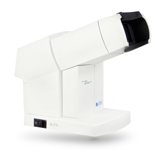
Introduction Instrument Components, Patient Side Forehead Rest Patient Visor Calibration Cap Patient Eyepiece Power Cord Voltage Selector Indicator Power Switch Patient Response Button Power Cord Inlet Instrument Components, Operator Side Operator Control Panel Operator Buttons Operator LCD (Blue) Cancel/Backup Operator LCD Display Button (Green) Contrast Adjustment Buttons... -
Page 18: Instrument Components
Introduction Instrument Components The instrument has seven Buttons to control the operation of the instrument, located adjacent to the Operator’s Liquid Crystal Display (LCD). • Four BLUE Operator Buttons along the left side of the Operator LCD Display • A GREEN Cancel/Backup Button below the four BLUE Buttons •... -
Page 19: Patient Video Screen Patterns
Introduction Patient Video Screen Patterns Humphrey FDT User Manual 2660021149532 Rev. B 2015-11... - Page 20 Introduction Humphrey FDT User Manual 2660021149532 Rev. B 2015-11...
-
Page 21: Operation
Operation (3) Operation Unpacking Personnel using this instrument should read and understand the operating instructions manual before using the instrument. Interpretation of the results should be performed only by appropriately trained eyecare professionals. Open the shipping box by carefully cutting the packing tape securing the top flaps of the box. -
Page 22: Preparation For Use And Power On
Operation Paper Access Door Paper Access Door Finger Tab Finger Tab Preparation For Use and Power On Patient Side Serial Number Location Operator Side While facing the Patient Side of the FDT instrument, tilt the instrument to plug the Patient Response Button connector into the small round connector jack. - Page 23 Operation voltage CAUTION: VERIFY OPERATING VOLTAGE SELECTION — selector switch is normally set to the appropriate operating voltage before shipment (115 V or 230 V). Before applying power to the FDT, verify that the Voltage Selector Indicator adjacent to the O/I Power Switch displays the appropriate operating voltage (115 V or 230 V) in your region.
- Page 24 Operation Power Switch Fuse Drawer Cover Fuse Carrier/Voltage Selector Make sure that the two fuses are inserted so that they are closest to the protruding metal flanges. Selected Voltage Plug the appropriate approved Power Cord into the Power Cord Inlet on the operator’s right-hand side and plug the opposite end into a standard power outlet.
- Page 25 Operation Power Cord Inlet Power Switch To turn the instrument ON, switch the Power Switch (O/I), adjacent to the power connector, to the ON (I) position. The instrument will perform internal self-diagnostic checks and after approximately 15 seconds, two double beeps will sound and the FDT MAIN MENU will appear on the Operator LCD Display.
-
Page 26: Preparing For A Patient Test
Operation Preparing for a Patient Test Remove the CALIBRATION CAP from the Patient Eyepiece. Replace the calibration cap on the Patient Eyepiece when the instrument is not in use to minimize the accumulation of dust and debris in the Patient Eyepiece. Select RUN PATIENT TESTS from the FDT MAIN MENU to prepare for a SCREENING C-20 TEST, SCREENING N-30 TEST, THRESHOLD C-20 TEST or a THRESHOLD N-30 TEST. -
Page 27: Enter The Patient's Age
Operation Enter the Patient’s Age The unit will start with an AGE of 50 years. Select +10 YEARS (TOP BLUE Button) to increase the AGE by 10 year increments (e.g. to 60, 70, and so on). Select -10 YEARS (2nd BLUE Button from the top) to decrease the AGE by 10 year increments. -
Page 28: Explain The Test Procedure To The Patient
Operation the test if their lenses or contact lenses are tinted or change contrast based on lighting conditions (photochromatic). Tests may be taken with bifocal or progressive lenses (unless the progressive lenses have more than 3D equivalent sphere distance correction). Explain the Test Procedure to the Patient “A demonstration of the test is running now. -
Page 29: Running A Screening Or Threshold Patient Test
Operation FREQUENCY DOUBLING TECHNOLOGY MAIN MENU RUN PATIENT TESTS RUN DEMONSTRATION ADVANCE PAPER UTILITIES MENU 24 JUN 1997 04:08 PM Be sure to prepare the patient as described above before running a practice test. Running a Screening or Threshold Patient Test Select either SCREENING TEST MENU or THRESHOLD TEST MENU from the RIGHT EYE TEST MENU. - Page 30 Operation 3-10 Note: The Operator LCD Display will indicate if there is too much ambient light to perform a reliable test. Lower the room lighting or change the test location until suitable test conditions are achieved. Also, if the Patient Response Button is not connected or the Patient Visor is in the wrong eye position, this will be indicated on the Operator LCD Display.
- Page 31 Operation 3-11 False Negative and False Positive catch trial presentations are indicated by the symbols (+) & (-) on the operator LCD so they can be distinguished from regular teststimulus presentations. Note: You can PAUSE or RE-START the test by pressing the GREEN Button at any time during the test.
-
Page 32: Displaying And Printing The Test Results
Operation 3-12 Displaying and Printing the Test Results You can both view the results on the Operator LCD Display and print them out from the test results menu. At the end of a test, the results will be automatically printed (default set-up is automatic printing) and then the test results menu will automatically appear on the Operator LCD Display. -
Page 33: Understanding The Screening C-20 And N-30 Test Results
Operation 3-13 Understanding the Screening C-20 and N-30 Test Results A plot of the 17 visual field locations tested will be printed (see samples on the following pages) and displayed on the Operator LCD Display for the supra-threshold SCREENING C-20 TEST for each eye tested. There are 19 visual field locations tested with the SCREENING N-30 TEST. - Page 34 Operation 3-14 Because the FDT Screening N-30-1 (or C-20-1) and N-30-5 (or C-20-5) programs utilize different baseline normal contrast levels, they also differ in how they flag (shade) test locations as being outside normal limits. With the N-30-1 (or C-20-1) test, points are initially flagged when they reach the P<1% probability significance level (i.e.
-
Page 35: Understanding The Threshold C-20 And N-30 Test Results
Operation 3-15 Understanding the Threshold C-20 and N-30 Test Results A plot of the 17 or 19 visual field locations tested will be printed (see samples on the following pages) and a combination plot will be displayed on the Operator LCD Display for the THRESHOLD C-20 and N-30 TEST for each eye tested. - Page 36 Operation 3-16 FALSE POSITIVE ERRORS - The ratio of the number of times the patient responded to a “pause” in the testing sequence (i.e., with no target presented) versus the total number of “pauses” in the testing sequence. Six FALSE POSITIVE catch trials will be randomly presented for each eye in the C-20 TEST, eight in the N-30 TEST.
- Page 37 Operation 3-17 When the PSD value is GREATER than that of 95% of normal FDT fields, the percentile probability is given (P < 5%, P < 2%, P < 1%, or P < 0.5%) on the Operator LCD Display and on the printed report. Pattern Deviation plots are displayed and printed with Threshold test results.
-
Page 38: Screening C-20 Test Result Sample
Operation 3-18 Screening C-20 Test Result Sample Humphrey FDT User Manual 2660021149532 Rev. B 2015-11... -
Page 39: Threshold C-20 Test Results Sample
Operation 3-19 Threshold C-20 Test Results Sample Humphrey FDT User Manual 2660021149532 Rev. B 2015-11... -
Page 40: Threshold N-30 Test Results Sample
Operation 3-20 Threshold N-30 Test Results Sample Humphrey FDT User Manual 2660021149532 Rev. B 2015-11... -
Page 41: Calibration And Set-Up
Calibration and Set-up (4) Calibration and Set-up Calibration and Set-up The UTILITIES MENU on the FDT MAIN MENU should not be needed unless calibration or a change of the instrument set-up defaults is needed (set-ups are set to defaults and date and time (EST) have been pre-set). -
Page 42: Set-Up Instrument Options
Calibration and Set-up Select NEXT CHOICE (3rd Operator Button from the top) to select the clock setting you want to change. (s) INCREASE (TOP Operator Button) and (t) DECREASE (2nd Operator Button from the top) to change the setting. Select ACCEPT SETTINGS (BOTTOM Operator Button) when the correct CLOCK settings are displayed. -
Page 43: Calibration
Calibration and Set-up Calibration This instrument does not require scheduled calibration. The instrument calibration is checked each time the instrument is powered ON and at the start of each test to be sure the unit is properly calibrated. If the instrument detects the need for calibration, the Operator LCD Display will display a Needs Calibration warning. -
Page 44: Software Upgrade
Calibration and Set-up Software Upgrade This instrument is designed with the ability to upgrade the operating software. For detailed software upgrade information, reference the software upgrade instructions available from authorized representatives. The current software version is available in the ABOUT FDT SCREEN and on the bottom of the each RESULTS PRINT-OUT. - Page 45 Calibration and Set-up Place the leading edge of the paper onto the metal bar and push it into the unit under the roller bar. The instrument will automatically feed the paper through once you have inserted it far enough. Close the Paper Access Door, being sure the paper is sticking out through the slot in the door.
-
Page 46: Fuse Replacement
• Primer, English only Note: Item part numbers and descriptions are subject to change. To order: In the U.S., call 800-341-6968. Outside the U.S., contact your local Carl Zeiss affiliate or distributor. * ViewFinder Software is a PC-based application that enables the FDT exam to be serially transferred to a local computer running the ViewFinder software. -
Page 47: Cleaning, Disinfection, Sterilization And Disposal
CAUTION: Do not sterilize the instrument or any of its components. Instrument Disposition When it comes time to upgrade the FDT, please contact Carl Zeiss Meditec to inquire about trade-in or upgrade values we may offer. Should you not wish to trade in the instrument, please dispose of it in accordance with local and national electrical and electronic equipment recycling requirements. -
Page 48: Troubleshooting
Calibration and Set-up In accordance with applicable EU guidelines and national regulations at the time at which the product was brought onto the market, the product specified on the consignment note is not to be disposed of via the domestic waste disposal system or communal waste disposal facilities. -
Page 49: Service Information
Technical service support is available during normal business hours on normal business days at the authorized service location listed below. For customers outside of the USA, contact your nearest Carl Zeiss Meditec authorized service location or distributor for assistance. - Page 50 Service Information Humphrey FDT User Manual 2660021149532 Rev. B 2015-11...
-
Page 51: Specifications
Specifications (6) Specifications Instrument Dimensions: 25 cm [10''] wide x 48 cm [19''] deep x 43 cm [17''] high Weight: Less than 9 kg [20 lbs.] Patient display size: 40° horizontal by 40° vertical square Power requirements: 115/230 V~, 50/60 Hz, 0.4/0.2 A, Power Connection: IEC-320 standard power inlet connector for worldwide use Power Cord:... -
Page 52: Reliability Indices
Specifications Reliability Indices: • Fixation Monitoring: Heijl-Krakau fixation monitor • Catch trial contrast: 6 dB (~ 50%) • 3 catch trials in SCREENING C-20 and N-30 TESTS • 6 catch trials in THRESHOLD C-20 and N-30 TESTS • Presentation Order: Pseudo-Random •... - Page 54 Carl Zeiss Meditec, Inc. Carl Zeiss Meditec AG 5160 Hacienda Drive Goeschwitzer Strasse 51-52 Dublin, CA 94568 07745 Jena Germany Toll Free: 1 800 341 6968 Phone: +49 36 41 22 03 33 Phone: +1 925 557 4100 Fax: +49 36 41 22 01 12 2660021149532 Rev.
Need help?
Do you have a question about the Humphrey FDT 710 and is the answer not in the manual?
Questions and answers