
Related Manuals for Zeiss OPMI VISU 210


Summary of Contents for Zeiss OPMI VISU 210
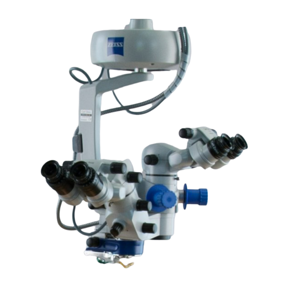
- Page 1 MISU241 OPMI VISU 210 ® on S8, S81, S88 Suspension Systems Instructions for use G-30-1530-en Issue 1.0 Printed on 19. 04. 2004...
-
Page 2: Key To Symbols
The square indicates situations which may lead to malfunction, defects, collision or damage of the instrument. Note: The hand indicates hints on the use of the instrument or other tips for the user. ® OPMI ® OPMI is a registered trademark of Carl Zeiss. -
Page 3: Table Of Contents
MISU241 Contents – Key to symbols Functions at a glance – VISU 210 surgical microscope – Illumination systems – S88 floor stand – S8 ceiling mount – S81 ceiling mount Safety – Directives and standards – Notes on installation and use –... - Page 4 MISU241 – Stand base with column – Connection panel – Suspension arm – Display field with control keys – Instrument tray (option) S8 Ceiling Mount – Intended use – Description of the modules – Design – Handle – Power switch with connector (option) –...
- Page 5 MISU241 Preparations Attaching the equipment – Mounting the surgical microscope – Mounting the tube, the eyepieces and the objective lens – Changing the microscope accessories Connections – Connecting the surgical microscope – Connecting the S light guide – Strain relief device on S88 floor stand –...
- Page 6 – Changing the xenon lamp module – Magnifications / Fields of view – Care of the unit – Sterilization – Disinfecting the control keys – Auxiliaries from Zeiss – Ordering data – Spare parts – Accessories Technical data – Technical data –...
-
Page 7: Functions At A Glance
MISU241 Functions at a glance Functions at a glance VISU 210 surgical microscope Illumination systems S88 floor stand S8 ceiling mount S81 ceiling mount G-30-1530-en OPMI® VISU 210 on S8, S81, S88 Suspension Systems Issue 1.0 Printed on 19. 04. 2004... -
Page 8: Visu 210 Surgical Microscope
MISU241 Functions at a glance VISU 210 surgical microscope Resetting the X-Y coupling and focus to their initial posi- tions Adjusting the interpupillary distance page 64 Adjusting the eyecups Setting your prescription Handgrip page 58 Display of the magnification factor of the zoom system page 58 Changing the magnification on assistant's microscope page 62... - Page 9 MISU241 Functions at a glance 14 15 16 17 G-30-1530-en OPMI® VISU 210 on S8, S81, S88 Suspension Systems Issue 1.0 Printed on 19. 04. 2004...
- Page 10 MISU241 Functions at a glance G-30-1530-en OPMI® VISU 210 on S8, S81, S88 Suspension Systems Issue 1.0 Printed on 19. 04. 2004...
-
Page 11: Illumination Systems
MISU241 Functions at a glance Illumination systems Halogen illumination system Closed flap: main lamp is on - open flap: backup lamp Page 48 is on Selecting a filter Page 48 Opening the lamp module Page 48 Manual selection of backup lamp Page 48 Xenon illumination system Selecting a filter... -
Page 12: S88 Floor Stand
MISU241 Functions at a glance S88 floor stand Control panel page 176 Lamp housing for halogen illumination (xenon illumi- page 80 nation) Releasing the magnetic brakes of the suspension Page 38 system Limiting the suspension arm's downward movement Page 70 Removing/mounting the coupling for the surgical mi- Page 54 croscope... - Page 13 MISU241 Functions at a glance 8 9 10, 11, 12 G-30-1530-en OPMI® VISU 210 on S8, S81, S88 Suspension Systems Issue 1.0 Printed on 19. 04. 2004...
-
Page 14: S8 Ceiling Mount
MISU241 Functions at a glance S8 ceiling mount Locking the suspension arm in its horizontal position Page 36 Releasing the magnetic brakes of the suspension system Page 36 Balance setting Page 60 Lamp housing with halogen or xenon illumination Page 30 Control panel (rotatable through 180°) Page 66 Connecting a foot control panel or hand switch, con-... - Page 15 MISU241 Functions at a glance G-30-1530-en OPMI® VISU 210 on S8, S81, S88 Suspension Systems Issue 1.0 Printed on 19. 04. 2004...
-
Page 16: S81 Ceiling Mount
MISU241 Functions at a glance S81 ceiling mount Locking the suspension arm in its horizontal position Page 34 Releasing the magnetic brakes of the suspension system Page 34 Balance setting Page 56 Lamp housing with halogen or xenon illumination Page 30 Control panel (rotatable through 180°) Page 62 Option: Hand control panel socket for ceiling track mount Page 32... - Page 17 MISU241 Functions at a glance G-30-1530-en OPMI® VISU 210 on S8, S81, S88 Suspension Systems Issue 1.0 Printed on 19. 04. 2004...
- Page 18 MISU241 Functions at a glance G-30-1530-en OPMI® VISU 210 on S8, S81, S88 Suspension Systems Issue 1.0 Printed on 19. 04. 2004...
-
Page 19: Safety
MISU241 Safety Safety Directives and standards Notes on installation and use When using a fundus imaging system (e.g. BIOM 3) Phototoxic retinal injury in eye surgery Safety devices of the suspension systems Warning labels and notes G-30-1530-en OPMI® VISU 210 on S8, S81, S88 Suspension Systems Issue 1.0 Printed on 19. -
Page 20: Directives And Standards
MISU241 Safety The instrument described in this manual has been developed and tested in accordance with Carl Zeiss safety standards and with national and in- ternational regulations. A high degree of instrument safety is thus en- sured. We would like to inform you on the safety aspects involved in operating the instrument. -
Page 21: Notes On Installation And Use
Use this instrument only for the applications described. • Only use the instrument with the accessories supplied. Should you wish to use other accessory equipment, make sure that Carl Zeiss or the equipment manufacturer has certified that its use will not impair the safety of instrument. - Page 22 MISU241 Safety • Only personnel who have undergone training and instruction are al- lowed to use this instrument. It is the responsibility of the customer or institution operating the equipment to train and instruct all staff using the equipment. • Keep the user's manuals where they are easily accessible at all times for the persons operating the instrument.
- Page 23 Xenon lamps feature high luminance and a spectrum resembling that of natural daylight. Therefore, only special xenon lamps approved by Carl Zeiss must be used in ophthalmology. • Any kind of radiation has a detrimental effect on biological tissue.This also applies to the light illuminating the surgical field.
- Page 24 MISU241 Safety S8 ceiling mount • The lift arm is used to move the microscope into position for surgery prior to the surgical procedure. Do not constantly move the lift arm up and down, since a thermal cut- out will then automatically deactivate the drive motor. If this occurs, the lift arm cannot be moved until the motor has cooled down.
-
Page 25: When Using A Fundus Imaging System (E.g. Biom 3)
MISU241 Safety When using a fundus imaging system (e.g. BIOM 3) When using a fundus imaging system (e.g. BIOM 3 from the company Oc- ulus) which is usually installed between the surgical microscope and the patient, make sure that the patient is neither put at risk nor injured by the motorized focusing system or the movement of the suspension system arm. - Page 26 MISU241 Safety In the following, comments on these aspects are given and a description of how Carl Zeiss, as a manufacturer, makes allowance for them in its systems. Illumination characteristics (spectral composition) Studies on exposure of the eye to light of varying spectral composition date back to the early 1950s.
- Page 27 Also, the surrounding light sources should not cause addi- tional strain to the patient's eye. Carl Zeiss has provided an answer to this problem in the form of a swing- in retinal protection device for insertion into the beam path of the surgical microscope.
- Page 28 MISU241 Safety In conclusion Carl Zeiss recommends: – Use of the GG 475 retina protection filter. – Reduction of the illumination of the surgical area to the extent required for the patient's safety and for clear microscopic visualization. – Tilting of the microscope body as required.
- Page 29 MISU241 Safety G-30-1530-en OPMI® VISU 210 on S8, S81, S88 Suspension Systems Issue 1.0 Printed on 19. 04. 2004...
-
Page 30: Safety Devices Of The Suspension Systems
MISU241 Safety Safety devices of the suspension systems 1 Release bar Allows non-sterile persons to release the magnetic brakes of the sus- pension system. 2 Adjustment screw for limiting the downward travel Use this screw to set the minimum vertical distance (working distance) from the surgical field. - Page 31 MISU241 Safety G-30-1530-en OPMI® VISU 210 on S8, S81, S88 Suspension Systems Issue 1.0 Printed on 19. 04. 2004...
- Page 32 MISU241 Safety Xenon illumination system 1 Selecting the backup lamp The lamp module contains two xenon lamps. The second lamp is used as a backup lamp which has to be swung into the illumination beam path when the first lamp fails. If the xenon lamp fails, open the lamp module as follows: Press button (5).
- Page 33 MISU241 Safety G-30-1530-en OPMI® VISU 210 on S8, S81, S88 Suspension Systems Issue 1.0 Printed on 19. 04. 2004...
- Page 34 MISU241 Safety Halogen illumination system 1 Flap The flap is the mechanical indicator for the operating status of the hal- ogen lamps. – When the flap is closed, the main lamp is operative. – When the flap is open, the main lamp has failed. The backup lamp is on.
- Page 35 MISU241 Safety G-30-1530-en OPMI® VISU 210 on S8, S81, S88 Suspension Systems Issue 1.0 Printed on 19. 04. 2004...
- Page 36 MISU241 Safety Manual function 1 Manual key The Manual key permits you to switch to manual operation. The mo- torized control functions of the surgical microscope are deactivated. The lamp brightness is automatically adjusted to a fixed setting, the value being shown in the first display section. When the manual mode is activated, the yellow LED is lit and the word "MANUAL"...
- Page 37 MISU241 Safety G-30-1530-en OPMI® VISU 210 on S8, S81, S88 Suspension Systems Issue 1.0 Printed on 19. 04. 2004...
-
Page 38: Warning Labels And Notes
If any label is missing on your instrument or has become illegible, please contact us or one of our authorized representatives. We will supply the missing labels. OPMI VISU 210 G-30-1530-en OPMI® VISU 210 on S8, S81, S88 Suspension Systems Issue 1.0... - Page 39 MISU241 Safety Illumination systems Superlux Eye GG 475 G-30-1530-en OPMI® VISU 210 on S8, S81, S88 Suspension Systems Issue 1.0 Printed on 19. 04. 2004...
- Page 40 MISU241 Safety S88 floor stand G-30-1530-en OPMI® VISU 210 on S8, S81, S88 Suspension Systems Issue 1.0 Printed on 19. 04. 2004...
- Page 41 MISU241 Safety S8 ceiling mount G-30-1530-en OPMI® VISU 210 on S8, S81, S88 Suspension Systems Issue 1.0 Printed on 19. 04. 2004...
- Page 42 MISU241 Safety S81 ceiling mount G-30-1530-en OPMI® VISU 210 on S8, S81, S88 Suspension Systems Issue 1.0 Printed on 19. 04. 2004...
-
Page 43: Description
MISU241 Description Description VISU 210 surgical microscope Intended use Description of the modules Illumination system Controls, displays, connections Binocular tubes and eyepieces Illumination systems - halogen and xenon Halogen illumination system Xenon illumination system S88 floor stand Intended use Description of the modules Design Stand base with column Connection panel... - Page 44 MISU241 Description Intended use Description of the modules Design Power switch, connector and socket (option) Suspension arm Display field with control keys VISU 210 surgical microscope on S88 floor stand Intended use Design VISU 210 surgical microscope on S8 ceiling mount Intended use Design VISU 210 surgical microscope on S81 ceiling mount...
- Page 45 MISU241 Description G-30-1530-en OPMI® VISU 210 on S8, S81, S88 Suspension Systems Issue 1.0 Printed on 19. 04. 2004...
-
Page 46: Visu 210 Surgical Microscope
MISU241 Description VISU 210 surgical microscope Intended use Note: The illumination system of the VISU 160 surgical microscope always con- tains a UV blocking filter. The use of this filter ensures that the illumination intensity lies below 50 µW/cm in the range between 305 nm and 400 nm. This helps the surgeon to reduce the risk of phototoxic retinal injury in the patient. - Page 47 MISU241 Description G-30-1530-en OPMI® VISU 210 on S8, S81, S88 Suspension Systems Issue 1.0 Printed on 19. 04. 2004...
- Page 48 MISU241 Description 2 Support arm for surgical microscope The support arm incorporates a tilt device. This allows the viewing di- rection of the surgical microscope to be adapted to the requirements of the surgical field. Using the knob for fine tilt, you can position the surgical microscope in a range from +180°...
- Page 49 MISU241 Description G-30-1530-en OPMI® VISU 210 on S8, S81, S88 Suspension Systems Issue 1.0 Printed on 19. 04. 2004...
- Page 50 MISU241 Description 6 Assistant's microscope 0° The assistant's microscope is an integral part of the VISU 210 surgical microscope, i.e. it cannot be separated from the main microscope. The assistant sees the same image as the main surgeon. The system's excellent image quality is also available to the assistant. The assistant's microscope has two working positions.
- Page 51 MISU241 Description G-30-1530-en OPMI® VISU 210 on S8, S81, S88 Suspension Systems Issue 1.0 Printed on 19. 04. 2004...
- Page 52 MISU241 Description G-30-1530-en OPMI® VISU 210 on S8, S81, S88 Suspension Systems Issue 1.0 Printed on 19. 04. 2004...
-
Page 53: Illumination System
MISU241 Description Illumination system The illumination system has been designed for use in ophthalmology. A light guide directs the light from the light source in the suspension system to the surgical microscope. A retinal protection device is provided to protect the patient's eye from photoretinitis. - Page 54 MISU241 Description 6° illumination The 6° illumination can be faded out continuously. The result is a signifi- cantly reduced illumination reflex on the cornea. Despite this, the image provides high contrast and a high information content. A slight opening (approx. 1/4) of the 6°- illumination is ideal for cataract surgery.
- Page 55 MISU241 Description + 6° + 2° G-30-1530-en OPMI® VISU 210 on S8, S81, S88 Suspension Systems Issue 1.0 Printed on 19. 04. 2004...
-
Page 56: Controls, Displays, Connections
MISU241 Description Controls, displays, connections 1 Securing screw 2 X-Y coupling 3 Actuator button – recenters the X-Y coupling. – resets the focus to its initial position in the focusing range – sets the zoom system to a preselected magnification factor, if the XYZ-RES function has been selected. - Page 57 MISU241 Description G-30-1530-en OPMI® VISU 210 on S8, S81, S88 Suspension Systems Issue 1.0 Printed on 19. 04. 2004...
- Page 58 MISU241 Description 8 Dust cover 9 Handgripps for releasing the magnetic brakes of the suspension sys- Only in combination with suspension systems with magnetic brakes. – Handgrip turned Magnetic brakes are unlocked, the in- strument can be moved as required. –...
- Page 59 MISU241 Description G-30-1530-en OPMI® VISU 210 on S8, S81, S88 Suspension Systems Issue 1.0 Printed on 19. 04. 2004...
- Page 60 MISU241 Description 12 DeepView button Permits the selection of different modes. When you switch on the system, the mode for transmission optimization is set by default. This mode is recommended for viewing the posterior segment of the eye. Press the button to activate the mode for depth of field optimization. The green LED in the button is lit.
- Page 61 MISU241 Description G-30-1530-en OPMI® VISU 210 on S8, S81, S88 Suspension Systems Issue 1.0 Printed on 19. 04. 2004...
- Page 62 MISU241 Description 17 Locking screw for locking the coobservation tube within the 12° range of rotation. 18 Binocular tube of the assistant's microscope 19 Focusing knob for focusing the assistant's microscope independently of the main sur- geon. 20 Five-step manual magnification changer 21 Locking screw for locking the assistant's microscope within the 15°...
- Page 63 MISU241 Description 20 21 G-30-1530-en OPMI® VISU 210 on S8, S81, S88 Suspension Systems Issue 1.0 Printed on 19. 04. 2004...
-
Page 64: Binocular Tubes And Eyepieces
MISU241 Description Binocular tubes and eyepieces You can mount a 180° tiltable tube or a 45° inclined tube on the VISU 210 surgical microscope as required. 180° tiltable tube 1 PD adjustment knob The correct position has been reached when the two eyepiece images merge into one. - Page 65 MISU241 Description G-30-1530-en OPMI® VISU 210 on S8, S81, S88 Suspension Systems Issue 1.0 Printed on 19. 04. 2004...
- Page 66 MISU241 Description Widefield eyepieces with magnetic coupling Note: When you remove these eyepieces from the tube, please note that they are fitted with a magnetic coupling. When mounted, the eyepieces display a very weak magnetic field, so that the usual rules for the handling of mag- nets must only be observed with eyepieces which have not been mounted on the microscope: •...
- Page 67 MISU241 Description G-30-1530-en OPMI® VISU 210 on S8, S81, S88 Suspension Systems Issue 1.0 Printed on 19. 04. 2004...
-
Page 68: Illumination Systems - Halogen And Xenon
MISU241 Description Illumination systems - halogen and xenon Halogen illumination system The ceiling mount is equipped with an illumination system for fiber illumi- nation. The lamp housing contains a backup lamp which is automatically swung into the illumination beam path when the first lamp fails. If required, the illumination system can be equipped with a second lamp housing so that two separate illumination systems are available for fiber illumination. - Page 69 MISU241 Description G-30-1530-en OPMI® VISU 210 on S8, S81, S88 Suspension Systems Issue 1.0 Printed on 19. 04. 2004...
- Page 70 MISU241 Description 7 Brightness control Brightness can be adjusted using the two keys (7) on the control panel. Note: With suspension systems with two lamp housings, you can also adjust the brightness of lamp 1 or 2 by pressing the appropriate key on the foot control panel.
- Page 71 MISU241 Description G-30-1530-en OPMI® VISU 210 on S8, S81, S88 Suspension Systems Issue 1.0 Printed on 19. 04. 2004...
-
Page 72: Xenon Illumination System
MISU241 Description Xenon illumination system The suspension system is equipped with a xenon illumination system for fiber illumination. The xenon lamp generates light whose spectrum re- sembles that of natural daylight. Regardless of the brightness setting, the color temperature of the light always remains the same. Normal daylight film without any additional conversion filters can therefore be used for photographic documentation. - Page 73 MISU241 Description G-30-1530-en OPMI® VISU 210 on S8, S81, S88 Suspension Systems Issue 1.0 Printed on 19. 04. 2004...
- Page 74 MISU241 Description 6 Brightness control You can adjust the brightness using the two control keys on the control panel. Note: The brightness of the xenon lamp can also be adjusted by pressing the appropriate buttons on the foot control panel. 7 Yellow indicator lamp Lights when the lamp has failed, or if the lamp module is defective.
- Page 75 MISU241 Description G-30-1530-en OPMI® VISU 210 on S8, S81, S88 Suspension Systems Issue 1.0 Printed on 19. 04. 2004...
-
Page 76: S88 Floor Stand
S88 floor stand Intended use The floor stand is a carrier system for Zeiss surgical microscopes for al- most all surgical disciplines. It is used to power and control the motorized functions of a surgical microscope. The hallmarks of the floor stand are its superb mobility and easy operation. -
Page 77: Description Of The Modules
MISU241 Description Description of the modules The floor stand comprises an articulated arm, a stand column and a stand base. The articulated arm comprises a carrier arm and a suspension arm. The carrier arm contains the control unit with all electrical supply systems required for the control of a motorized surgical microscope. -
Page 78: Design
MISU241 Description Design 1 Control unit 2 Carrier arm 3 Lamp housing (optionally with halogen or xenon illumination 4 Suspension arm 5 Stand base G-30-1530-en OPMI® VISU 210 on S8, S81, S88 Suspension Systems Issue 1.0 Printed on 19. 04. 2004... - Page 79 MISU241 Description G-30-1530-en OPMI® VISU 210 on S8, S81, S88 Suspension Systems Issue 1.0 Printed on 19. 04. 2004...
- Page 80 Warning! When using xenon illumination, only operate the system with special xenon lamps approved by Carl Zeiss. If any other than Carl Zeiss-ap- proved xenon lamps are used, there is the risk of severe injury to the pa- tient's eye.
- Page 81 MISU241 Description G-30-1530-en OPMI® VISU 210 on S8, S81, S88 Suspension Systems Issue 1.0 Printed on 19. 04. 2004...
-
Page 82: Stand Base With Column
MISU241 Description Stand base with column 1 Handle for moving the stand. 2 Support for hanging up the foot control panel during transport. 3 Cable support (2x) for winding up the power cord and the cable of the foot control panel. 4 Locking pedal Press once to lock the stand in position. - Page 83 MISU241 Description G-30-1530-en OPMI® VISU 210 on S8, S81, S88 Suspension Systems Issue 1.0 Printed on 19. 04. 2004...
-
Page 84: Connection Panel
MISU241 Description Connection panel 1 Remote control socket for triggering an AUX signal, e.g. to switch on/off an external device with 24V/0.5A max. 2 Connector for switching component Connection possibility for: a foot control panel, a hand control panel or an operating chair with an appropriate foot switch. - Page 85 MISU241 Description – connecting cable for foot control panel, hand control panel or op- erating chair with an appropriate footswitch. G-30-1530-en OPMI® VISU 210 on S8, S81, S88 Suspension Systems Issue 1.0 Printed on 19. 04. 2004...
-
Page 86: Suspension Arm
MISU241 Description Suspension arm 1 Locking cap of arm cover – To open: turn 90° to the left or right. – To close: press down and turn 90° to the left or right. 2 Adjustment screw for limiting the downward movement of the arm Use this screw to set the minimum vertical distance (working distance) to the surgical field. - Page 87 MISU241 Description G-30-1530-en OPMI® VISU 210 on S8, S81, S88 Suspension Systems Issue 1.0 Printed on 19. 04. 2004...
-
Page 88: Display Field With Control Keys
MISU241 Description Display field with control keys The display and control panel is integrated in the control unit. Basic mode The surgical microscope on the suspension system can be controlled ei- Halogen ther manually or electronically. The control software required for elec- tronic control is installed in the electronics box of the suspension system. - Page 89 MISU241 Description "MODE" key and "STORE" key The "MODE" and "STORE" keys permit you to access the different modes of the user interface. For details, please see the chapter "Operation". "STORE" key You use the "STORE" key, for example, to save the current focus and ®...
-
Page 90: Instrument Tray (Option)
MISU241 Description Instrument tray (option) Note: • The floor stand can be equipped (also subsequently) with an instru- ment carrier (1). Our service department or an authorized person will install the instrument carrier to your stand. The MediLive documentation equipment can be screwed onto this instru- ment carrier. - Page 91 MISU241 Description G-30-1530-en OPMI® VISU 210 on S8, S81, S88 Suspension Systems Issue 1.0 Printed on 19. 04. 2004...
-
Page 92: S8 Ceiling Mount
S8 Ceiling Mount Intended use The S8 ceiling mount is a suspension system for Zeiss surgical micro- scopes. It is used to power and control the motorized functions of the sur- gical microscope. The hallmarks of the S8 ceiling mount are its superb mobility and easy operation. -
Page 93: Description Of The Modules
MISU241 Description Description of the modules The S8 ceiling mount comprises the articulated arm, the suspension arm with the lamp housing, and the control panel. The articulated arm consists of a lift arm and carrier arm. The lift function permits the ceiling mount to be brought into a parking position. A grip is provided for the vertical adjustment of the ceiling mount. -
Page 94: Design
MISU241 Description Design 1 Lift arm 2 Carrier arm 3 Suspension arm 4 Lamp housing (optionally with halogen or xenon illumination) 5 Control unit G-30-1530-en OPMI® VISU 210 on S8, S81, S88 Suspension Systems Issue 1.0 Printed on 19. 04. 2004... - Page 95 MISU241 Description G-30-1530-en OPMI® VISU 210 on S8, S81, S88 Suspension Systems Issue 1.0 Printed on 19. 04. 2004...
- Page 96 Warning! When using xenon illumination, only operate the system with special xenon lamps approved by Carl Zeiss. If any other than Carl Zeiss-ap- proved xenon lamps are used, there is the risk of severe injury to the pa- tient's eye.
- Page 97 MISU241 Description G-30-1530-en OPMI® VISU 210 on S8, S81, S88 Suspension Systems Issue 1.0 Printed on 19. 04. 2004...
-
Page 98: Handle
MISU241 Description Handle A lift mechanism permits you to bring the ceiling mount into a parking po- sition. A handle is provided for this purpose on the ceiling mount. The handle remains within easy reach after the ceiling mount has been moved into the parking position. - Page 99 MISU241 Description G-30-1530-en OPMI® VISU 210 on S8, S81, S88 Suspension Systems Issue 1.0 Printed on 19. 04. 2004...
-
Page 100: Power Switch With Connector (Option)
MISU241 Description Power switch with connector (option) The power switch and the connector can be either installed in the OR, or they can be integrated in the ceiling mount, at the back of the carrier arm (see illustration). 1 Rail The delivery package contains a cable clip which is used to guide the cable of the foot control panel away from the operating table. - Page 101 MISU241 Description G-30-1530-en OPMI® VISU 210 on S8, S81, S88 Suspension Systems Issue 1.0 Printed on 19. 04. 2004...
-
Page 102: Suspension Arm
MISU241 Description Suspension arm 1 Locking cap of arm cover – To open: turn 90° to the left or right. – To close: press down and turn 90° to the left or right. 2 Adjustment screw for limiting the downward movement of the arm Use this screw to set the minimum vertical distance (working distance) to the surgical field. - Page 103 MISU241 Description G-30-1530-en OPMI® VISU 210 on S8, S81, S88 Suspension Systems Issue 1.0 Printed on 19. 04. 2004...
-
Page 104: Display Field With Control Keys
MISU241 Description Display field with control keys The display and control panel is integrated in the control unit. Basic mode The surgical microscope on the suspension system can be controlled ei- Halogen ther manually or electronically. The control software required for elec- tronic control is installed in the electronics box of the suspension system. - Page 105 MISU241 Description "MODE" key and "STORE" key The "MODE" and "STORE" keys permit you to access the different modes of the user interface. For details, please see the chapter "Operation". "STORE" key You use the "STORE" key, for example, to save the current focus and ®...
-
Page 106: S81 Ceiling Mount
S81 ceiling mount Intended use The S81 ceiling mount is a suspension system for Zeiss surgical micro- scopes. It is used to power and control the motorized functions of the sur- gical microscope. The hallmarks of the S81 ceiling mount are its superb mobility and easy operation. -
Page 107: Description Of The Modules
MISU241 Description Description of the modules The S81 ceiling mount comprises a column, the carrier arm and the sus- pension arm. The suspension arm with the lamp housing and the control panel is mounted on the carrier arm. The control panel can be turned through 180°;... -
Page 108: Design
MISU241 Description Design 1 Column 2 Carrier arm 3 Suspension arm 4 Lamp housing (optionally with halogen or xenon illumination) 5 Control unit G-30-1530-en OPMI® VISU 210 on S8, S81, S88 Suspension Systems Issue 1.0 Printed on 19. 04. 2004... - Page 109 MISU241 Description G-30-1530-en OPMI® VISU 210 on S8, S81, S88 Suspension Systems Issue 1.0 Printed on 19. 04. 2004...
- Page 110 Warning! When using xenon illumination, only operate the system with special xenon lamps approved by Carl Zeiss. If any other than Carl Zeiss-ap- proved xenon lamps are used, there is the risk of severe injury to the pa- tient's eye.
- Page 111 MISU241 Description G-30-1530-en OPMI® VISU 210 on S8, S81, S88 Suspension Systems Issue 1.0 Printed on 19. 04. 2004...
-
Page 112: Power Switch, Connector And Socket (Option)
MISU241 Description Power switch, connector and socket (option) The connector and socket can be either installed in the OR, or they can be integrated in the ceiling mount, at the back of the carrier arm (see illus- tration). 1 Rail The delivery package contains a cable clip which is used to guide the cable of the foot control panel away from the operating table. - Page 113 MISU241 Description G-30-1530-en OPMI® VISU 210 on S8, S81, S88 Suspension Systems Issue 1.0 Printed on 19. 04. 2004...
-
Page 114: Suspension Arm
MISU241 Description Suspension arm 1 Locking cap of arm cover – To open: turn 90° to the left or right. – To close: press down and turn 90° to the left or right. 2 Adjustment screw for limiting the downward movement of the arm Use this screw to set the minimum vertical distance (working distance) to the surgical field. - Page 115 MISU241 Description G-30-1530-en OPMI® VISU 210 on S8, S81, S88 Suspension Systems Issue 1.0 Printed on 19. 04. 2004...
-
Page 116: Display Field With Control Keys
MISU241 Description Display field with control keys The display and control panel is integrated in the control unit. Basic mode The surgical microscope on the suspension system can be controlled ei- Halogen ther manually or electronically. The control software required for elec- tronic control is installed in the electronics box of the suspension system. - Page 117 MISU241 Description "MODE" key and "STORE" key The "MODE" and "STORE" keys permit you to access the different modes of the user interface. For details, please see the chapter "Operation". "STORE" key You use the "STORE" key, for example, to save the current focus and ®...
-
Page 118: Visu 210 Surgical Microscope On S88 Floor Stand
MISU241 Description VISU 210 surgical microscope on S88 floor stand Intended use The VISU 210 surgical microscope has been designed for surgical proce- dures in the field of ophthalmology, i.e. the microscope meets the special requirements of this discipline. The S88 floor stand powers and controls the motorized functions of the VISU 210 surgical microscope. - Page 119 MISU241 Description G-30-1530-en OPMI® VISU 210 on S8, S81, S88 Suspension Systems Issue 1.0 Printed on 19. 04. 2004...
-
Page 120: Visu 210 Surgical Microscope On S8 Ceiling Mount
MISU241 Description VISU 210 surgical microscope on S8 ceiling mount Intended use The VISU 210 surgical microscope has been designed for surgical proce- dures in the field of ophthalmology, i.e. the microscope meets the special requirements of this discipline. The S8 ceiling mount powers and controls the motorized functions of the VISU 210 surgical microscope. - Page 121 MISU241 Description G-30-1530-en OPMI® VISU 210 on S8, S81, S88 Suspension Systems Issue 1.0 Printed on 19. 04. 2004...
-
Page 122: Visu 210 Surgical Microscope On S81 Ceiling Mount
MISU241 Description VISU 210 surgical microscope on S81 ceiling mount Intended use The VISU 210 surgical microscope has been designed for surgical proce- dures in the field of ophthalmology, i.e. the microscope meets the special requirements of this discipline. The S81 ceiling mount powers and controls the motorized functions of the VISU 210 surgical microscope. - Page 123 MISU241 Description G-30-1530-en OPMI® VISU 210 on S8, S81, S88 Suspension Systems Issue 1.0 Printed on 19. 04. 2004...
-
Page 124: Foot Control Panel (Option)
MISU241 Description Foot control panel (option) Intended use The foot control panel permits you to control 14 different functions of a suspension system or surgical microscope, provided these functions are part of your configuration (suspension system, surgical microscope). The assignment of the functions to the controls of the foot control panel is shown on the next page. - Page 125 MISU241 Description G-30-1530-en OPMI® VISU 210 on S8, S81, S88 Suspension Systems Issue 1.0 Printed on 19. 04. 2004...
- Page 126 MISU241 Description The illustration shows the standard assignment of functions to the foot control panel. On request, our service staff can change the assignment of the focus/zoom functions and that of button (10). 1 Joystick for X-Y coupling 2 Reducing the lamp brightness 3 Recentering of the X-Y coupling and focus starting position (optional: control of Stereo Digital Inverter IIe / 3e from the company Oculus).
-
Page 127: Preparations
MISU241 Preparations Preparations Attaching the equipment Mounting the surgical microscope Mounting the tube, the eyepieces and the objective lens Changing the microscope accessories Connections Connecting the surgical microscope Connecting the S light guide Strain relief device on S88 floor stand Connecting the S88 floor stand Relocating the system Adjusting the system - S88 floor stand... -
Page 128: Attaching The Equipment
MISU241 Preparations Attaching the equipment Mounting the surgical microscope Warning! The maximum weight of the microscope including accessories must not exceed 20 kg! • Leave the suspension arm locked in its horizontal position until you – have mounted and secured the complete equipment, –... - Page 129 MISU241 Preparations G-30-1530-en OPMI® VISU 210 on S8, S81, S88 Suspension Systems Issue 1.0 Printed on 19. 04. 2004...
- Page 130 MISU241 Preparations • Screw in the securing screw (7) and tighten it firmly . The securing screw (7) must go into the groove (9). This is ensured when the secu- ring screw is flush with the outer surface of the coupling. •...
- Page 131 MISU241 Preparations G-30-1530-en OPMI® VISU 210 on S8, S81, S88 Suspension Systems Issue 1.0 Printed on 19. 04. 2004...
-
Page 132: Mounting The Tube, The Eyepieces And The Objective Lens
MISU241 Preparations Mounting the tube, the eyepieces and the objective lens Note: Always use the assistant's microscope with the associated binocular coo- bservation tube (shown in the illustration). If you use a different tube, this will give you an inverted image. •... - Page 133 MISU241 Preparations G-30-1530-en OPMI® VISU 210 on S8, S81, S88 Suspension Systems Issue 1.0 Printed on 19. 04. 2004...
- Page 134 MISU241 Preparations Warning! • Before every use and after re-equipping the system, make sure that the two binocular tubes (3 and 11) are securely locked in position. • Make sure that the following components are firmly tightened: – securing screws (6 and 8) and –...
- Page 135 MISU241 Preparations G-30-1530-en OPMI® VISU 210 on S8, S81, S88 Suspension Systems Issue 1.0 Printed on 19. 04. 2004...
-
Page 136: Changing The Microscope Accessories
MISU241 Preparations Changing the microscope accessories You can change the microscope accessories in reverse order to that de- scribed before. Please observe the following: • Turn off the unit at the power switch before changing any accessories. • Bring the suspension arm in a position convenient for you and tighten friction adjustment knob (1). - Page 137 MISU241 Preparations G-30-1530-en OPMI® VISU 210 on S8, S81, S88 Suspension Systems Issue 1.0 Printed on 19. 04. 2004...
-
Page 138: Connections
MISU241 Preparations Connections Connecting the surgical microscope • Turn locking cap (1) by a quarter turn to the right or left and pull up cov- er (2). • Plug microscope connector (3) into connector (4) and tighten the se- curing screws on the microscope connector. •... - Page 139 MISU241 Preparations Surgical microscope, shown rotated G-30-1530-en OPMI® VISU 210 on S8, S81, S88 Suspension Systems Issue 1.0 Printed on 19. 04. 2004...
-
Page 140: Strain Relief Device On S88 Floor Stand
MISU241 Preparations Strain relief device on S88 floor stand Note: To prevent inadvertent unplugging of the power cable and of the control element connector, secure the two cables in strain relief device (1). After strain relief device (1) has been mounted, the cables must have the following length: –... - Page 141 MISU241 Preparations 320 mm G-30-1530-en OPMI® VISU 210 on S8, S81, S88 Suspension Systems Issue 1.0 Printed on 19. 04. 2004...
-
Page 142: Connecting The S88 Floor Stand
MISU241 Preparations Connecting the S88 floor stand • Check the voltage indicated at (3). Caution: The voltage of the stand is factory-set to the rated voltage used in the country of destination. The rated voltage indicated at window (3) must cor- respond to the rated voltage available at the site of installation. - Page 143 MISU241 Preparations G-30-1530-en OPMI® VISU 210 on S8, S81, S88 Suspension Systems Issue 1.0 Printed on 19. 04. 2004...
-
Page 144: Relocating The System
MISU241 Preparations Relocating the system Note: As the stand is very easy to maneuver, there is a tendency to underesti- mate its considerable weight. Therefore, move the stand slowly and care- fully! Please observe the following points when relocating the stand: •... - Page 145 MISU241 Preparations G-30-1530-en OPMI® VISU 210 on S8, S81, S88 Suspension Systems Issue 1.0 Printed on 19. 04. 2004...
-
Page 146: Adjusting The System - S88 Floor Stand
MISU241 Preparations Adjusting the system - S88 floor stand Adjusting the balance setting of the suspension arm • Now perform the balance setting procedure with the complete micro- scope equipment attached! Note: Before you precisely adjust the balance setting of the suspension arm, we recommend performing a coarse balance setting of the arm. - Page 147 MISU241 Preparations G-30-1530-en OPMI® VISU 210 on S8, S81, S88 Suspension Systems Issue 1.0 Printed on 19. 04. 2004...
-
Page 148: Adjusting The Limit Of Downward Movement
MISU241 Preparations Adjusting the limit of downward movement The vertical lift of the suspension arm must be limited in such a way that the patient's safety is also ensured when the microscope is inadvertently lowered. • Loosen the adjustment screw (1) by a few turns. •... - Page 149 MISU241 Preparations G-30-1530-en OPMI® VISU 210 on S8, S81, S88 Suspension Systems Issue 1.0 Printed on 19. 04. 2004...
-
Page 150: Adjusting The System - S8 Ceiling Mount
MISU241 Preparations Adjusting the system - S8 ceiling mount Adjusting the balance setting of the suspension arm • Now perform the balance setting procedure with the complete micro- scope equipment attached! Note: Before you precisely adjust the balance setting of the suspension arm, we recommend performing a coarse balance setting of the arm. - Page 151 MISU241 Preparations G-30-1530-en OPMI® VISU 210 on S8, S81, S88 Suspension Systems Issue 1.0 Printed on 19. 04. 2004...
-
Page 152: Adjusting The Limit Of Downward Movement
MISU241 Preparations Adjusting the limit of downward movement The vertical lift of the suspension arm must be limited in such a way that the patient's safety is also ensured when the microscope is inadvertently lowered. • Loosen the adjustment screw (1) by a few turns. •... - Page 153 MISU241 Preparations G-30-1530-en OPMI® VISU 210 on S8, S81, S88 Suspension Systems Issue 1.0 Printed on 19. 04. 2004...
-
Page 154: Positioning The S8 Ceiling Mount
MISU241 Preparations Positioning the S8 ceiling mount 1 Working position 2 Parking position Working position • Pull the ceiling mount into the working position using the handle (4). The recommended height is approx. 1750 mm measured from the handle to the floor. •... - Page 155 MISU241 Preparations G-30-1530-en OPMI® VISU 210 on S8, S81, S88 Suspension Systems Issue 1.0 Printed on 19. 04. 2004...
-
Page 156: Adjusting The System - S81 Ceiling Mount
MISU241 Preparations Adjusting the system - S81 ceiling mount Adjusting the balance setting of the suspension arm • Now perform the balance setting procedure with the complete micro- scope equipment attached! Note: Before you precisely adjust the balance setting of the suspension arm, we recommend performing a coarse balance setting of the arm. - Page 157 MISU241 Preparations G-30-1530-en OPMI® VISU 210 on S8, S81, S88 Suspension Systems Issue 1.0 Printed on 19. 04. 2004...
-
Page 158: Adjusting The Limit Of Downward Movement
MISU241 Preparations Adjusting the limit of downward movement The vertical lift of the suspension arm must be limited in such a way that the patient's safety is also ensured when the microscope is inadvertently lowered. • Loosen the adjustment screw (1) by a few turns. •... - Page 159 MISU241 Preparations G-30-1530-en OPMI® VISU 210 on S8, S81, S88 Suspension Systems Issue 1.0 Printed on 19. 04. 2004...
- Page 160 MISU241 Preparations G-30-1530-en OPMI® VISU 210 on S8, S81, S88 Suspension Systems Issue 1.0 Printed on 19. 04. 2004...
-
Page 161: Adjusting The System - General
MISU241 Preparations Adjusting the system - General Adjusting the supension system • Turn on the suspension system at its power switch. • Successively select the following functions on the suspension system: – lamp brightness, – motor speeds for zoom, – focus and –... -
Page 162: Adjusting The Tilt Angle
MISU241 Preparations Adjusting the tilt angle Using knob (1), you can position the surgical microscope in a range from +180° to -180° (+ in the direction of the surgeon and - in the opposite di- rection). The +90° setting is ideal for surgery on patients in a seated po- sition or lying on their side. - Page 163 MISU241 Preparations G-30-1530-en OPMI® VISU 210 on S8, S81, S88 Suspension Systems Issue 1.0 Printed on 19. 04. 2004...
-
Page 164: Adjusting The Microscope Tilt To Angles Greater Than 15
MISU241 Preparations Adjusting the microscope tilt to angles greater than 15° • Using locking screw (2), secure the assistant's microscope in the working position set (on the left or right of the main microscope). • Check that the assistant's microscope is firmly seated. •... - Page 165 MISU241 Preparations G-30-1530-en OPMI® VISU 210 on S8, S81, S88 Suspension Systems Issue 1.0 Printed on 19. 04. 2004...
-
Page 166: Adjusting The Surgical Microscope
MISU241 Preparations Adjusting the surgical microscope Bring the surgical microscope into starting position within the focusing range. Set the minimum magnification on the surgical micros- cope. Bring the surgical microscope into working position. Adjust the interpupillary distance on the binocular tube. Set the diopter sca- les on the eyepieces. -
Page 167: Operation
MISU241 Operation Operation Checklist When using a fundus imaging system (e.g. BIOM 3) Positioning the S88 floor stand Using the display and key field General functions Operating the OPMI on the suspension system Procedure What to do in an emergency Failure of the halogen lamp Failure of a xenon lamp Failure of lamp control... -
Page 168: Checklist
MISU241 Operation Checklist Warning! If a function fails, you must not use this instrument for safety reasons. Cor- rect the fault (see the "Troubleshooting table“) or contact our service dept. Always check the following points before surgery (without patient!): – Check that the correct rated voltage has been set. –... - Page 169 MISU241 Operation Check the accessories Using the manuals provided, check that the other equipment (illumination system, video system, etc.) is functioning properly. G-30-1530-en OPMI® VISU 210 on S8, S81, S88 Suspension Systems Issue 1.0 Printed on 19. 04. 2004...
- Page 170 MISU241 Operation Suspension systems Note: After switching on, the suspension system automatically performs a self- test which takes approx. five seconds. A short beep indicates the comple- tion of the self-test. The suspension system is equipped either with halogen or xenon illumi- nation.
- Page 171 MISU241 Operation S88 floor stand only: Stand base – Check that the brake tab has been pressed and that the stand is se- curely locked in position. Check the accessories – Using the manuals provided, check that the other equipment (surgical microscope, coobservation tube, video system, etc.) is functioning properly.
-
Page 172: When Using A Fundus Imaging System (E.g. Biom 3)
MISU241 Operation When using a fundus imaging system (e.g. BIOM 3) When using a fundus imaging system (e.g. BIOM 3 from the company Oc- ulus) which is usually installed between the surgical microscope and the patient, make sure that the patient is neither put at risk nor injured by the motorized focusing system or the movement of the suspension system arm. - Page 173 MISU241 Operation G-30-1530-en OPMI® VISU 210 on S8, S81, S88 Suspension Systems Issue 1.0 Printed on 19. 04. 2004...
-
Page 174: Positioning The S88 Floor Stand
MISU241 Operation Positioning the S88 floor stand Note: Please also read the chapter: "Relocating the stand", page 144. • Unlock brake tab (2). • Use maneuvering handle (1) to move the stand to the site of use. Make sure that movement is not obstructed by the power cord and the cable of the foot control panel. - Page 175 MISU241 Operation G-30-1530-en OPMI® VISU 210 on S8, S81, S88 Suspension Systems Issue 1.0 Printed on 19. 04. 2004...
-
Page 176: Using The Display And Key Field
MISU241 Operation Using the display and key field General functions Operating keys "-" and "D" Basic mode Keys "− " and "∆" always refer to the display field (LCD) on the left, i.e. you Halogen can use them to change the values or settings currently displayed in this field. - Page 177 MISU241 Operation "MANUAL" key The "MANUAL" key permits you to switch to manual operation. The mo- torized control functions of the surgical microscope are deactivated. The lamp brightness is automatically adjusted to a fixed setting, the value being shown in the first display. When the manual mode is activated, the yellow LED is lit and the word "MANUAL"...
- Page 178 MISU241 Operation Basic mode Basic mode The basic mode is always displayed in the normal operating status. Halogen In the basic mode, the following settings are displayed, depending on the installed surgical microscope: In the upper display field the current lamp brightness In the middle display halogen: backup lamp field...
- Page 179 MISU241 Operation Acoustic signals Three succes- – Error message during the software check after sive beeps power-on of the suspension system. – Error message in the case of an internal system er- ror. One beep When the focus or zoom position is saved. One beep When brightness level 1.0 is reached.
-
Page 180: Operating The Opmi On The Suspension System
MISU241 Operation Operating the OPMI on the suspension system Overview: user interface for the OPMI Basic mode Basic mode Speed mode FOCUS SPEED: USER Configuration ZOOM SPEED: mode 1 MODE STORE MANUAL SPEED: FOOT LEFT C: Configuration PHOTO mode 2 FOOT RIGHT D: MODE... - Page 181 MISU241 Operation Control functions for the OPMI The control functions for the OPMI have been combined in 4 modes: Basic mode Speed mode – Setting the lamp brightness – Setting the speed for focusing – Setting the user ID – Setting the speed for the zoom function –...
- Page 182 MISU241 Operation OPMI(r): Setting the lamp brightness This function permits you to set the lamp brightness. Basic mode In the basic mode, the lamp brightness currently set is shown in the upper display field. The middle display field remains empty and the associated keys "− " and "∆"...
- Page 183 MISU241 Operation OPMI : Setting the adjustment speeds Speed mode You can set the adjustment speeds for the following microscope func- tions: – Focusing FOCUS SPEED: – Zoom function ZOOM – Adjustment of the X-Y coupling SPEED: Path: The basic mode is automatically displayed after the instrument has SPEED: been switched on.
- Page 184 MISU241 Operation Caution: Be extremely careful when changing these settings. You should change settings only under your own user ID. Notify all users of any changes, or make sure that each user only works under his own user ID. Path: To return to the basic mode, press the "MODE" key in the speed mode or do not press any key for 20 seconds.
- Page 185 MISU241 Operation OPMI : Assigning a function to buttons C and D of the foot control panel Buttons C and D of the foot control panel can be configured as required. In configuration mode 1, the upper and middle display and key fields permit you to assign one of the following functions to buttons C and D: Display Function of button C or D of the foot control panel...
- Page 186 MISU241 Operation Roll-over procedure Use the "Roll-over procedure" to select the required function in the default sequence of the above table. Every time you press the relevant button "∇" you advance clockwise. Every time you press the relevant button "∆" you advance counterclock- wise.
- Page 187 MISU241 Operation FOC-MEM To save a new focus position, press the key configured for this purpose for longer than 2 seconds. A beep is emitted when the new position has been saved. To move to a stored focus position, press the key config- ured for this purpose only briefly (less than 2 seconds).
- Page 188 MISU241 Operation OPMI : Setting the adjustment speeds of focus and X-Y coupling as a function of the zoom setting Configuration In this mode, you can select dynamic speed control for focusing and the mode 1 X-Y coupling. The depth of field of the optical system changes as a function of the zoom setting: FOOT LEFT C:...
- Page 189 MISU241 Operation Path: After you have switched on the instrument, the basic mode is auto- matically displayed. To access configuration mode 1 from the basic mode, simultane- ously press the "MODE" and "STORE" keys. Rollover Select the function required using a rollover run in the sequence defined in the above table.
- Page 190 MISU241 Operation OPMI : Selecting the magnetic brakes to be unlocked You can define which magnetic brakes of the suspension system should be unlocked using the button on the left and/or right handgrips (1) and (2). In configuration mode 2, the upper display and key field (SELECT BRAKES) permits you to select the following: XY - Z The magnetic brakes of the suspension system for X-Y move- ment and Z movement can be unlocked separately by...
- Page 191 MISU241 Operation Path: To return to the basic mode, press the "MODE" key in the configu- ration mode or do not press any key for 20 seconds. To access the next configuration mode 3, simultaneously press the "MODE" and "STORE" keys. G-30-1530-en OPMI®...
-
Page 192: Procedure
MISU241 Operation Procedure Caution! – Avoid looking directly into the light source, e.g. into the microscope ob- jective lens or into the light guide! – When selecting the brightness level for the patient's eye, always take care to keep the strain on the patient's eye to a minimum. –... - Page 193 MISU241 Operation • Select the magnification required (zoom). Look through the eyepieces of the binocular tube. Adjust the eyepieces in such a way that you can see both the edge of the field of view and the microscope image sharply. Also see “Adjusting the surgical microscope“. •...
-
Page 194: What To Do In An Emergency
MISU241 Operation What to do in an emergency Failure of the halogen lamp Caution: Do not cover the ventilation grid (2)! Make sure that drapes do not cover the grid. This can lead to overheating of the lamp modules and to lamp failure. - Page 195 MISU241 Operation G-30-1530-en OPMI® VISU 210 on S8, S81, S88 Suspension Systems Issue 1.0 Printed on 19. 04. 2004...
-
Page 196: Failure Of A Xenon Lamp
MISU241 Operation Failure of a xenon lamp Caution: Do not cover the ventilation grid! For example, drapes could be covering the grid. This can lead to overheating of the lamp module and to lamp failure. Note: Yellow indicator lamp (4) lights when the lamp has failed, or if the lamp module is defective. - Page 197 MISU241 Operation G-30-1530-en OPMI® VISU 210 on S8, S81, S88 Suspension Systems Issue 1.0 Printed on 19. 04. 2004...
-
Page 198: Failure Of Lamp Control
MISU241 Operation Failure of lamp control • Press the Manual key (1) if brightness control is no longer possible. Note: When the manual function has been activated, all electrical control sys- tems are inoperative. The lamp brightness is automatically adjusted to a fixed setting. - Page 199 MISU241 Operation G-30-1530-en OPMI® VISU 210 on S8, S81, S88 Suspension Systems Issue 1.0 Printed on 19. 04. 2004...
-
Page 200: Failure Of Magnetic Brakes
MISU241 Operation Failure of magnetic brakes If the magnetic brakes fail (magnetic brakes are locked), you can manu- ally position the articulated arm including the microscope by overcoming the locking effect of the magnetic brakes. Failure of the X-Y coupling •... -
Page 201: Failure Of The Zoom Function
MISU241 Operation Failure of the zoom function • Disconnect the surgical microscope from the suspension system. The connector is located under the cover of the suspension arm. The illu- mination remains on. • Use zoom adjustment knob (1) of the microscope to manually set the magnification required (if necessary, use a tool, e.g. - Page 202 MISU241 Operation G-30-1530-en OPMI® VISU 210 on S8, S81, S88 Suspension Systems Issue 1.0 Printed on 19. 04. 2004...
-
Page 203: Maintenance / Further Information
Changing the halogen lamp Changing the xenon lamp module Magnifications / Fields of view Care of the unit Sterilization Disinfecting the control keys Auxiliaries from Zeiss Ordering data Spare parts Accessories G-30-1530-en OPMI® VISU 210 on S8, S81, S88 Suspension Systems Issue 1.0... -
Page 204: Trouble-Shooting Table
MISU241 Maintenance / Further information Trouble-shooting table • This instrument is a high-grade technological product. To ensure opti- mum performance and safe working order of the instrument, its safety must be checked once every 12 months. We recommend having this check performed by our service representative as part of regular main- tenance work. - Page 205 MISU241 Maintenance / Further information Problem Possible cause Remedy Surgical field illumination Brightness level set too Adjust brightness using the too bright. high. control on the suspension system or the foot control panel. Switch off illumination on suspension system. Illuminate surgical field using an OR illuminator.
- Page 206 MISU241 Maintenance / Further information Problem Possible cause Remedy Surgical field illumination on Thermal cut-out activated. Remove the cause of over- microscope not working. heating. example, drapes could be covering the grid. When the lamp module has cooled down, the illumination switches on again.
- Page 207 MISU241 Maintenance / Further information Problem Possible cause Remedy Motorized focusing Manual function is acti- Switch off manual function. zoom functions of surgical vated. (Yellow LED above microscope are inoperative. the key lights up). Suspension arm is in hori- Suspension arm still locked. Pull out locking device and zontal position and cannot turn though 180°.
- Page 208 MISU241 Maintenance / Further information Halogen illumination system Problem Possible cause Remedy Surgical field illumination on Thermal cut-out activated. Remove the cause of over- microscope not working. heating. Make sure that drapes do not cover the grid. When the lamp module has cooled down, the illumi- nation switches on again.
- Page 209 MISU241 Maintenance / Further information Xenon illumination system Problem Possible cause Remedy Surgical field illumination on Thermal cut-out activated. Remove the cause of over- microscope not working. heating. example, drapes could be covering the grid. When the lamp module has cooled down, the illumination switches on again.
- Page 210 MISU241 Maintenance / Further information Problem Possible cause Remedy One beep. Defective lamp control Switch off illumination on system. suspension system. Illuminate surgical field using an OR illuminator. Contact service dept. Aged xenon lamp. Switch off illumination on suspension system. Illuminate surgical field using an OR illuminator.
- Page 211 MISU241 Maintenance / Further information G-30-1530-en OPMI® VISU 210 on S8, S81, S88 Suspension Systems Issue 1.0 Printed on 19. 04. 2004...
-
Page 212: Changing The Halogen Lamp
MISU241 Maintenance / Further information Changing the halogen lamp Warning! If you change the lamp shortly after it has failed, the lamp will still be very hot. Wear heat-protection gloves to avoid burns! Note: If both halogen lamps (4 and 5) fail during surgery, insert an available backup lamp module. - Page 213 MISU241 Maintenance / Further information G-30-1530-en OPMI® VISU 210 on S8, S81, S88 Suspension Systems Issue 1.0 Printed on 19. 04. 2004...
- Page 214 MISU241 Maintenance / Further information • Plug the ceramic base (8) onto the contact pins of the new halogen lamp. • Insert the new halogen lamp. Make sure you do not touch the lamp bulb (7) or the interior of the reflector (6). •...
- Page 215 MISU241 Maintenance / Further information G-30-1530-en OPMI® VISU 210 on S8, S81, S88 Suspension Systems Issue 1.0 Printed on 19. 04. 2004...
-
Page 216: Changing The Xenon Lamp Module
Pack the old lamp module (5) in the transport package of the new lamp module. Fill in the enclosed return card and send the old lamp module to the nearest Zeiss service agency. Note: •... - Page 217 MISU241 Maintenance / Further information G-30-1530-en OPMI® VISU 210 on S8, S81, S88 Suspension Systems Issue 1.0 Printed on 19. 04. 2004...
-
Page 218: Magnifications / Fields Of View
MISU241 Maintenance / Further information Magnifications / Fields of view Using the magnification factor γ of the zoom system, you can calculate the total magnification of the surgical microscope according to the follo- wing formula: tube ⋅ γ ⋅ ---------- - where: is the focal length of the binocular tube tube... -
Page 219: Care Of The Unit
To protect the eyepiece optics from fogging, we recommend using an anti-fogging agent. Note: Anti-fogging agents provided by eyecare professionals for use with eye- glass lenses are also suitable for Zeiss eyepieces. • Please observe the instructions for use supplied with each anti-fog- ging agent. -
Page 220: Sterilization
MISU241 Maintenance / Further information Sterilization The asepsis sets available from Carl Zeiss contain rubber caps, sleeves and grips which can be sterilized in autoclaves. We recommend the follo- wing program for sterilization: Sterilization temperature: 134° C Sterilizing time: 10 minutes Sterile single-use drapes are available to cover the surgical microscope. -
Page 221: Disinfecting The Control Keys
Disinfecting the control keys To be able to use the unit in ORs, we recommend disinfecting it using MELISEPTOL disinfectant solution (B. Braun, Melsungen AG). Carl Zeiss can supply MELISEPTOL and you can obtain it in many countries from B. Braun representatives. -
Page 222: Auxiliaries From Zeiss
MISU241 Maintenance / Further information Auxiliaries from Zeiss Optics cleaning kit, Cat. No. 1216-071 Suitable for the regular cleaning of objective lenses and eyepieces of sur- gical microscopes. G-30-1530-en OPMI® VISU 210 on S8, S81, S88 Suspension Systems Issue 1.0... -
Page 223: Ordering Data
MISU241 Maintenance / Further information Ordering data VISU 210 surgical microscope Description Cat. No. VISU 210 surgical microscope with X-Y coupling 30 26 06- 9001 180° tiltable tube 30 37 91- 0000 45° inclined tube (option) 30 37 84- 0000 12.5x eyepiece (2x) 30 55 43- 0000 10x eyepiece (2x) (option) - Page 224 MISU241 Maintenance / Further information S8 ceiling mount Description Cat. No. S8 ceiling mount 1176-968 Coupling for VISU 30 59 52- 8030 Halogen illumination system, one module 1174-210 Halogen illumination system, two modules 1174-211 Xenon illumination system 30 49 77- 9010 S light guide, 2.0 m 30 34 81- 9020 Complete replacement lamp module with 2 xenon...
-
Page 225: Spare Parts
MISU241 Maintenance / Further information Spare parts VISU 210 surgical microscope Description Cat. No. Asepsis set 12 mm (item 1: 2 pcs) 1074-720 Asepsis set 22 mm (item 2: 6 pcs) 305810-0000.000 Asepsis set for OPMI VISU handgrips 1054- 074 For 180°... - Page 226 MISU241 Maintenance / Further information Suspension systems - xenon illumination system Xenon illumination system Description Cat. No. Complete replacement lamp module with 2 xenon 1090-805 lamps in transport container and with return card; in exchange for a returned module with defective xenon lamps Complete xenon lamp module with 2 xenon lamps 1087-810...
-
Page 227: Accessories
Please observe the following: Only operate the instrument with the accessories included in the delivery package. If you want to use other accessories, make sure that Carl Zeiss or the manufacturer of the accessories has proved and confirmed that these accessories meet the respective technical safety standards and can be used without risk. - Page 228 MISU241 Maintenance / Further information G-30-1530-en OPMI® VISU 210 on S8, S81, S88 Suspension Systems Issue 1.0 Printed on 19. 04. 2004...
-
Page 229: Technical Data
MISU241 Technical data Technical data Technical data Ambient requirements G-30-1530-en OPMI® VISU 210 on S8, S81, S88 Suspension Systems Issue 1.0 Printed on 19. 04. 2004... - Page 230 MISU241 Technical data Technical data VISU 210 surgical microscope Optical data Magnification Main microscope 4.3x - 25.5x Motorized zoom system with apochromatic op- tics, 1:6 zoom ratio, magnification factor γ = 0.4x - 2.4x. Focusing Motorized, focusing range 50 mm At the press of a button, the focusing drive moves to the starting position of the focusing range.
- Page 231 MISU241 Technical data Swing-in stops Patented retinal protection device, Pat. No. DE 33 39 17 2 C2 Patented field stop for reduced glare from the sclera Pat. No. G 91 03 43 3.7 Horizontal slit, 2.5 mm wide, continuously mov- able in the vertical direction in the field of view Horizontal slit, 5 mm wide, continuously movable in the vertical direction in the field of view...
- Page 232 MISU241 Technical data S88 floor stand Mechanical data Suspension arm Length...850 mm Swivel angle...320° Vertical lift...± 360 mm Carrier arm Length...450 mm Swivel angle...320° Stand height 1880 mm Base 805 x 805 mm (length x width) Admissible max. load on suspension 20 kg (complete microscope equipment, in- cluding accessories) Total weight...
- Page 233 MISU241 Technical data 270° G-30-1530-en OPMI® VISU 210 on S8, S81, S88 Suspension Systems Issue 1.0 Printed on 19. 04. 2004...
- Page 234 MISU241 Technical data Electrical data of S88 floor stand Power connection Only connect the suspension system to wall out- lets which are provided with a properly connected protective ground conductor. Rated voltage 115 VAC (100...125 VAC± 10%) 230 VAC (220...240 VAC± 10%) Current consump- 115 VAC max.10 A...
- Page 235 MISU241 Technical data Halogen illumination system Fiber optic illumina- Lamp housing with 2 halogen reflector lamps tion (1 backup lamp) with 12 V 100 W in quick-change modules for one light guide, with GG 475 (retina protection filter) and KK40 filter (to increase the color temperature), fully automatic lamp change when the first hal- ogen lamp fails.
- Page 236 MISU241 Technical data S8 ceiling mount Mechanical data Suspension arm Length...930 mm Swivel angle...270° Vertical lift...± 360 mm Swivel angle of electronics box...180° (± 90°) Lift and carrier arms Length...1000 mm Swivel angle...270° Recommended approx. 1750 mm (on handgrip) working height Admissible max.
- Page 237 MISU241 Technical data 1000 mm max. 930 mm max. 700 mm 270° ±90° max. 350° 360 mm ca. 1750 mm 270° 360 mm G-30-1530-en OPMI® VISU 210 on S8, S81, S88 Suspension Systems Issue 1.0 Printed on 19. 04. 2004...
- Page 238 MISU241 Technical data Electrical data of S8 ceiling mount Rated voltage 115 VAC (100...125 VAC± 10%) 230 VAC (220...240 VAC± 10%) Current consump- 230 VAC 3 A tion 120 VAC 5 A 100 VAC 6 A Rated frequency 50...60 Hz Fuses Automatic circuit breaker Remote control sock-...
- Page 239 MISU241 Technical data Halogen illumination system Fiber optic illumina- Lamp housing with 2 halogen reflector lamps tion (1 backup lamp) with 12 V 100 W in quick-change modules for one light guide, with GG 475 (retina protection filter) and KK40 filter (to increase the color temperature), fully automatic lamp change when the first hal- ogen lamp fails.
- Page 240 MISU241 Technical data S81 ceiling mount Mechanical data Suspension arm Length...930 mm Swivel angle...270° Vertical lift...± 360 mm Swivel angle of electronics box...180° (± 90°) Carrier arm Length...600 mm Swivel angle...270° Recommended approx. 1750 mm working height Admissible max. 20 kg (complete microscope equipment, in- load on cluding accessories) suspension arm...
- Page 241 MISU241 Technical data 600 mm max. 930 mm max. 350° 270° 360 mm 270° ±90° 360 mm G-30-1530-en OPMI® VISU 210 on S8, S81, S88 Suspension Systems Issue 1.0 Printed on 19. 04. 2004...
- Page 242 MISU241 Technical data Electrical data of S81 ceiling mount Rated voltage 115 VAC (100...125 VAC± 10%) 230 VAC (220...240 VAC± 10%) Current consump- 230 VAC 3 A tion 120 VAC 5 A 100 VAC 6 A Rated frequency 50...60 Hz Fuses Automatic circuit breaker Remote control sock-...
- Page 243 MISU241 Technical data Halogen illumination system Fiber optic illumina- Lamp housing with 2 halogen reflector lamps tion (1 backup lamp) with 12 V 100 W in quick-change modules for one light guide, with GG 475 (retina protection filter) and KK40 filter (to increase the color temperature), fully automatic lamp change when the first hal- ogen lamp fails.
- Page 244 MISU241 Technical data Ambient requirements For operation Temperature +10 °C...+40 °C Rel. humidity 30%...75% Air pressure 700 hPa...1,060 hPa For transportation and Temperature - 40 °C...+70 °C storage Rel. humidity 10%...100% (without condensation) Air pressure 500 hPa...1,060 hPa The unit meets the essential requirements stipulated in Annex I to the 93/42/EEC Directive governing medical de- vices.
-
Page 245: Index
Ambient requirements Angle of illumination Anti-fogging agent Aperture selector Arrows indicating the focusing range 84, 185 AUX signal Auxiliaries from Zeiss Basic mode 70, 74 Brightness control Brightness of illuminator Cable and light guide clip Care of the unit 88, 104, 116... - Page 246 MISU241 Index Checklist Cleaning mechanical surfaces Cleaning optical surfaces Composition, spectral Connecting the S light guide Connecting the surgical microscope Connection panel Connections 100, 112 Connector panel Control functions for the OPMI(r) Control keys, disinfecting Controls, displays, connections DeepView Description 43, 128 46, 77, 93, 107 Description of the modules...
- Page 247 MISU241 Index 25, 172 Fundus imaging system 34, 68 GG 475 filter GG 475 protection filter 70, 74 Green indicator lamp Ground leakage current 34, 68 Halogen illumination system Handgrip Handgrips for releasing magnetic brakes Handle Handling the xenon lamp Illumination characteristics Illumination intensity Illumination systems, lamp 1 and lamp 2...
- Page 248 MISU241 Index Magnifications Maintenance Manual adjustment possibilities of the zoom system 32, 36 Manual function 88, 104, 116, 177 MANUAL key 36, 177 Manual mode 68, 72 Manual selection of the backup lamp Maximum power consumption Mechanical surfaces, cleaning Microscope Microscope accessories, changing Mobile phones MODE key...
- Page 249 MISU241 Index Relocating the system 84, 100, 112 Remote control socket Repeat function Requirements for operation Retina protection filter GG 475 Risk of fire Row of keys, operation S81 ceiling mount S88 floor stand, connection 19, 20 Safety 22, 204 Safety check Safety standards SDI switchover...
- Page 250 MISU241 Index 68, 72 Ventilation grid Weight balancing screw 86, 102, 114 What to do in an emergency Widefield eyepieces with magnetic coupling Working position Wrench symbol 32, 72 Xenon illumination system X-Y coupling X-Y coupling, failure X-Y coupling, speed X-Y movement X-Y recentering mechanism, focus and zoom XY-INV...
- Page 251 MISU241 G-30-1530-en OPMI® VISU 210 on S8, S81, S88 Suspension Systems Issue 1.0 Printed on 19. 04. 2004...
- Page 252 MISU241 Carl Zeiss Fax: +49 (0) 7364 20-4823 Surgical Products Division E-mail: surgical@zeiss.de 73446 Oberkochen www.zeiss.com/surgical Germany G-30-1530-en Printed in Germany MS-TD...
Need help?
Do you have a question about the OPMI VISU 210 and is the answer not in the manual?
Questions and answers