Advertisement
Quick Links
Advertisement

Subscribe to Our Youtube Channel
Related Manuals for IDEC HE1B


Summary of Contents for IDEC HE1B
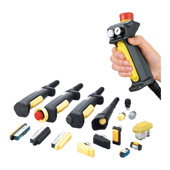
- Page 1 Enabling Switches Grip Style Enabling Switches...
- Page 2 HG2S CC Pendant HE1G/HE1G-L/HE2G Grip Style Back of the HG2S CC Pendant HE1G/HE1G-L Two HE1B Enabling HE2G Switches inside HE9Z-GSH51 Grip Style Enabling Switch HG1H/1T Small Teaching Pendant Housing + HE5B Enabling Switch...
- Page 3 Operation of enabling switches The requirement for operation of 3-position enabling switches (according to IEC 60204-1; 9.2.5.8): Position 1 When an enabling device is provided as a part of a sys tem, it shall be designed to allow motion when 1.
- Page 4 Enabling Switch and Grip Style Enabling Switch Selection Guide Enabling Switch HE1B HE2B HE3B HE5B Side Mounting Model Rectangular ø16mm Round Hole ø16mm Round Hole Top Mounting (w/ and w/o rubber boot) (w/ and w/o rubber boot) (w/ rubber boot)
- Page 5 Enabling Switch and Grip Style Enabling Switch Selection Chart Enabling Switch Selection Chart According to ISO/IEC Standards ISO 12100-2: 2003 Model Standards Marks Page Control mode for setting, teaching, HE1B-M1N process changeover, fault-finding, cleaning IEC/EN60947-5-8 or main tenance IP40 Panel Top Installation UL508 4.11.9 CSA C22.2 No.
- Page 6 Enabling Switch and Grip Style Enabling Switch Selection Chart Enabling Switch Selection Chart According to ISO/IEC Standards Model Standards Marks Page ISO 12100-2: 2003 HE9Z-GSH51 Monitor Switch Size Control mode for Additional (HE9Z-GSH51) +HE5B-2P* for Position setting, teaching, Switch EN60529 Detection process changeover, UL50...
-
Page 7: Specifications
Mounting Screw Recommended Tightening HE1B-M1: M3 screw / 0.5 to 0.8 N·m Torque HE1B-M1N: M2.6 screw / 0.4 to 0.6 N·m Degree of Protection IP40, except terminals (IEC 60529) Conditional Short-circuit Current 50A (250V) (Use 250V/10A fast-blow fuse for short-circuit protection.) Direct Opening Force 30N minimum (position 2 →... -
Page 8: Operation Characteristics
HE1B Basic Three-position Enabling Switches Operation Characteristics Position 1 Position 2 Position 3 Approx. 15N Operating Force (reference value) (when pressing the center) Approx. 3N : ON (closed) Travel (mm) : OFF (open) ±0.3 ±0.3 ±0.5 Pressing (position 1 to 2 to 3) - Page 9 HE2B HE2B Double Three-position Enabling Switches Multi-contact 3-position enabling switches Ideal for installing in large teach pendants • Ergonomically-designed OFF-ON-OFF operation. • Easy recognition of position 1 to 2 transition is made possible by a snap action switch. • Sufficient difference in operating force is provided for shifting from posi t ion 2 to 3. • Low pressure is required to maintain position 2, allowing for longtime operation. • Reliable operation is assured even when the edge of the operator button is pressed. • The switch does not turn ON while being released from position 3 (OFF) to position 1 (OFF) (IEC60204-1, 9.2.5.8). • Some teach pendants are equipped with two 3-position enabling switches, and when one switch is pressed to position 3 (OFF), the other switch must not enable machine operation even when pressed to posi t ion 2. Enabling of machine operation must resume after both switches are released. For this purpose, also available are 3-position enabling switches with monitoring switches for button returned to position 1 and button pressed to position 3 (monitor switches have direct opening action mechanism). • Two contacts are provided in a 3-position enabling switch so that even if one contact fails due to welding or short-circuit, the other (some models only)
- Page 10 (position 3 to 1) 11-12 21-22 31-32 41-42 Notes: • When a rubber boot is used, the operating force depends on the operating temperature. • The operating force to shift the switch from position 2 to position 3 can be changed. For details, contact IDEC.
- Page 11 HE2B HE2B Double Three-position Enabling Switches Terminal Arrangement (Bottom View) IDEC Logo Side IDEC Logo Side IDEC Logo Side HE2B-M200 HE2B-M211 HE2B-M222 • 3-position switch (note): 2 contacts, terminal nos. between NO1 – C1, NO2 – C2 • Button return monitor switch: 0 to 2 contacts, terminal nos. between 11 – 12, 21 – 22 • Button depress monitor switch:...
- Page 12 HE3B ø16mm Rectangular Three-position Enabling Switches Rectangular operator part with ø16 mm mounting for easy installation. 2-contact 3-position enabling switches ideal for installing in small teach pendants. • Ergonomically-designed OFF-ON-OFF operation. • Easy recognition of position 1 to 2 transition is made possible by a snap action switch.
- Page 13 Notes: • When rubber boot is used, operating force depends on the operating temperature. • The operating force to shift the switch from position 2 to position 3 can be changed. For details, contact IDEC. Terminal Arrangement (Bottom View) Mounting Hole Layout • 3-position switch (Note)
- Page 14 HE5B ø16mm Round Three-position Enabling Switches Round-shaped operator for ø16 mm mounting hole. 3-position enabling switch with two contacts, ideal for installing in small teaching pendants. • Ergonomically-designed OFF-ON-OFF operation. • Easy recognition of position 1 to 2 transition is made possible by a snap action switch.
-
Page 15: Operating Characteristics
(position 3 to 1) Notes: • Operating force depends on ambient temperature. • The operating force to shift the switch from position 2 to position 3 can be changed. For details, consult IDEC. Terminal Arrangement (Bottom View) Mounting Hole Layout • 3-position switch (Note) • Recommended Tightening Torque... - Page 16 HE5B ø16mm Round Three-position Enabling Switches Grip Style Enabling Switch Housing HE5B enabling switches can be installed in the HE9Z-GSH51 grip style enabling switch housing to be used as 3-position grip style enabling switches. Part No. Ordering No. Package Quantity HE9Z-GSH51 HE9Z-GSH51 Specifications...
- Page 17 Note 1: Silicon rubber: Can be used in general factories. Remaining flexible in cold tempera- tures. Suitable for applications in a wide operating temperature range. (20 and 02 are not standard. Contact IDEC for details.) Note 2: NBR/PVC polyblend: Oil-proof. Suitable for environments subjected to machine oil and for painting robots where silicon rubber cannot be used.
- Page 18 • When a rubber boot is used, the operating force depends on the operating temperature. • The operating force to move the button from position 2 to position 3 can be changed. For details, contact IDEC. 29.4 ±0.2 Terminal Arrangement (bottom view) 37.4...
- Page 19 • Emergency stop switch and momentary pushbutton versions are available. • Cable gland supplied. • HE1G-21SM is IP66 waterproof. • Can be used for applications required by the ANSI robot stan- dard. (HE1B embedded) HE1G Contact Configuration Package Rubber Boot Part No.
- Page 20 HE1G Grip Style Three-position Enabling Switches Specifications IEC60947-5-1, EN60947-5-1 (TÜV approved), Applicable Standards JIS C8201-5-1, EN60947-5-8 (TÜV approved) GS-ET-22 (TÜV approved), UL508 (UL listed), CSA C22.2 No. 14 (c-UL listed) ISO12100-1, -2/EN12100-1, -2, IEC60204-1/EN60204-1, ISO11161/prEN11161, Applicable Standards for Use ISO10218/EN775, ANSI/RIA R15.06, ANSI B11.19 Silicon rubber boot: –25 to 60°C (no freezing) Operating Temperature...
- Page 21 HE1G HE1G Grip Style Three-position Enabling Switches Dimensions HE1G-21SM HE1G-20ME HE1G-20MB / HE1G-21SMB Emergency Stop Switch Momentary Pushbutton Cable Gland (supplied with grip style enabling Cable Gland (supplied with grip style enabling Cable Gland (supplied with grip style enabling switch) switch) switch) Part No.: SKINTOP BS-M20 ×...
- Page 22 HE1G-L Grip Style Three-position Enabling Switches The distinctive tactile feedback makes it easy to know the current position of the switch. Light operating force ideal for long-hour operation • Ergonomically-designed OFF-ON-OFF operation. • The switch does not turn ON when being released from position 3 (OFF when pressed) to position 1 (OFF when released) (IEC 60204- 1, 9.2.5.8).
- Page 23 HE1G-L HE1G-L Grip Style Three-position Enabling Switches Specifications Operating Characteristics IEC60947-5-1, EN60947-5-1 (TÜV approval) HE1G-L21SM, HE1G-L21SMC, JIS C8201-5-1, EN60947-5-8 (TÜV approval) GS-ET-22 (TÜV approval) HE1G-L21SM-1N, HE1G-L21SMC-1N Applicable UL508 (UL listed) (screw terminal only) Standards CSA C22.2 No. 14 (c-UL listed) Position 1 Position 2 Position 3...
- Page 24 • The operating force required to shift from position 1 (contact OFF) to position 2 (contact ON) is reduced by 50% com- HG9Z-PS1 pared with IDEC’s HE1G grip style enabling switch. Less Handstrap (optional) operating force ensures worry-free operation. • Tactile clicking feedback allows easy recognition of switch operation when shifting from position 1 (contact OFF) to position 2 (contact ON).
- Page 25 HE2G HE2G Grip Style Three-position Enabling Switches Contact Ratings Specifications 250V (momentary IEC60947-5-1 pushbutton and key EN60947-5-1 (TÜV approval) Rated Insulation Voltage (Ui) selector: 125V) / JIS C8201-5-1 30V (with pilot light) EN60947-5-8(TÜV approval) Applicable Standards GS-ET-22(TÜV approval) 3A (emergency stop Rated Thermal Current (lth) UL508 (UL recognized) switch: 5A)*...
- Page 26 HE2G Grip Style Three-position Enabling Switches Operation Characteristics Contact Arrangement (Internal Connector) Position 1 Position 2 Position 3 Internal Connector Pin No. Terminal No. Internal Connector/ Solder Terminal 4-pin 6-pin Pressing NO1—C1/A1-B1 (Position 1 2 3) 31—32/A2-B2 NO2—C2/A3-B3 Releasing NO1—C1/A1-B1 (Position 2 1) 31—32/A2-B2 NO2—C2/A3-B3...
-
Page 27: Safety Precautions
Rubber boot embedded inap propriate direction, otherwise the waterproof function can be dam aged. Wiring Instructions HE1B/HE2B/HE3B/HE5B/HE6B Enabling Switch Reinforcing Rib • Applicable wire size: 0.5 mm maximum × 1 pc. • Solder the terminal at a temperature of 310 to 350°C within 3 sec onds using a soldering iron. - Page 28 Three-position Enabling Switches/Grip Style Three-position Enabling Switches HE1G/HE1G-L Grip Style Enabling Switch Recommended Tightening Torque Wire Length inside the Grip Style Enabling Switch Parts for Tightening Torque Terminal No. 1–4 Terminal No. 5–8 A Base and rubber kit (M4 screw × 3) 1.1 to 1.3 N·m Wire length L1, L2 (mm) L1 = 40 mm...
- Page 29 When using another cable gland, always press the center of the button. refer to the tightening torque of the cable gland used. HE1B/HE2B/HE3B/HE5B/HE6B/HE1G/HE1G-L/HE2G For replacing HE2B enabling switch or rubber boot only • 3-position enabling switches output ON signals in position 2.
- Page 30 Actuator with Plastic Holder HS5 series interlock switches detect the installation/removal of grip style enabling switches. • The actuator with plastic holder for the HS5 series inter- lock switches can be installed onto the HE1G/HE1G-L/ HE2G grip style enabling switches easily using the two mounting screws supplied with the actuator.
- Page 31 HE9Z Actuator with Plastic Holder Instructions • Do not install the grip style enabling switch and the interlock switch in an area subjected to vibration. Excessive vibration may cause malfunction of the switch contacts of the grip style Mounting enabling switch. Also, exposure to vibration for a long period of The HE9Z-GP15 and the HE1G/HE1G-L are installed as shown ➀...
- Page 32 Hong Kong IDEC Izumi (H.K.) Co., Ltd. Tel: +852-2803-8989 info@hk.idec.com Germany IDEC Electrotechnik GmbH Tel: +49-40-25 30 54 - 0 service@eu.idec.com China/Shanghai IDEC (Shanghai) Corporation Tel: +86-21-6135-1515 idec@cn.idec.com Singapore IDEC Izumi Asia Pte. Ltd. Tel: +65-6746-1155 info@sg.idec.com China/Shenzhen IDEC (Shenzhen) Corporation Tel: +86-755-8356-2977 idec@cn.idec.com Thailand IDEC Asia (Thailand) Co., Ltd Tel: +66-2-392-9765...
Need help?
Do you have a question about the HE1B and is the answer not in the manual?
Questions and answers