IDEC HS5E Series Manual
Miniature solenoid locking switches
Hide thumbs
Also See for HS5E Series:
- Instruction sheet (7 pages) ,
- Manual (19 pages) ,
- Manual (16 pages)
Table of Contents
Advertisement
Quick Links
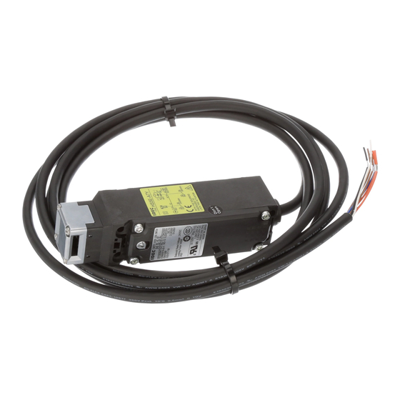
HS5E Series Miniature Solenoid Locking Switches
HS5E features:
• World's smallest 4 contact solenoid interlock switch. (35 x 40 x 146 mm)
• Four contacts
• Gold-plated contacts
• Spring lock type (unlocks when the solenoid is energized) and solenoid lock type (locks
when solenoid is energized) are available
• Flexible installation - the head can rotate, allowing 8 different actuator entries
• Metal actuator entry slot ensures long life
• Actuator locking strength is 1000N minimum (GS-ET-19)
• Integral molded cable reduces wiring time
• LED pilot light indicates the solenoid status
• RoHS Directive Compliant
• Contacts are IP67 (IEC60529)
• NC contacts are direct opening (IEC/EN60947-5-1)
• Only proprietary actuators can be used, preventing unauthorized access (ISO14119,
EN1088)
• Double insulation structure - no grounding required
Spring Lock Type
• Automatically locks the actuator without power to the solenoid
• After the machine stops, unlocking is accomplished by energizing the solenoid, provid-
ing a high level of safety
• Manual unlocking is possible in the event of power failure or maintenance
Solenoid Lock Type
• The actuator is locked when energized
• The actuator is unlocked when de-
energized
Integrated Cable
Adjustable Actuator
(mainly for hinged doors)
Buy: www.ValinOnline.com | Phone 844-385-3099 | Email: CustomerService@valin.com
EN1088
EN60947-5-1
IEC60947-5-1
2 Actuator Entry Slots
Right-angle
Actuator
Green LED Indicator
Metallic Head
L-shapted Actuator
(mainly for hinged
doors)
GS-ET-15
BG standard
in Germany
Direct Opening
Action
Straight Actuator
(mainly for sliding
doors
Manual Unlocking
Actuator Slot
Double
Insulation
Advertisement
Table of Contents

Subscribe to Our Youtube Channel
Related Manuals for IDEC HS5E Series


Summary of Contents for IDEC HS5E Series
- Page 1 HS5E Series Miniature Solenoid Locking Switches HS5E features: • World’s smallest 4 contact solenoid interlock switch. (35 x 40 x 146 mm) • Four contacts • Gold-plated contacts • Spring lock type (unlocks when the solenoid is energized) and solenoid lock type (locks when solenoid is energized) are available •...
-
Page 2: Part Numbers
Part Numbers Body Lock gement Pilot Light Cable Length Part Number Circuit Number Contact Arra Mechanism Main Circuit: 1NC+1NC, Monitor Circuit: 1NO, 1NO HS5E-A4001 Without HS5E-A4003 (–) HS5E-A4005 Main Circuit: HS5E-A4401-G Monitor Circuit: With HS5E-A4403-G Monitor Circuit: HS5E-A4405-G Main Circuit: 1NC+1NC, Monitor Circuit: 1NO, 1NC HS5E-B4001 Without HS5E-B4003... -
Page 3: Circuit Diagrams
Circuit Diagrams Unlocking Using Status 1 Status 2 Status 3 Status 4 Manual Unlock Key Door closed Door opened Door open Door open Door closed • • • • • Machine ready to Machine cannot be Machine cannot be Machine cannot be Machine cannot be •... -
Page 4: Specifications
Specifications Part Number Key ISO14119, IEC60947-5-1, EN60947-5-1 (TÜV approval), EN1088, GS-ET-19 Conforming Standards (BG approval), UL508 (UL recognized), CSA C22.2, No. 14 (c-UL recognized) HS5E - 4 4 01 - G Application Standards IEC60204-1/EN60204-1 Operating Temperature –25 to 50°C (no freezing) Relative Humidity 45 to 85% (no condensation) Pilot Light Color... - Page 5 Dimensions (mm) and Mounting Hole Layouts Actuator Keys HS5E-**4*G (w/pilot light) Horizontal Mounting/Straight Actuator (HS9Z-A51) 26.4 42.2 32.9 26.4 32.9 13.4 13.4 Actuator Actuator 36.2 36.2 (6.3) Actuator Stop Actuator Stop 145.7 (6.3) 145.7 4-M4 Screws 20 to 22 6 ±1 Slot Plug (Note) Mounting Hole Layout...
- Page 6 Dimensions and Mounting Hole Layouts, continued Vertically/Horizontally Movable Actuator (HS9Z-A55) Actuator Orientation Angle Adjustment Horizontal Swing 3 (M3 Hexagon Socket Head Screw) The orientation of the actuator operation (horizontal/vertical) can be changed with the Orienting Actuator Stop orientation part (white plastic part) installed on the back of the actuator. Insert (Note) Do not loose the orientation part, otherwise the actuator will not operate properly.
-
Page 7: Mounting Examples
Operating Instructions Minimum Radius of Hinged Door Actuator Angle Adjustment • When using the safety switch for a hinged door, refer to the minimum radius • Using the angle adjustment screw, the actuator angle can be adjusted (refer of doors as shown below. For doors with small minimum radius, use adjust- to the dimensional drawing). -
Page 8: Wire Identification
Instructions, continued For Manual Unlocking Cables • Do not fasten or loosen the gland at the bot- • Spring lock type tom of the safety switch. The HS5E allows manual unlocking of the actuator to pre-check proper door operation before wiring or turning power on, as well as for an emergency or a •... -
Page 9: Safety Precautions
Safety Precautions • In order to avoid electric shock or a fire, turn the power off before installation, • Do not place a PLC in the circuit between the safety switch and the load. The removal, wire connection, maintenance, or inspection of the switch. safety security can be endangered in the event of a malfunction of the PLC. -
Page 10: Wire Connection
HS1E Precautions Wire Connection 1. This unlocking method is intended for an escape from a machine when a person is locked in. For access to the unlocking entry, an access hole should be opened on the mounting panel. When opening the hole, apply proper protection against water or other •... -
Page 11: Operation Precautions
Operation Precautions Applicable Crimping Terminals Applicable Connectors (As shown below) • (Refer to the Crimping Terminal 1 or 2 shown in the drawing below.) • Use connectors which maintain the IP67 protection. • HS1C • Applicable Connector Dimensions Terminals No. 1 to 6: Use solid or stranded wires only (crimping terminals •... - Page 12 Actuator Angle Adjustment • After installing the actuator, open the door. Then adjust the actuator so that its edge can be inserted properly into the entry slot of the safety switch. • Using the screw (M3 hex socket head screw), the actuator angle can be adjusted (refer to the dimensional drawing).
Need help?
Do you have a question about the HS5E Series and is the answer not in the manual?
Questions and answers