Table of Contents
Advertisement
Quick Links
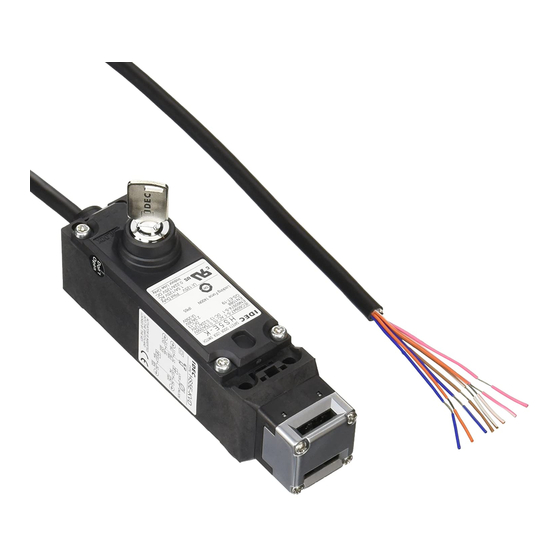
HS5E-K Interlock Switches with Key
New interlock switches that can be locked and unlocked with a key.
• Head removal detection circuitry .
• High-security pin tumbler key is used . Sixteen types of key
numbers are available .
• Available with rear unlocking button for emergency escape .
• Accessory available for aluminum frame mounting .
• Gold-plated contacts .
• The locking strength is 1400N minimum . (GS-ET-19)
• The head orientation can be rotated, allowing 8 different
actuator entries .
• Metal actuator entry slot ensures high durability .
• Actuator with rubber bushings alleviates the impact of
the actuator entry slot .
• Environmentally-friendly . RoHs directive compliant .
• Double insulation structure . No need for grounding .
• Compact body: 35 × 40 × 146 mm
Ratings
Contact Rating
Rated Insulation Voltage (Ui) (Note 1)
Rated Thermal Current (Ith)
Rated Voltage (Ue)
Resistive Load (AC-12)
Rated
AC
Inductive Load (AC-15)
Current
(Ie)
Resistive Load (DC-12)
DC
(Note 2)
Inductive Load (DC-15)
Minimum applicable load (reference value) = 3V AC/DC, 5 mA
(Applicable range may vary with operating conditions and load types .)
Note 1: UL rating:
125V
Note 2: TÜV rating:
AC-15, 0 .5A/250V, DC-13, 0 .22A/125V
UL, c-UL rating: Pilot Duty AC 0 .5A/125V,
Pilot Duty DC 0 .22A/125V
Key Specifications
Operating Method
2-position maintained
Mechanical Durability
100,000 operations minimum
Insertion/Removal Durability
10,000 operations minimum
Operator Strength
1 .0 N·m minimum
Direct Opening Force
0 .6 N·m minimum
Direct Opening Angle
60° minimum
Part No. Development
H S 5 E - K V A 0 L 0 3 - 2 A 5 0 1
Circuit Code
Main
Door Monitor
Lock Monitor
Circuit
Circuit
Circuit
VA:
1NC, 1NO
1NC, 1NO
—
VD:
2NC
2NC
—
Pilot Light
0: None
Rear Unlocking Button
L: With
Blank: Without
Cable Length
03: 3m
05: 5m
250V
Operating temperature:
–25°C to 60°C: 2 .5A max .
60°C to 65°C: 1 .5A max .
65°C to 70°C: 1 .0A max .
30V
125V
250V
−
2A
1A
−
1A
0 .5A
2A
0 .4A
0 .2A
1A
0 .22A
0 .1A
Key number
Blank: Standard Key
number (500)
or
501 to 515
Key removal specifications
A: Removable in
all positions
B: Removable at UNLOCK
C: Removable at LOCK
Operator position
2: 2-position
Right-angle Actuator
(SUS304)
Angle Adjustable
Actuator (vertical)
Right-angle Actuator
w/rubber bushings
General Specifications
ISO14119, IEC60947-5-1,
EN60947-5-1 (TÜV approval), EN1088,
GS-ET-19 (TÜV approval),
UL508 (UL recognition),
Applicable Standards
CSA C22 .2 No . 14 (c-UL recognized)
IEC60204-1/EN60204-1
(applicable standards for use)
Operating
-25 to +70°C (No freezing)
Temperature
Relative Humidity
45 to 85% (No condensation)
Storage Temperature
-40 to +80°C (No freezing)
Pollution Degree
3
Impulse Withstand
2 .5 kV
Voltage
Between live and dead metal parts: 100 MΩ
minimum (500V DC megger)
Between live metal part and ground:
Insulation Resistance
100 MΩ minimum (500V DC megger)
(500V DC megger)
Between live metal parts:
100 MΩ minimum (500V DC megger)
Between terminals of the same pole:
100 MΩ minimum
Electric Shock Class
Class II (IEC61140)
Degree of Protection
IP65 (IEC60529)
Operating extremes: 100 m/s
Shock Resistance
Damage limits:
Operating extremes:
Vibration Resistance
10 to 55 Hz, amplitude 0 .35 mm
Damage limits: 30 Hz, amplitude 1 .5 mm
Actuator Operating
0 .05 to 1 .0 m/s
Speed
Actuator HS9Z-A51:
Direct Opening Travel
Actuator HS9Z-A51A/A52/A52A/A53/A55: 12 mm
minimum
Direct Opening Force
80N minimum
Actuator Retention
1,400N minimum (GS-ET-19)
Force (Note 1)
Operating Frequency
900 operations per hour
Rear Unlocking
Button Mechanical
3,000 operations minimum (HS5E-KL)
Durability
Mechanical Durability
1,000,000 operations minimum (GS-ET-19)
100,000 operations minimum (AC-12, 250V, 1A)
1,000,000 operations minimum (24V AC/DC, 100
Electrical Durability
mA)
(Operating frequency: 900 operations per hour)
Performance between
Mechanical durability: 10 operations minimum
41 and 42 when head
Insulation resistance: 100 MΩ (initial value)
is removed
Withstand voltage: 1,000V for 1 minute (initial value)
Conditional Short-
50A (250V) (Note 2)
circuit Current
UL2464, No . 22 AWG
Cable
(12-core, 0 .3 mm
Cable Diameter
ø7 .6 mm
Weight (approx .)
510g (3m cable), 680g (5m cable)
Note 1: See page 61 for actuator retention force .
Note 2: Use 250V/10A fast-blow fuse for short-circuit protection .
Straight
Actuator
2
1,000 m/s
2
11 mm minimum
2
or equivalent/core)
HS5E-K
57
Advertisement
Table of Contents

Related Manuals for IDEC HS5E-K


Summary of Contents for IDEC HS5E-K
- Page 1 HS5E-K HS5E-K Interlock Switches with Key New interlock switches that can be locked and unlocked with a key. • Head removal detection circuitry . • High-security pin tumbler key is used . Sixteen types of key Straight numbers are available .
- Page 2 Head Removal Detection Circuitry (patented) Head removal detection circuitry is employed in the HS5E-K . With this innovative function, the monitor circuit (41-42) turns off when the head is removed from the switch, such as when removing the head to change the head direction (applicable with all models of HS5E-K) .
-
Page 3: Interlock Switch
HS5E-K HS5E-K Interlock Switches with Key Interlock Switch Package Quantity: 1 Rear Unlocking Circuit Cable Contact Configuration Key Removal Position Part No . Button Code Length HS5E-KVA003-2A A (removable in all positions) HS5E-KVA005-2A HS5E-KVA003-2B LOCK UNLOCK B (removal in UNLOCK... - Page 4 HS5E-K Interlock Switches with Key Dimensions and Mounting Layouts All dimensions in mm . HS5E-K When using Horizontal Mounting / Straight Actuator (HS9Z-A51) 26.4 26.4 42.2 73.2 73.2 Actuator 36.2 Actuator 36.2 Actuator Stop (6.3) Actuator Stop (6.3) 145.7 145.7...
- Page 5 When a retention force of 500N or more is required, use HS9Z-A53 . • For actuator dimensions, see page 62 . • See “Minimum Radius of Hinged Door” on page 66 and 67 when using the HS5E-K on hinged doors . Accessories Package Quantity: 1 Description Part No .
- Page 6 HS5E-K Interlock Switches with Key Actuator Dimensions and Mounting Hole Layouts All dimensions in mm . Straight Actuator (HS9Z-A51) Right-angle Actuator (HS9Z-A52) 32.4 Actuator Mounting Hole Layout (Straight, Right-angle) (Note) Actuator Stop Actuator Stop (supplied with the actuator) (Note) (supplied with the actuator)
-
Page 7: Accessory Dimensions
HS5E-K HS5E-K Interlock Switches with Key Accessory Dimensions All dimensions in mm . Door Handle Actuator HS9Z-DH5RH (for right-hand door) / Actuator with Key HS5E-K Interlock Switch Stainless Rear Handle (diecast aluminum) Diecast Aluminum Steel (yellow) (plated) Legend Description Rear Unlocking Handle Unit for Right-hand Door (HS9Z-DH5RH) ➀... - Page 8 HS5E-K Interlock Switches with Key Sliding Actuator (HS9Z-SH5) Plug Actuator (HS9Z-A5P) 26.5 Rivet: Stainless Steel 37.5 Spacer: Steel 26.5 37.5 Handle: Aluminum A部 Thickness: 2 A部 B部 36.2 A部 A部 B部 36.2 (40) HS5E形 Actuator: stainless steel HS5B形 (40) 安全スイッチ...
- Page 9 HS5E-K HS5E-K Interlock Switches with Key Circuit Diagrams and Operating Characteristics Status 1 Status 2 Status 3 Rear Manual Unlock • Door closed • Door closed • Door opened • Door closed Interlock Switch Status • Machine ready to • Machine cannot be • Machine cannot be • Machine cannot be...
-
Page 10: Safety Precautions
HS5E-K Interlock Switches with Key Safety Precautions • In order to avoid electric shock or fire, turn the power off • Do not place a PLC in the circuit between the interlock before installation, removal, wire connection, maintenance, switch and the load . Safety and security can be endan- or inspection of the interlock switch . -
Page 11: Mounting Examples
Do not use plastic and metallic heads of HS5D/HS5B horizontal) Actuator interlock switches on the HS5E-K . Be sure to use HS5E metallic heads . The metal heads of the HS5E, HS5D, and • When the door hinge is on the extension line of the inter- HS5B look similar . - Page 12 • When connecting the HS5E-K to a safety circuit, connect the door monitor circuits (11-12) and the lock monitor 1 . Install a connecting rod onto the push rod on the HS5E-K circuits (41- 42) in series . (GS-ET-19) rear unlocking button interlock switch (HS5E-KL, sold •...
- Page 13 Orange Pink 12 Gray/White Mounting Screws Insulation • HS5E-K interlock switch: 1 .8 to 2 .2 N·m (four M4 screws) (Note) 9 11 • Rear unlocking button: 0 .5 to 0 .7 N·m Jacket • Rear unlocking button kit: 4 .8 to 5 .2 N·m (M5 Screw) Circuit Code Identification •...
- Page 14 Logic Circuit using FS1A Safety Controller Example 1: Hostage control (one robot) Turn the key selector switch to Teach Mode and remove the key . Unlock HS5E-K using the same key, then remove the key and open the door to enter .
- Page 15 Three FS1A safety controllers are required for two robots and four FS1A safety controllers for three robots . Turn the key selector switch of the first robot (logic no . 103) to Teach Mode and remove the key . Unlock the HS5E-K interlock switch using the same key and open the door to enter .
Need help?
Do you have a question about the HS5E-K and is the answer not in the manual?
Questions and answers