
Related Manuals for IDEC SX5E Series


Summary of Contents for IDEC SX5E Series
- Page 1 B-2003 (0) SX5E Series Entry-Level Industrial Ethernet Switch SX5Eシリーズ 取扱説明書 SX5E Series INSTRUCTION SHEET SX5E 系列 使用说明书...
- Page 3 Disclaimer: IDEC Corporation. tries to keep the content of this manual as accurate and as updated as possible. This document is not guaranteed to be error-free, and we reserve the right to amend it without notice to users. All rights reserved.
- Page 4 Use compatible connectors and cables. If you are not sure, contact our sales or technical support personnel for confirmation. Do not disassemble, repair, or modify the SX5E Series. If any part is lost, contact our sales or technical support personnel to purchase a replacement.
-
Page 5: Product Overview
1 Product Overview SX5E includes a series of entry-level industrial Ethernet switches applicable to factory automation, wind power, distribution network automation, subway PIS, power SCADA, sewage treatment, metallurgy, intelligent transportation, rail transit, and many other industries. Broadcast storm protection can be configured through DIP switch. The series switches support DIN rail mounting. -
Page 6: Structure And Interface
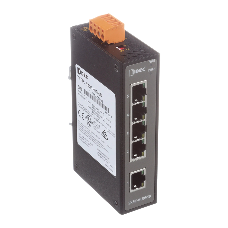
2 Structure and Interface PWR1 PWR2 PW R2 PW R1 OFF ON SX5E-HU055B Figure 1 Front Panel Figure 2 Top Panel (1) Power 1 LED (2) Power 2 LED (3) 10/100Base-T(X) Ethernet port (4) 10/100Base-T(X) Ethernet port connection status LED (green) (5) 10/100Base-T(X) Ethernet port speed LED (yellow) (6) Grounding screw (7) Power terminal block... -
Page 7: Mounting Modes And Steps
Devices are to be installed in IP54 enclosure and accessible only by the use of a tool. Use the SX5E Series in environments of pollution degree 2. (according to IEC 60664-1). Customer shall insure device working in the right ambient temperature, -40°C~+75°C (without freezing). - Page 8 3.2.1 DIN-Rail Mounting Step 1: Select the mounting position for the device and secure adequate space and heat dissipa ion. Step 2: Insert the connecting seat onto the top of the DIN rail, and push the bottom of the device inward and upward to ensure the DIN rail fits in the connecting seat.
- Page 9 3.2.2 DIN-Rail Dismounting Step 1: As shown in the following figure, press the device downward and move the device in direction 1 until the bottom of the device is detached from the DIN rail. Step 2: Pull the device upward and move the device in direction 2 until the device is removed from the DIN rail completely.
-
Page 10: Power Terminal Block
4 Connection 4.1 Grounding Grounding protects the device from lightning and interference. Therefore, you must ground the device properly. You need to ground the device before it is powered on and disconnect the grounding cable after the device is powered off. There is a grounding screw (see Figure 2) on the top panel of the switch. - Page 11 4-Pin 5.08mm-Spacing Plug-in Terminal Block Figure 6 4-Pin 5.08mm-Spacing Plug-in Terminal Block (socket) Table 2 Pin Definitions of 4-Pin 5.08mm-Spacing Plug-in Terminal Block Pin Number DC Wiring Definition AC Wiring Definition PWR1: - PWR1: N PWR1: + PWR1: L PWR2: - PWR2: N PWR2: +...
-
Page 12: Dip Switches
Caution: Provision shall be made to prevent the rated voltage from being exceeded by transient disturbances of more than 140% of the rated voltage. Power adapter provide by end customer shall be non-sparking. Before connec ing the device to power supply, make sure that the power input meets the power requirement. - Page 13 5 LEDs Table 5 LEDs State Description The power 1 is connected and operates properly. Power 1 LED The power 1 is not connected or operates abnormally. The power 2 is connected and operates properly. Power 2 LED The power 2 is not connected or operates abnormally.
- Page 14 7 Option SX9Z-PMTD04PN02 Power Supply Terminal Block (2 pieces) SX9Z-CAP2PN02 Connector cover for RJ45 port (2 pieces) SX9Z-1A01 Direct mounting bracket (1piece) Direct moun ing bracket Step 1: Unfix the DIN rail connecting seat after removing fixation screws. Step 2: See the figure as below, and fix the Direct moun ing bracket vertically with supplied two screws.
- Page 15 免責事項:IDEC 株式会社は本マニュアルの内容を可能な限り正確かつ最 新の状態に保つよう取り組みます。ただし、本書には誤りが含まれている 可能性があり、当社はユーザーへの告知なしに誤りを修正する権利を有し ます。 著作権について 本書のいかなる部分も、 書面による IDEC 株式会社の事前許可のない限り、 形式および手段を問わず、引用、複写、翻訳、注釈、および複製を禁じま す。 Copyright © 2017 IDEC Corporation 安全上のご注意 本製品を安定して動作させるためには、本注意事項を守って本製品をお使 いいただく必要があります。本装置を人為的に損傷させたり、破壊したり しないでください。人と機器の安全のために、本装置のご使用前に本注意 事項をよくお読みください。本取扱説明書は、後でご覧になれるように保 管してください。当社は、本注意事項を守らなかったことにより生じたい かなる危害および機器の損害についても、その責任を負いません。 万一本製品の故障により重大な損害の発生するおそれがある用途へご 使用の際は、 バックアップやフェールセーフ機能をシステムに追加して ください 本装置は必ず清潔で乾燥した場所でお使いください。周囲相対湿度を、 5%から 95%(結露なし)の範囲に維持してください。 高磁場、強い衝撃、および高温にさらされる環境に、本装置を置かない でください。動作および保管温度を許容範囲内に保ってください。 本装置の据え付けおよび設置は、確実にしっかりと行ってください。 本装置は清潔に保ってください。拭く必要がある場合は、柔らかい木綿...
- Page 16 むき出しの金属線は、酸化および帯電の恐れがあるため、いかなる物も 使用しないでください。 本装置の据え付けは、国および地域の関連規制に従って行ってください。 電源を入れる前に、 電源が本装置の許容範囲内であることを確認してく ださい。高電圧により本装置が損傷する恐れがあります。 電源コネクタと他のコネクタをしっかりと相互接続してください。 濡れた手で電源を抜き差ししないでください。装置の電源が入っている ときは、装置のいかなる部分にも濡れた手で触らないでください。 電源ケーブルに接続された装置を操作するときは、全ての貴金属類(指 輪、腕輪、腕時計、ネックレスなど)および他の全ての金属類を外して ください。感電、火傷、および融解の恐れがあります。 激しい雷雨のときは、装置を操作したり、ケーブルを抜き差ししたりし ないでください。 コネクタおよびケーブルは対応品をお使いください。わからない場合は、 当社の営業またはテクニカルサポート担当者に問い合わせ、確認してく ださい。 分解、修理、改造等は行わないでください。 部品紛失の際は、 当社の営業またはテクニカルサポート担当者に問い合 わせ、交換品をご購入ください。別の経路から部品を購入しないでくだ さい。 装置の廃棄は関係国の法的規定に従い、環境汚染を防止してください。 次の場合は、電源を速やかに遮断し、当社窓口にお問い合わせください。 機器内部に浸水した。 機器または筐体が損傷した。 機器の挙動または性能に異常な変化が見られる。 ...
- Page 17 1 製品概要 SX5E 形はエントリーレベルの産業用イーサネットスイッチで、ファク トリーオートメーション、 風力、 配電網自動化、 地下鉄旅客案内システム、 電力 SCADA システム、汚水処理、冶金、高度道路交通システム、鉄道輸 送、その他のさまざまな業種でお使いいただけます。 ブロードキャストストーム防止機能は、DIP スイッチにより設定できま す。 本シリーズのスイッチは、DIN レールへの取り付けに対応しています。 SX5E 形には、 10/100Base-T(X)イーサネットポートが 4 ポート備えられて います。 表 1 基本特性と仕様 形式 SX5E-HU055B 定格入力電圧 12/24/48VDC(9-60V DC) (入力電圧範囲) 24VAC(18-30V AC、50/60Hz) 定格消費電力 3.4W(最大) 端子台 4 ピン 5.08mm ピッチ差込式端子台 筐体...
- Page 18 2 構成とインターフェイス PWR1 PWR2 PW R2 PW R1 OFF ON SX5E-HU055B 図 1 正面パネル 図 2 上面パネル (1) 電源 1LED (2) 電源 2LED (3) 10/100Base-T(X)イーサネットポート (4) イーサネットポート接続状態 LED(緑) (5) イーサネットポート速度 LED(黄) (6) 接地ネジ (7) 電源コネクタ (8) DIP スイッチ 注意: RJ45 コネクタカバー(オプション品)を購入してポートを清潔に 保ち、スイッチ性能を確保することを推奨いたします。...
- Page 19 3 取り付け 3.1 寸法図 68.0 29.6 25 0 図 3 SX5E 外形寸法図(DIN レール取付時 単位 mm) 注意: 放熱のため、本スイッチの筐体は動作中に熱くなります。触れ るときは注意を払い、また、動作中は本スイッチの筐体を覆わ ないでください。 本マニュアルの各図は参考までにご覧ください。 3.2 取り付け方法と手順 本装置は DIN レールによる取り付けに対応しています。設置前に、下記 要件が満足されているか確認してください。 注記: 装置は IP54 エンクロージャ内に設置し、 道具を使用しなければ 触れないようにする。 本製品は汚損度 2 の環境下で使用してください。 (IEC60664-1 規格に基づく) ...
- Page 20 3.2.1 DIN レールに取り付ける 手順 1: 装置の取り付け位置を決め、十分な空間と放熱を確保します。 手順 2: DIN レール取付金具を DIN レール上部に挿入し、装置底部を内側に 押し上げて DIN レールを DIN レール取付金具にはめ込みます。 この時、下図のように DIN レール取付金具内部のバネ金具が正しく DIN レールにかかり、装置がしっかりと DIN レールに取り付けられ ていることを確認します。 DINレール取付金具 DINレール DINレール取付金具 DINレール取付金具 ばね金具 ばね金具 DINレール DINレール 図 4 DIN レールへの取り付け...
- Page 21 3.2.2 DIN レールから取り外す 手順 1: 下図のように、装置を押し下げ、1 の方向に動かして装置の底部を DIN レールから取り外します。 手順 2: 装置を引き上げて 2 の方向に動かし、装置を DIN レールから完全に 取り外します。 DIN取付金具 DINレール 図 5 DIN レールからの取り外し...
- Page 22 4 接続 4.1 接地 接地により装置を雷および干渉から保護できます。そのため、装置を適 切に接地する必要があります。 装置を接地してから電源を入れてください。 また、接地ケーブルを取り外す前に装置の電源を切ってください。 接地ねじが本スイッチの上面パネルにあります(Figure 2 参照) 。このね じは筐体を接地するためのものです。接地ケーブルの一端をコールドプレ ス端子にクリンプし、その接地ケーブル端を接地ねじに固定してもう一方 のケーブル端をしっかりと接地します。 注記: 筐体接地ケーブルの横断面積>2.5mm 、接地抵抗<5。 4.2 電源端子 電源端子台が装置の上面パネル上にあります。電源線を本端子台に接続 し、装置に電源を供給する必要があります。本スイッチは電源の冗長化に 対応しており、 4 ピン 5.08mm ピッチの差込式端子台が備えられています。 一方の電源が故障した場合でも本スイッチは正常に動作を続けられるので、 ネットワークの信頼性が向上します。 注記: 電源入力端子には、 必ず周囲温度 80℃での使用に適合する導体 を使用してください。 電源端子台への接続を意図する全てのフィールド配線は、必ず 絶縁を局部的に除去した銅導体により構成してください。中間 接続部品は、フェルールを除いて、いかなる部品も追加しない でください。...
- Page 23 4 ピン 5.08mm ピッチ差込式端子台 図 6 4 ピン 5.08mm ピッチ差込式端子台(ソケット) 表 2 4 ピン 5.08mm ピッチ差込式端子台のピン割当 ピン番号 DC 配線割当 AC 配線割当 電源 1:- 電源 1:N 電源 1:+ 電源 1:L 電源 2:- 電源 2:N 電源 2:+ 電源 2:L 配線と取り付け 手順...
- Page 24 注意: 一時的な乱れによる定格電圧の 140%を超える電圧上昇を防止 するための対策を必ず施してください。 使用者が用意する電源アダプターは、必ず無発火性のものを ご用意ください。 装置を電源に接続する前に、電源入力が所定の電源要件を満た すことを確認してください。不適切な電源入力に接続すると、 装置が損傷する恐れがあります。 各 UL 規格に適合させるには、本機器への電源供給は Class 2 の電源から行う必要があります。 警告: いかなるものであっても、電圧警告表示のあるむき出しの導 線、端子、および部品には触らないでください。危害に至る恐 れがあります。 いかなる部品の取り外し、およびいかなるコネクタの抜き差し も、装置電源が入っているときは行わないでください。 4.3 DIP スイッチ 2 個の DIP スイッチが装置の上面パネルにあります。各スイッチの状態 には ON と OFF があり、初期状態は OFF です。各 DIP スイッチの機能を 下表に示します。...
- Page 25 5 各種 LED 表 5 各種 LED 状態 説明 電源 1 が接続され正常動作 電源 1 LED 電源 1 が未接続または動作異常 電源 2 が接続され正常動作 電源 2 LED 電源 2 が未接続または動作異常 100M 動作状態(100Base-TX) 10/100Base-T(X) イ ー サ ネ ッ トポート速度 LED(黄) 10M 動作状態または未接続 ポート接続有効 10/100Base-T(X) イ...
- Page 26 7 オプション 電源端子台コネクタ(2 個入り) SX9Z-PMTD04PN02 RJ45 コネクタカバー(2 個入り) SX9Z-CAP2PN02 直付け金具(1 個入り) SX9Z-1A01 直付け金具の取り付け 手順 1: DIN レール取付金具を固定しているネジを外し、DIN レール取付金 具を外します。 手順 2: 直付け金具を図の向きで付属のネジを使用して 2 箇所固定します。 (締め付けトルク:0.39-0.41Nm) DINレール取付金具 直付け金具 図 8 直付け金具...
- Page 27 免责声明:和泉电气(北京)有限公司竭力使本手册中的信息尽 可能准确,最新。 然而本公司不能保证本手册完全没有任何技术错误 或笔误,并保留在未通知用户的情况下对其修改的权利。 保留所有权限: 本手册著作权属和泉电气 (北京) 有限公司所有。 未经著作权人书面许可, 任何单位或个人不得以任何方式摘录, 翻版, 复制,翻译或者用于商业目的分发等行为。 侵权必究。 Copyright © 2017 IDEC CORPORATION 安全使用须知 本产品在设计使用范围内具有良好可靠的性能, 但需要避免人为 对设备造成的损害或破坏。使用设备前,请仔细阅读该手册,以保障 用户人身和设备的安全。阅读后请妥善保管本手册,以备将来参考。 对于违反安全使用须知造成的人身伤害或设备损坏, 我司不承担任何 责任。 在可能因本产品故障而导致重大故障或损害的用途中使用本产品时, 请在系统中做好备份或故障保护功能。 请勿将设备放置、安装在接近水源或潮湿的地方,保持设备周边的相 对湿度在 5%~95%范围内且无凝结。 请勿将设备放置, 安装在高磁、 强震或高温的地方, 保持设备的工作, 存储温度在规定范围内。 保持设备放置稳妥,防止坠落;保持设备安装紧固,防止滑脱。...
- Page 28 请使用我司市场人员或技术支持人员认可的连接器和线缆, 避免由于 连接器和线缆不符合规范而影响模块功能。 请勿擅自分解,修理或改装 SX5E 型。 设备零件遗失时, 请在我司市场人员或技术支持人员的指导下购买替 代零件,严禁私自选配。 需按照国家相关规定报废设备,减少对环境的污染。 在下列情况下,请立即断开电源,并与我司取得联系。 设备进水。 设备摔坏或机壳破裂。 设备工作异常或性能改变。 设备产生异味、烟雾或异常噪音。...
- Page 29 1 产品概述 SX5E 是我司面向工厂自动化,风电,配网自动化,地铁 PIS, 电力 SCADA,污水处理,冶金,智能交通,轨道交通等行业开发的 入门级工业以太网交换机, 支持常温和宽温型号选择。在可能因本产 品故障而导致重大故障或损害的用途中使用本产品时, 请在系统中做 好备份或故障保护功能。 通过设置拨码开关可实现广播风暴保护功能。 该 系 列 设 备 支 持 DIN 导 轨 式 安 装 。 SX5E 可 配 置 4 个 10/100Base-T(X)以太网接口,具体配置如下表所示。 表 1 基本性能与规格 产品型号 SX5E-HU055B 额定动作电压 12/24/48VDC (9-60VDC) 24VAC (18-30VAC,50/60Hz) (电压波动范围)
- Page 30 2 结构与接口 PWR1 PWR2 PW R2 PW R1 OFF ON SX5E-HU055B 图 1 前面板标注图 图 2 上盖板标注图安装 (1) 电源 1 指示灯 (2) 电源 2 指示灯 (3) 10/100Base-T(X)以太网接口 (4) 10/100Base-T(X)以太网接口连接状态指示灯(绿灯) (5) 10/100Base-T(X)以太网接口速率指示灯(黄灯) (6) 接地螺钉 (7) 电源端子 (8) 拨码开关 注意: 为保持接口清洁,保障设备运行性能,建议用户根据设备接口形式, 另行订购 RJ45 接口盖(附件) 。...
- Page 31 3 安装 3.1 尺寸图 68.0 29.6 25 0 图 3 SX5E 型 DIN 导轨尺寸图(单位:mm) 注意: 设备机壳是整机散热系统的一部分,正常工作时机壳会发热,设备 工作时请勿覆盖机壳。 本手册中的图片均为示意图,具体请以实物为准。 3.2 安装方式与步骤 本设备为 DIN 导轨安装。安装设备前,请确认如下安装要求: 1) 环境要求:工作温度-40°C~+75°C(无结冰) ,相对湿度 5%~95% (无凝露) ,污染等级≤ 2(满足 IEC 60664-1) 。 2) 电源要求:确认工作电压与设备上所标识的电压范围相符。 3) 接地电阻要求:<5。 4) 避免阳光直射,远离发热源或有强烈电磁干扰区域。 5) 安装环境满足 IP54 要求,不可用手直接触摸设备,避免造成人身 伤害。...
- Page 32 3.2.1 DIN 导轨安装 第 1 步,选定设备的安装位置,确保安装空间足够且散热通畅。 第 2 步,将 DIN 导轨卡扣的上部卡在 DIN 导轨上(如下图所示,确认弹 簧正确安装在 DIN 导轨上)后,向上轻推设备的下端,按箭头 2 指向转动设 备,至设备可靠的安装到 DIN 导轨上完成安装。 DIN导轨卡扣 DIN导轨 DIN导轨卡扣 DIN导轨卡扣 弹簧 弹簧 DIN导轨 DIN导轨 正确安装方法 错误安装方法 图 4 DIN 导轨安装图...
- Page 33 3.2.2 DIN 导轨拆卸 第 1 步,向下压设备并按下图箭头 1 方向转动设备,至设备下端脱离 DIN 导轨。 第 2 步,向上抬设备并按下图箭头 2 方向转动设备,至设备脱离 DIN 导 轨完成拆卸。 DIN导轨卡扣 DIN导轨 图 5 DIN 导轨拆卸图...
- Page 34 4 接线 4.1 接地 设备正常接地是设备防雷,防干扰的重要保障,所以用户必须正确连接 地线。并且在上电前接地,断电后再断开接地线。 设备上盖板有一个接地螺钉(见图 2) ,即机壳接地线处, 称“机壳地” 。 将接地线的一端与冷压端子压接后用接地螺钉固定在“机壳地”处,接地线 的另一端可靠地接入大地。 说明: 接地线截面积 2.5mm 以上;接地电阻要求:<5。 4.2 电源端子 电源端子位于设备上盖板,通过电源端子连接电源线为设备供电。本系 列设备支持冗余电源输入,采用 4 芯 5.08mm 间距插拔式接线端子,当其中 任何一路电源出现故障时,设备可以不间断正常运行,提高了网络运行的可 靠性。 说明: 现场接线使用的导体环境温度应满足 80°C。 4 芯 5.08mm 间距插拔式接线端子 图 6 4 芯 5.08mm 间距插拔式接线端子(插座)...
- Page 35 表 2 4 芯 5.08mm 间距插拔式接线端子定义 端子号 直流接线定义 交流接线定义 PWR1: - PWR1: N PWR1: + PWR1: L PWR2: - PWR2: N PWR2: + PWR2: L 接线与安装 第 1 步,按照 4.1 步骤将设备良好接地。 第 2 步,从设备上取下电源端子插头。 第 3 步, 将电源线的一端按表 2 要求插到电源端子插头里并固定电源线。 第...
- Page 36 4.3 拨码开关 设备上盖板有两个拨码开关,每个拨码开关有 ON,OFF 两种状态,默 认配置均为 OFF 状态。拨码开关Ⅰ可以实现广播风暴保护功能。 图 7 拨码开关 表 4 拨码开关功能描述 拨码开关 状态 功能描述 使能广播风暴保护功能 Ⅰ 禁止广播风暴保护功能 Ⅱ 保留 5 LED 指示灯状态 表 5 指示灯描述 状态 描述 亮 输入电源 1 连接并运行正常 电源 1 指示灯 灭 输入电源 1 未连接或运行不正常 亮...
- Page 37 6 认证 FCC 47CFR Part2 and part15 Class A 安全 UL508, Class1 Div2, CSA C22.2 No.142 7 附件(另售) SX9Z-PMTD04PN02 电源端子台连接器(2 个) RJ45 接口盖(2 个) SX9Z-CAP2PN02 安装架(1 个) SX9Z-1A01 安装架的使用方法 第 1 步,卸下用于固定 DIN 导轨卡扣的螺丝钉,取下 DIN 导轨卡扣。 第 2 步,按图示方向,使用 2 个附属的螺钉固定安装架。 (拧紧力矩:0.39-0.41Nm)...
- Page 38 合格证 本产品经检验合格 工业以太网交换机 销售者 :IDEC 株式会社 工厂地址 1 :北京市石景山区实兴东街 18 号 或 工厂地址 2 :北京市石景山区黑石头路 99 号信箱(电子设备车间) This marking is based on Law of China on Product Quality...
- Page 40 本社 〒532-0004 大阪市淀川区西宮原 2-6-64 TEL 06-6398-2500 取扱説明書でご不明な点が御座いましたら、下記の技術問い合わせ 窓口へお問い合わせ下さい。 お問い合わせ時間:9:00~12:00/13:00~17:00 (土・日曜日、祝日および弊社休日を除く) 【技術問い合わせ窓口】 東京:03-5782-7692 名古屋:052-732-2712 大阪:06-6398-3070 広島:082-242-7110 福岡:092-474-6331 http://www.idec.com http://www.idec.com 本社 〒532-0004 大阪市淀川区西宮原 2-6-64 TEL +81-6-6398-2500 关于使用说明书有不明白的地方,请联络 IDEC(爱德克)。 上海: 爱德克电气贸易(上海)有限公司 电话: 021-6135-1515 北京: 和泉电气(北京)有限公司 电话: 010-6581-6131 深圳: 和泉电气自动化控制(深圳)有限公司 电话: 0755-8356-2977 香港: 香港和泉电气有限公司 电话: 2803-8989...
Need help?
Do you have a question about the SX5E Series and is the answer not in the manual?
Questions and answers