Table of Contents
Advertisement
Quick Links
INSTRUCTION SHEET - HS5L Series
INSTRUCTION SHEET
Original Instructions
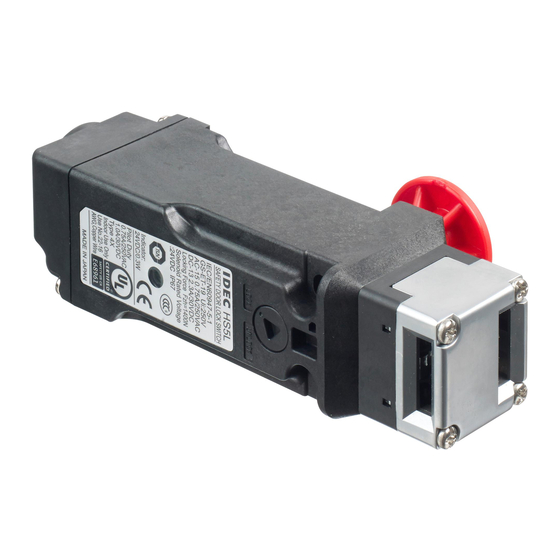
Solenoid Type Safety Switch
HS5L Series
Thank you for purchasing this IDEC product. Confirm that the delivered product is
what you have ordered. Read this instruction sheet to make sure of correct operation.
S A F E T Y P R E C A U T I O N S
In this operation instruction sheet, safety precautions are categorized in order of
importance to Warning and Caution :
WARNING
Warning notices are used to emphasize that improper operation may cause severe
personal injury or death.
CAUTION
Caution notices are used where inattention might cause personal injury or damage to
equipment.
1
Type
H S 5 L - V D 4 4 L M - G
Solenoid Voltage / Lock Mechanism
4 : 24V DC / Spring Lock
7Y : 24V DC / Solenoid Lock
Pilot Light Rated Voltage
4 : 24V DC
Contact Congifiguration
Main
Door monitor
Lock monitor
circuit
circuit
circuit
-
1NC
1NC
-
2NC
-
-
1NC,1NO
-
-
-
2NC
-
1NC,1NO
1NC,1NO
-
1NC,1NO
2NC
-
2NC
1NC,1NO
-
2NC
2NC
-
3NC
1NC
-
2NC,1NO
1NC
-
1NC
2NC,1NO
1NC+1NC
-
-
1NC+1NC
-
1NO
1NC
-
-
1NC,1NO
1NC+1NC
1NO
1NO
1NC+1NC
1NO
1NC
1NC+1NC
1NC
1NO
1NC+1NC
1NC
1NC
1NC+1NC
2NC
-
1NC+1NC
1NC,1NO
-
1NC+1NC
-
1NC,1NO
-
1NO
1NC,1NO
-
1NO
2NC
-
1NC
1NC,1NO
-
1NC
2NC
-
2NC
1NC
-
1NC,1NO
1NC
-
-
2NC,1NO
*1 Only type No. on √ mark are supplied as standard.
Contact IDEC for the other if required.
CAUTION
Solenoid lock type
• This safety switch is designed to lock the actuator while the solenoid is energized
and to release it when deenergized.
• When the power to the solenoid is interrupted by accident, such as disconnection,
the lock is released before a machine stops ompletely. Then, the worker may be
exposed to hazards.
• This safety switch can be used only for limited applications which do not especially
need to be locked for safety.
*In order to verify if the
product you are interested in
is certified with the S mark,
please check the following
section on our website: "List
of type numbers certified
with the S mark"
Indicator Color
G : Green
Rear Unlock Button
Blank : Wi hout Rear Unlock Button
L : Rear Unlock Button
Circuit Code
Standard type
□
□
HS5L-
HS5L-
44M-G
44LM-G
XD
√
-
XF
-
-
XG
-
-
XH
√
√
VA
√
√
VB
√
√
VC
√
√
VD
√
√
VF
√
-
VG
√
-
VJ
√
-
DD
√
√
XB
-
-
XJ
-
-
A
-
-
B
-
-
C
-
-
D
-
-
F
-
-
G
-
-
J
-
-
TA
-
-
TB
-
-
TC
-
-
TD
-
-
TF
-
-
TG
-
-
TJ
-
-
Spring Lock Type Solenoid Lock Type
Rear Unlock Button
Solenoid Type Safety Switch
*
2
Specifications and Ratings
Applicable Standards
Standards for Use
Interlocking device Type
/ the level of coded
Applicable Directives
Operating Condition
Inpulse withstand voltage
‹Uimp›
Raed Insulation voltage‹Ui›
Thermal Current ‹th›
Contact Ratings
(Reference Values)
‹Ue, Ie›*2
Class of Protection
Operating Frequency
Operating Speed
B10d
Mechanical durability
Electrical Durability
Shock Resistance
Vibration Resistance
Actuator Tensile Strength
when Locked
Direct Opening Travel
□
HS5L-
7Y4M-G
Direct Opening Force
√
Contact Resistance
√
Degree of Protection
√
Conditional short circuit
√
current
√
Short-circuit Protective
√
Device
√
Rated Operating Voltage
√
Rated Current
√
Turn ON Voltage
√
Turn OFF Voltage
-
Rated Power Consumption
-
Rated Operating Voltage
Rated Current
-
Light Source
-
llumination Color
-
-
*2 Ratings approved by safety agencies
-
(1)TÜV/CCC rating
-
-
(2)UL , c-UL rating
-
-
-
-
(3)KOSHA rating
-
-
*3 Basic insulation of 2.5kV impuise withstand circuits and between contact circuit
-
SELV(safety extra low voltage) or circuits (such as 230V AC circuits) at the same
time, the SELV or PELV arequirements are met any more.
-
*4 The actuator locking strength is rated at 1400N of static load. Do not apply a load
-
higher than the rated value. When a higher load is expected to work on the
actuator, provide an additional system consisting of another safety switch without
lock (such as the HS5D safety switch) or a sensor to detect door opening and stop
the machine.
*5 F1max is maximum force. The actuator's guard-locking force Fzh is calculated in
accodance with GS-ET-19:
*6 Make sure that a fast acting fuse for short-circuit protection trips before
overhea ing of he wires.
EN ISO / ISO14119, IEC60947-5-1, EN60947-5-1,
GS-ET-19,UL508, CSA C22 2 No.14, GB 14048. 5
IEC60204-1/EN60204-1
Type 2 Interlocking device
/ low level coded actuator (EN ISO / ISO14119)
Low Voltage Directive, Machinery Directive
Operating Temperature
Operating Humidity
Pollution Degree
Altitude
2.5kV (Between ground and LED, solenoid circuit : 0.5kV)
250V (Between ground and LED, solenoid circuit : 30V)
2.5A
AC Resistive load (AC12)
Inductive load (AC15)
DC Resistive load (DC12)
Inductive load (DC13)
Class II (IEC61140) *3
900 operations/hour
0.05 to 1.0 m/s
2,000,000 (ISO 13849-1 Annex C Table C.1)
2,000,000 operations minimum (GS-ET-19)
The Rear Unlock Button: 3000 operations
minimum (Type HS5L-
100,000 operations min. (AC-12 250V/1.5A)
2,000,000 operations min. (AC/DC 24V 100mA)
(900 operations / hour)
Operating Extremes: 100m/s
Operating Extremes:10 to 55 Hz, half amplitude 0.35mm
Damage Limits: 30 Hz, half amplitude 1.5mm
Fzh=1,400N minimum
F1max=1820N minimum (GS-ET-19) *4, *5
(Fzh=500N minimum: HS9Z-A55 actuator)
11 mm minimum (actuator: HS9Z-A51,A5P)
12 mm minimum (for other actuators)
120N minimum
50 mΩ maximum (initial value)
IP67 (IEC60529) , Type 4X Indoor Use Only
50A(250V)
Use 250V / 10A fast acting type fuse *6
DC24V 100% duty cycle
200 mA (initial value)
Rated voltage x 85% maximum (at 20°C)
Rated voltage x 10% minimum (at 20°C)
Approx. 5W
DC24V 100% duty cycle
10 mA
LED
Green
AC-15 250V/0.75A
DC-13 30V/2.3A
AC-15 250V/0.75A : Pilot Duty
DC-13 30V/1A : Pilot Duty
The M20 threaded opening must be filled by a Listed or
Recognized Component Liquid-Tight Flexible Cord Fitting
in order to maintain the Tye 4X Indoor use only rating.
AC-15 250V/0.75A
DC-13 30V/1A
maximum force (F1max)
Fzh
=
Safety coefficient (=1 3)
2016.04
B-1715(3)
-25 to +55°C (no freezing)
20 to 95%RH (no condensation)
3 (Inside 2)
2000m maximum
30V
125V
250V
-
2.5A
1.5A
-
1.5A
0.75A
2.5A
1.1A
0.55A
2.3A
0.55A
0.27A
□
L)
, Damage Limits: 1000m/s
2
2
( 1 / 8 )
Advertisement
Table of Contents

Related Manuals for IDEC HS5L Series


Summary of Contents for IDEC HS5L Series
- Page 1 S mark" Altitude 2000m maximum Thank you for purchasing this IDEC product. Confirm that the delivered product is what you have ordered. Read this instruction sheet to make sure of correct operation. Inpulse withstand voltage 2.5kV (Between ground and LED, solenoid circuit : 0.5kV) ‹Uimp›...
- Page 2 INSTRUCTION SHEET - HS5L Series 2016.04 Solenoid Type Safety Switch B-1715(3) CAUTION Mounting Examples • After installing the rear unlock button, apply Loctite to the screw so that the screw • Install the interlock switch on the immovable machine or guard, and install the does not become loose.
- Page 3 (Door movement) CAUTION ≤ 3.3mm HS9Z-A51 HS9Z-A52 • HS5L Series Safety Switches are Type 2 low-level coded interlocking devices (EN HS9Z-A51A ≤ 4.6mm ISO / ISO14119). The following system installation & mounting instructions are EN HS9Z-A52A ISO / ISO14119 requirements to prevent function failure from the interlock switch.
- Page 4 INSTRUCTION SHEET - HS5L Series 2016.04 Solenoid Type Safety Switch B-1715(3) CAUTION • Contact operation shows the HS9Z-A51 actuator. (For other actuators, add 1.3 mm to contact operation.) • Install the HS5L to ensure that a worker can operate the rear unlock button from •...
- Page 5 INSTRUCTION SHEET - HS5L Series 2016.04 Solenoid Type Safety Switch B-1715(3) CAUTION Wiring • When using wire with insulation Terminal wiring method diameter of Φ2.0mm or less, do not Incorrect Correct • Terminal NO. insert the wire too deep where the insulation inserts into the spring clamp ‹4 contact type›...
- Page 6 INSTRUCTION SHEET - HS5L Series 2016.04 Solenoid Type Safety Switch B-1715(3) Connecters' mounting method CAUTION 1. Loosen connecter A and connecter B, and insert the cable into these pieces in the Safety following order : • Make sure not to lose any screw when...
- Page 7 INSTRUCTION SHEET - HS5L Series 2016.04 Solenoid Type Safety Switch B-1715(3) Dimensions (mm) 3-M4 Safety Switch Safety Switch dimensions Mounting Holes 42.2 □ 44.5 Type : HS5L- 86.5 41 5 36 2 86.5 2-M4 Actuator HS9Z-A52 Mounting Holes Actuator ±1...
- Page 8 Heselstuecken 8, D-22453 Hamburg, Germany position. Remove after the actuator DECLARATION OF CONFORMITY position is determined. We, IDEC CORPORATION 2-6-64, Nishimiyahara Yodogawa-ku,Osaka 532-0004, Japan declare *15 The direction of adjustable angle can be under our sole responsibility that the product: changed...
Need help?
Do you have a question about the HS5L Series and is the answer not in the manual?
Questions and answers