Table of Contents

Related Manuals for Mitsubishi Electric ME96SSRB-MB


Summary of Contents for Mitsubishi Electric ME96SSRB-MB
- Page 1 Electronic Multi-Measuring Instrument MODEL ME96SSRB-MB User's Manual: Detailed Edition Before use, you should read this user’s manual carefully ● to properly operate this instrument. Be sure to forward the manual to the end user.
-
Page 2: Check Your Delivery
Installing the optional plug-in module enables various input or output. If you need it, consult with your supplier. ME-4201-NS96, ME-0052-NS96, and ME-0040C-NS96, which are optional plug-in modules for ME96NSR and ME96NSR-MB, are not available for ME96SSRB-MB. I/O specifications Model type... -
Page 3: Features
Features The instrument measures load status by wiring the secondary sides of VT (Voltage Transformer) and CT (Current Transformer) in the power receiving and distribution system and displays various measured values. The instrument supports Active Energy Class 0.5S and harmonic measurement (1st to 19th). ... -
Page 4: Table Of Contents
Table of Contents Check your delivery ..............................1 Optional plug-in module ............................1 Features .................................. 2 Trademark ................................2 Table of Contents ..............................3 Safety Precautions ..............................5 EMC Directive Instruction ............................9 Precautions for KC mark............................9 Table for measuring element code ........................10 1. - Page 5 Table of Contents 5.1.13. Demand Time Period and Demand Value of Current demand ............78 Usage Depending on the Application (Alarm, Periodic Active Energy, Rolling Demand, Operating Time, Password, etc.) ..........................79 5.2.1. Upper/Lower Limit Alarm Display and Action ................79 5.2.2.
-
Page 6: Safety Precautions
Safety Precautions Before use, read these instructions carefully to properly operate the instrument. Be sure to follow the precautions described here for personnel and product safety. Keep this manual ready to hand and accessible for future use at all times. Be sure to forward the manual to the end user. - Page 7 Safety Precautions ■Precautions on Installation and wiring Be sure to read the instructions carefully before installation and wiring. A qualified electrician must install and wire the instrument for safety. Supply power to the instrument after completing its assembly work on a cabinet door. ...
- Page 8 Safety Precautions In order to prevent invasion of noise, MODBUS RTU communication cables, auxiliary power supply cables, and other signal cables must not be placed close to or bound together with power lines or high voltage lines. When lying parallel to the power lines or high voltage lines, refer to the following table for the separation distance.
- Page 9 Safety Precautions ■Precautions on storage To store the instrument, turn off the power supplies of auxiliary power and input circuit, remove the wires from the terminals, and then put them in a plastic bag. For long-time storage, avoid the following places. Otherwise, there is danger of an instrument failure or reduced product life time.
-
Page 10: Emc Directive Instruction
This device has undergone a conformity assessment for use in a commercial environment and may cause radio wave interference when used in a home environment. Applicant for KC mark : MITSUBISHI ELECTRIC AUTOMATION KOREA CO.,LTD ■ Manufacturer : MITSUBISHI ELECTRIC CORPORATION ■... - Page 11 Table for measuring element code The following table shows a list of measuring element codes used in the manual. Measuring element code Measuring element name Current, 1-phase Current, 2-phase Current, 3-phase Current, N-phase Current, average Current demand, 1-phase Current demand, 2-phase Current demand, 3-phase Current demand, N-phase Current demand, average...
-
Page 12: Name And Function Of Each Section
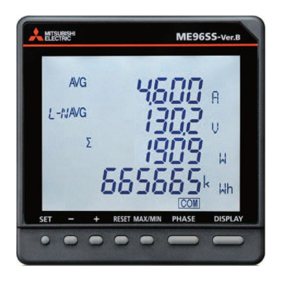
Name and Function of Each Section Name of Each Part <The instrument> ■The front of the unit LCD with backlight Operation buttons *For details, refer to 1.3 Function of Operation Buttons. ■The back of the unit MODBUS RTU communication terminals T/R+: MODBUS RTU communication terminal T/R-: MODBUS RTU communication terminal SG: MODBUS RTU signal ground terminal... - Page 13 Name and Function of Each Section 1.1. Name of Each Part <The optional plug-in module> ■The back view (Model type: ME-4210-SS96B, ME-0040C-SS96, ME-0052-SS96) Input/Output terminals (M Input/Output terminals ( E-4210-SS96B) ME-0040C-SS96) CH1+, CH1-: Analog output terminal DA: CC-Link communication terminal CH2+, CH2-: Analog output terminal DB: CC-Link communication terminal CH3+, CH3-: Analog output terminal...
- Page 14 Name and Function of Each Section 1.1. Name of Each Part ■The side/back view (Model type: ME-0000BU25-SS96) Slot for SD memory card LED indicators (Refer to 1.4 LED Display of Optional Plug-in Module.) LOG. SD C. BAT.
-
Page 15: Lcd Function
Name and Function of Each Section LCD Function Note: The above display is an example for explanation. Name of each part Function LEAD status Light up on the reactive energy (imported lead)/ (exported lead) screen. LAG status Light up on the reactive energy (imported lag)/ (exported lag) screen. Built-in logging status Light up when the built-in logging function is operating Digital element display... -
Page 16: Function Of Operation Buttons
Name and Function of Each Section Function of Operation Buttons + RESET MAX/MIN PHASE DISPLAY - The function of each operation button varies depending on how to press the button. SET button RESET button PHASE button +/- button MAX/MIN button DISPLAY button <Meaning of marks>... - Page 17 1. Name and Function of Each Section 1.3. Function of Operation Buttons Note: During backlight off mode, pressing any operation button first turns on the backlight. In addition, pressing any button again enables the use of the functions in the above table. When you execute a function such as ‘Reset Max/Min value’...
-
Page 18: Led Display Of Optional Plug-In Module
1. Name and Function of Each Section LED Display of Optional Plug-in Module ■LED (ME-0000MT-SS96) Name Function ERR. LED Indicate the communication status of ME-0000MT-SS96. Normal The following MODBUS TCP communication errors occur: ・There is an abnormality in the MODBUS TCP application protocol head part. - Page 19 1. Name and Function of Each Section LED Display of Optional Plug-in Module ■LED (ME-0000BU25-SS96) Name Function LOG. LED Indicate the logging operation status Logging is operating. Logging operation stops Low-speed The setting change of logging conditions has blinking been completed. (0.5 sec: on/ Blink for 5 seconds.
-
Page 20: Each Mode Function
Each Mode Function The instrument has the following operation modes. When auxiliary power is supplied, the operating mode is first displayed. Depending on the application, switch the operation mode to use. Mode Description Reference 5 Operation Operating This is a normal operation mode to display each measured value in digital mode numerical number. -
Page 21: How To Set Up
How to Set up Setting Flow For measurement, you must set settings such as phase wire system, VT/Direct voltage, and CT primary current in the setting mode. From the operating mode, enter the setting mode and then set necessary items. Any items not set remain in the factory default. - Page 22 How to Set up 3.1. Setting Flow <Setting Procedure> ① Press the buttons simultaneously for 2 seconds to enter the setting mode. RESET ② Select the setting menu number with the button. + - ③ Press the button to determine the setting menu number. ④...
-
Page 23: Setting Menu 1: Basic Setup (Settings For Phase Wire System, Display Pattern, Vt/Direct Voltage, And Ct Primary Current)
How to Set up Setting Menu 1: Basic Setup (Settings for Phase Wire System, Display Pattern, VT/Direct Voltage, and CT Primary Current) You will set the phase wire system, display pattern, VT/Direct voltage, CT primary current, and demand time period. In the operating mode, press simultaneously for 2 seconds or more to enter the following RESET... - Page 24 How to Set up Setting Menu 1: Basic Setup (Settings for Phase Wire System, Display Pattern, VT/Direct Voltage, and CT Primary Current) Continued from the previous page 2)When set to other than 3-phase 4-wire system *For 1-phase 2-wire system, P02 is not selectable. Additional Screen *Note P01 ○...
- Page 25 How to Set up Setting Menu 1: Basic Setup (Settings for Phase Wire System, Display Pattern, VT/Direct Voltage, and CT Primary Current) Continued form the previous page. (2) For measurement with VT <Secondary voltage setting> (a) When set to 3-phase 4-wire system (Phase voltage) 63.5 V 100 V 110 V...
- Page 26 How to Set up Setting Menu 1: Basic Setup (Settings for Phase Wire System, Display Pattern, VT/Direct Voltage, and CT Primary Current) Set the interval time period for rolling demand. *For details on the rolling demand, refer to 5.2.7. (1) Interval time period DISPLAY Setting range Setting step...
-
Page 27: Setting Menu 2: Communication Settings (Modbus Rtu Communication Settings)
How to Set up Setting Menu 2: Communication Settings (MODBUS RTU Communication Settings) <The installation conditions for optional plug-in module> No installation In the operating mode, press simultaneously for 2 seconds or more to enter the following RESET operation. Select 2 in the setting menu number. *Refer to the right figure. -
Page 28: Setting Menu 2: Communication Settings (Cc-Link Communication Settings)
How to Set up Setting Menu 2: Communication Settings (CC-Link Communication Settings) <The installation conditions for optional plug-in module> ME-0040C-SS96 installation In the operating mode, press simultaneously for 2 seconds or more to enter the following RESET operation. Select 2 in the setting menu number. *Refer to the right figure. -
Page 29: Setting Menu 2: Communication Settings (Modbus Tcp Communication Settings)
How to Set up Setting Menu 2: Communication Settings (MODBUS TCP Communication Settings) <The installation conditions for optional plug-in module> ME-0000MT-SS96 installation In the operating mode, press simultaneously for 2 seconds or more to enter the following RESET operation. Select 2 in the setting menu number. *Refer to the right figure. - Page 30 How to Set up 3.5. Setting Menu 2: Communication Settings (MODBUS TCP Communication Settings) Set whether default gateway exists. If there is default gateway on the Ethernet, set to ‘on’ ④MODBUS TCP to communicate with other network. Default gateway Set the address of default gateway. DISPLAY If you set ④MODBUS TCP Default gateway use to “oFF”, this screen will not be displayed.
-
Page 31: Setting Menu 3: Display Settings (Settings For Active/Reactive Energy And Harmonic Measurement)
How to Set up Setting Menu 3: Display Settings (Settings for Active/Reactive Energy and Harmonic Measurement) This section describes how to set the special measurement of active/reactive energy and harmonic display. In the operating mode, press simultaneously for 2 seconds or more to enter the following RESET operation. - Page 32 How to Set up Setting Menu 3: Display Settings (Settings for Active/Reactive Energy and Harmonic Measurement) DISPLAY Set whether to display the unbalance rate. Note: For 1-phase 2-wire system, ③Unbalance rate this setting is skipped. (Display) (Not display) display When you set to ‘on (Display)’, voltage/current unbalance rate can be displayed on the additional screen of display pattern.
-
Page 33: Setting Menu 4: Lcd Settings (Settings For Model Display, Version Display, Backlight, And Display Update Time)
You can check the model. This is for display only and not possible to change the settings. Refer to the following table for the corresponding model. (1) Second line DISPLAY Model ME96SSRB-MB (2) Fourth line Model name for optional plug-in module ①Model display Blank... -
Page 34: Setting Menu 5: Pulse/Alarm Settings (Settings For Upper/Lower Limit Alarm, Motor Starting Current Mask Function, And Pulse Output)
How to Set up Setting Menu 5: Pulse/Alarm Settings (Settings for Upper/Lower Limit Alarm, Motor Starting Current Mask Function, and Pulse Output) This section describes how to set the upper/lower limit alarm, backlight blinking during alarm, motor starting current, pulse output, and alarm output. In the operating mode, press simultaneously for 2 seconds or more to enter the following RESET... - Page 35 How to Set up Setting Menu 5: Pulse/Alarm Settings (Settings for Upper/Lower Limit Alarm, Motor Starting Current Mask Function, and Pulse Output) Set the alarm value of upper/lower limit alarm item 1. The following table shows the setting range. Setting Measuring element Setting range Step *...
- Page 36 How to Set up Setting Menu 5: Pulse/Alarm Settings (Settings for Upper/Lower Limit Alarm, Motor Starting Current Mask Function, and Pulse Output) Set the reset method to cancel an alarm. Reset method Description (For details, refer to 5.2.1 to 5.2.2.) (Settings) When alarm-generating conditions ⑥Alarm reset method...
- Page 37 How to Set up Setting Menu 5: Pulse/Alarm Settings (Settings for Upper/Lower Limit Alarm, Motor Starting Current Mask Function, and Pulse Output) Set the function of pulse/alarm output 1. When ME-4210-SS96B (optional plug-in module) is not installed, this screen is not displayed. ⑨Pulse/Alarm For alarm items at selecting alarm output, refer to output function 1...
- Page 38 How to Set up Setting Menu 5: Pulse/Alarm Settings (Settings for Upper/Lower Limit Alarm, Motor Starting Current Mask Function, and Pulse Output) Set the function of pulse/alarm output 2. When ME-4210-SS96B (optional plug-in module) is not installed, this screen is not displayed. ⑫Pulse/Alarm For alarm items at selecting alarm output, refer to 5.2.4.
-
Page 39: Setting Menu 6: Built-In Logging Settings
How to Set up Setting Menu 6: Built-in Logging Settings You will set the built-in logging. In the operating mode, press simultaneously for 2 seconds or more to enter the following RESET operation. Select 6 in the setting menu number. *Refer to the right figure. - Page 40 How to Set up Setting Menu 6: Built-in Logging Settings (1) Phase wire system: 3-phase 4-wire LP01 LP02 Logging item pattern Logging measuring data Wh (imported) Wh (imported) (Integrated value data) 1 Logging measuring data Wh (exported) Wh (exported) (Integrated value data) 2 Logging measuring data varh (imported lag) varh (imported lag)
- Page 41 How to Set up Setting Menu 6: Built-in Logging Settings Continued from the previous page. (3) Phase wire system: 1-phase 2-wire Logging item pattern LP01 LP02 Logging measuring data Wh (imported) Wh (imported) (Integrated value data) 1 Logging measuring data Wh (exported) Wh (exported) (Integrated value data) 2...
-
Page 42: Setting Menu 6: Analog Output Settings
How to Set up Setting Menu 6: Analog Output Settings <The installation conditions for optional plug-in module> ME-4210-SS96B installation You will set the analog output. In the operating mode, press simultaneously for 2 seconds or more to enter the following RESET operation. - Page 43 How to Set up 3.10 Setting Menu 6: Analog Output Settings (2) When set to other than 3-phase 4-wire system 1-phase 3-wire 1-phase 3-wire 3-phase 3-wire 1-phase 2-wire (1N2 display) (1N3 display) A(CH1) (CH1) (CH1) (CH1) V(CH2) W(CH3) PF(CH4) (CH2) (CH2)...
- Page 44 How to Set up 3.10 Setting Menu 6: Analog Output Settings Set the details for analog output CH1. *The following settings can be set separately from measuring items included in the display pattern. This setting is necessary when ②Analog output CH1 Output item is set to current, demand current, voltage, active power, reactive power, or power factor.
- Page 45 How to Set up 3.10 Setting Menu 6: Analog Output Settings Continued from the previous page. (4) When the output item is set to power factor, select an output range. Output item Setting range -0.5 to 1 to 0.5 -0 to 1 to 0 <Relationship with input and output>...
-
Page 46: Setting Menu 6: Optional Logging Settings
How to Set up Setting Menu 6: Optional Logging settings <The installation conditions for optional plug-in module> ME-0000BU-SS96 or ME-0000BU25-SS96 installation You will set the optional logging. In the operating mode, press simultaneously for 2 seconds or more to enter the following RESET operation. - Page 47 How to Set up 3.11 Setting Menu 6: Optional Logging settings Select a logging item pattern to set data for logging. Settable pattern: LP01 LP02 LP00 When setting to LP00, you can select any logging item. For details on LP00, refer to the following document. ・ME-0000BU-SS96 Logging function specifications┉┉┉LSPM-0092 ・ME-0000BU25-SS96 Logging function specifications┉LSPM-0106 For LP01 and LP02, the logging item pattern is defined as the following table.
-
Page 48: Setting Menu 7: Settings For Periodic Active Energy, Rolling Demand, And Digital Input/Output
How to Set up Setting Menu 7: Settings for Periodic active Energy, Rolling Demand, and Digital Input/Output You will set the periodic active energy, rolling demand, and digital input/output. In the operating mode, press simultaneously for 2 seconds or more to enter the following RESET operation. - Page 49 How to Set up 3.12 Setting Menu 7: Settings for Periodic active Energy, Rolling Demand, and Digital Input/Output Set whether to display contact input/output. When any optional plug-in module is not installed and when ME-0000MT-SS96, ME-0000BU-SS96 or ⑤Digital input/output display ME-0000BU25-SS96 is installed, this screen is not displayed.
-
Page 50: Setting Menu 8: Special Settings (Settings For Operating Time, Iec Mode, And Co Equivalent)
How to Set up Setting Menu 8: Special Settings (Settings for Operating Time, IEC Mode, and CO equivalent) You will set the operating time and IEC mode. In the operating mode, press simultaneously for 2 seconds or more to enter the following RESET operation. - Page 51 How to Set up 3.13. Setting Menu 8: Special Settings (Settings for Operating Time, IEC Mode, and CO equivalent) Set the threshold for operating time 2 count target. ⑤Operating time 2 The setting method is the same as ③Operating time 1 Threshold. Threshold According to this setting, calculation formulas and signs are changed.
-
Page 52: Setting Menu Cl: Preset Time Settings
How to Set up Setting Menu CL: Preset Time Settings You will set the time necessary when data logging is executed. When the built-in logging function is set to ‘oFF (Not use)’, and when ME-0000BU-SS96 or ME-0000BU25- SS96 (optional plug-in module) is not installed, this menu is not displayed. In the operating mode, press simultaneously for 2 seconds or more to enter the following RESET... - Page 53 How to Set up 3.14. Setting Menu CL: Current Time Settings Set the minute for time. time ⑥Present setting (Minute) Setting range (Tens place): 0 to 5 Setting range (Ones place): 0 to 9 Example for setting of tens place According to 3.1 Setting Flow,...
-
Page 54: Setting Confirmation Menu 1 To 9: Confirming The Settings In The Setting Menu 1 To 8 And 9 Test Mode
How to Set up Setting Confirmation Menu 1 to 9: Confirming the Settings in the Setting Menu 1 to 8 and 9 Test Mode Setting Confirmation In the operating mode, press for 2 seconds or more to execute the operation. In the setting confirmation menu, the screen switching and operation methods are the same as the setting menu 1 to Setting confirmation... -
Page 55: Initialization Of Related Items By Changing A Setting
How to Set up Initialization of Related Items by Changing a Setting When you change a setting, the related setting items and measuring data (maximum and minimum values) are initialized. For details, refer to the following table. Menu Menu 1 Menu 6 Menu 8 Menu 2... -
Page 56: Initialization Of All Settings
How to Set up Initialization of All Settings The following operation enables to reset all settings to the factory default. It is only for the settings. Measured active energy, reactive energy, and operating time are not changed. For details on the initialization of maximum and minimum values, refer to 3.16 Initialization of Related Items by Changing a Setting. -
Page 57: Settings For Special Display Pattern P00
How to Set up Settings for Special Display Pattern P00 If you want to set a display pattern other than P01 or P02, P00 is available to freely set display items. This setting is conducted in the setting menu 1. The explanation here begins with the settings for P00 at ②Display pattern in the setting menu 1. - Page 58 How to Set up 3.18. Settings for Special Display Pattern P00 Continued form the previous page (6) You will set up the display of screen 4-2. Select ‘yES’ with and then press + - *When the screen 2 is not necessary to display, select ‘no’...
-
Page 59: Example For Easy Setup
How to Set up Example for Easy Setup The following example illustrates an easy setup. ■Setting Example ・ Model: ME96SSRB-MB (without optional plug-in module) ・ Phase wire system: 3-phase 4-wire ・ Measuring element: A, V, W, PF ・ Input Voltage: 220/380 V ・... - Page 60 How to Set up 3.19. Example for Easy Setup MODBUS RTU The factory default is set to ‘1.’ Just press SET. Address MODBUS RTU The factory default is set to ‘19.2 kbps.’ Just press SET. Baud rates MODBUS RTU The factory default is set to ‘EVEn (even).’ Just press SET. Parity MODBUS RTU The factory default is set to ‘1.’...
-
Page 61: How To Use Test Mode
How to Use Test Mode The test mode has function useful for startup of equipment. The following table shows a list of functions in the test mode. Test menu Description For models with communication function, without measurement (voltage/current) 1. Communication test input, it is possible to return fixed numerical data. -
Page 62: Test Menu 1: Communication Test
4. How to Use Test Mode Test Menu 1: Communication Test Set the setting confirmation menu number to 9 to enter the test mode In the test mode, the following operation is available. Set the test menu number to 1. *Refer to the right figure. -
Page 63: Test Menu 2: Alarm Output/Digital Output Test
4. How to Use Test Mode Test Menu 2: Alarm Output/Digital Output Test In the test mode, the following operation is available. ・ When ME-4210-SS96B or ME-0052-SS96 (optional plug-in module) is not installed, this menu is not displayed. ・ Even when ME-4210-SS96B (optional plug-in module) is installed, if alarm output is not set at the setting menu 5: Pulse/Alarm output function, this menu will not be displayed. -
Page 64: Test Menu 3: Zero/Span Adjustment For Analog Output
4. How to Use Test Mode Test Menu 3: Zero/Span Adjustment for Analog Output In the test mode, the following operation is available. When ME-4210-SS96B (optional plug-in module) is not installed, this screen is not displayed. Set the test menu number to 3. *Refer to the right figure. -
Page 65: Test Menu 4: Analog Output Test
4. How to Use Test Mode Test Menu 4: Analog Output Test In the test mode, the following operation is available. When ME-4210-SS96B (optional plug-in module) is not installed, this menu is not displayed. Set the test menu number to 4. *Refer to the right figure. -
Page 66: Test Menu 5: Pulse Output Test
4. How to Use Test Mode Test Menu 5: Pulse Output Test In the test mode, the following operation is available. ・ When ME-4210-SS96B (optional plug-in module) is not installed, this menu is not displayed. ・ Even when ME-4210-SS96B (optional plug-in module) is installed, if pulse output is not set at the setting menu 5: Pulse/Alarm output function, this menu will not be displayed. -
Page 67: Test Menu 6: Function For Determining Incorrect Wiring
4. How to Use Test Mode Test Menu 6: Function for Determining Incorrect Wiring In the test mode, the following operation is available. Set the test menu number to 6. *Refer to the right figure. Test Menu When either a voltage input or a current input is incorrectly wired, this function automatically determines incorrect wiring and the incorrect part is displayed on the screen. - Page 68 4. How to Use Test Mode 4.6. Test Menu 6: Function for Determining Incorrect Wiring Continued from the previous page. ■It is not possible to detect incorrect wiring If the screen is displayed as the following, it is not possible to detect incorrect wiring. Check measurement (voltage/current) input or press to check ②Support display for +...
- Page 69 4. How to Use Test Mode 4.6. Test Menu 6:Function for Determining Incorrect Wiring Continued from the previous page. ■Phase angle The phase angle is displayed clockwise based on V (0 degree). angle between V and V ∠V 32-phase angle between I and V ∠I 1-phase...
-
Page 70: Incorrect Wiring Patterns Detected By ①Pattern Display Of Incorrect Wiring
4. How to Use Test Mode 4.6. Test Menu 6: Function for Determining Incorrect Wiring 4.6.1. Incorrect Wiring Patterns Detected by ①Pattern display of incorrect wiring This function is designed with the assumption that either a current input or a voltage input is incorrectly wired in positive phase sequence. - Page 71 4. How to Use Test Mode 4.6. Test Menu 6:Functions for Determining Incorrect Wiring 4.6.1. Incorrect wiring patterns detected by ①Pattern display of incorrect wiring ■For 3-phase 3-wire system No. Wiring diagram No. Wiring diagram No. Wiring diagram Normal Reverse connection between terminals P1 and P2 Reverse connection of 1 side VT Reverse connection of 1 side CT Reverse connection between terminals P2 and P3...
- Page 72 4. How to Use Test Mode 4.3. Test Menu 6:Functions for Determining Incorrect Wiring 4.3.1. Incorrect wiring patterns detected by ①Pattern display of incorrect wiring ■For 1-phase 3-wire system *1 No. Wiring diagram No. Wiring diagram No. Wiring diagram Normal Switch between 1 side CT and 3 side CT Reverse connection between terminals P1 and P3...
-
Page 73: Operation
Operation Basic Operation The display item and order vary The following charts illustrate how to use basic operation. depending on the phase wire system, display pattern, and additional screen. 5.1.1. How to Switch the Measurement Screen For details on the display pattern, refer Press to switch the measurement screen. -
Page 74: How To Display The Cyclic Mode
Operation 5.1. Basic Operation 5.1.3. How to Display the Cyclic Mode In the cyclic mode, the measurement screen or phase display automatically switches every 5 seconds. When you press for 2 seconds, the screen enters the cyclic display mode of measurement screen. DISPLAY Pressing for 2 seconds enters the cyclic display mode of phase. -
Page 75: Harmonics Display
Operation 5.1. Basic Operation 5.1.4. Harmonics Display The harmonic RMS value and distortion ratio (content rate) can be displayed. To display them, you must set the harmonics display. For details on the settings, refer to 3.6. ■Measuring elements Harmonic Harmonic current Harmonic current N-phase... -
Page 76: Maximum/Minimum Value Display
Operation 5.1. Basic Operation 5.1.5. Maximum/Minimum Value Display On the Max/Min value screen, a maximum value, present value, and minimum value are displayed in one screen by measuring item. However, for harmonics, the following maximum values only are displayed. ・Harmonic current: The total/1 to 19 RMS value of the phase where a value was the largest in every phase. -
Page 77: Active Energy/Reactive Energy/Apparent Energy Display
Operation 5.1. Basic Operation 5.1.8. Active Energy/Reactive Energy/Apparent Energy Display Display type ■ The following table shows the display type of active/reactive/apparent energy based on the full-load power. α x (VT primary voltage) x (CT primary current) Full-load power [kW] = α: 1 1-phase 2-wire 1000 2 1-phase 3-wire... -
Page 78: How To Reset Active/Reactive/Apparent Energy To Zero
Operation 5.1. Basic Operation 5.1.10. How to Reset Active/Reactive/Apparent Energy to Zero When you press , and simultaneously for 2 seconds, active, reactive, and apparent RESET PHASE energy values will be reset to zero. When password protection is enabled, the values are reset after you enter the password. In addition, communication function enables to reset all active, reactive, and apparent energy values to zero. -
Page 79: Each Measuring Item Display During Power Transmission
Operation 5.1. Basic Operation 5.1.12. Each Measuring Item Display during Power Transmission The following table shows symbol display (±) for each measured value according to the power transmission state. For details on how to switch the 2 quadrant/4 quadrant measurement, refer to 3.6. For details on how to switch IEC mode, refer to 3.13. -
Page 80: Usage Depending On The Application (Alarm, Periodic Active Energy, Rolling Demand, Operating Time, Password, Etc.)
Operation Usage Depending on the Application (Alarm, Periodic Active Energy, Rolling Demand, Operating Time, Password, etc.) The following shows how to use the instrument depending on the application. 5.2.1. Upper/Lower Limit Alarm Display and Action When the set upper/lower limit alarm value is exceeded, the display starts to blink and an alarm is output. *For details on how to set the upper/lower limit alarm, refer to 3.8. - Page 81 Operation 5.2. Usage Depending on the Application (Alarm, Periodic Active Energy, Rolling Demand, Operating Time, Password, etc.) ■Monitored phase of upper/lower limit alarm item The phase for monitoring the upper/lower limit alarm varies depending on the measuring item. For details, refer to the following table. Monitored phase 3-phase 1-phase...
-
Page 82: How To Cancel The Upper/Lower Limit Alarm
Operation 5.2. Usage Depending on the Application (Alarm, Periodic Active Energy, Rolling Demand, Operating Time, Password, etc.) 5.2.2. How to Cancel the Upper/Lower Limit Alarm The alarm cancellation method differs depending on the alarm reset setting. In addition to the following methods, communication function is available to cancel the upper and lower limit alarm Alarm reset method How to cancel... -
Page 83: Periodic Active Energy Display
Operation 5.2. Usage Depending on the Application (Alarm, Periodic Active Energy, Rolling Demand, Operating Time, Password, etc.) 5.2.5. Periodic Active Energy Display Active energy can be measured by dividing into a maximum of three time periods. Even when the periodic active energy display is set to ‘oFF (Not display)’, the periodic active energy is measured. -
Page 84: Rolling Demand Display And Calculation
Operation 5.2. Usage Depending on the Application (Alarm, Periodic Active Energy, Rolling Demand, Operating Time, Password, etc.) 5.2.7. Rolling Demand Display and Calculation Rolling demand is calculated by dividing the active/reactive/apparent energy during a specified period (interval) *1 by the length of that period. For block interval demand, you specify a period of time interval (or block) that this instrument uses for the demand calculation. -
Page 85: Rolling Demand Predict Value
Operation 5.2. Usage Depending on the Application (Alarm, Periodic Active Energy, Rolling Demand, Operating Time, Password, etc.) 5.2.8. Rolling Demand Predict Value The rolling demand provides present, last, predict, and peak demand values. The predicted demand value is calculated for the end of the present interval for each rolling demand, taking into account the energy consumption so far within the present (partial) interval and the present rate of consumption. -
Page 86: Operating Time Display
Operation 5.2. Usage Depending on the Application (Alarm, Periodic Active Energy, Rolling Demand, Operating Time, Password, etc.) 5.2.11. Operating Time Display According to the value set to the operating time count target (AUX, A, or V), measuring time is counted and displayed as operating time of load. -
Page 87: Digital Input/Output Status Display And Action
Operation 5.2. Usage Depending on the Application (Alarm, Periodic Active Energy, Rolling Demand, Operating Time, Password, etc.) 5.2.15. Digital Input/Output Status Display and Action The contact status can be displayed by signal inputs such as the opening/closing signal of breaker or the alarm signal of overcurrent relay to the digital input (DI) terminal. -
Page 88: Password Protection Setting
Operation 5.2. Usage Depending on the Application (Alarm, Periodic Active Energy, Rolling Demand, Operating Time, Password, etc.) 5.2.18. Password Protection Setting In the operating mode, when you press simultaneously for 2 seconds or more and then RESET PHASE enter the password, the password protection can be set. The password of the factory default is ‘0000.’... -
Page 89: Built-In Logging Function
Operation 5.2. Usage Depending on the Application (Alarm, Periodic Active Energy, Rolling Demand, Operating Time, Password, etc.) 5.2.19. Built-in Logging Function This built-in logging function stores measured data as logging data in the internal non-volatile memory. The data to be stored as events occurred in this instrument are alarm log, the recorded time of the Max/Min value, and system log data. -
Page 90: Others
Others Display Pattern List When you set the display pattern in the setting menu 1 and the additional screens in the setting menu 3, 7, and 8, the screen is switched from No.1 in the following table in ascending order by pressing DISPLAY [When set to 3-phase 4-wire system] Screen set by display pattern... - Page 91 Others 6.1. Display Pattern List [When set to other than 3-phase 4-wire system] Screen set by display pattern Display pattern No.1 No.2 No.3 No.4 No.5 No.6 varh Aavg DAavg Vavg varh Arbitrary 1 Arbitrary 1 Arbitrary 1 Arbitrary 1 2nd Arbitrary 1 Arbitrary 1 Arbitrary 1 Arbitrary 1 Arbitrary 1 Arbitrary 1 Arbitrary 1 Arbitrary 1 Arbitrary 2 Arbitrary 2 Arbitrary 2 Arbitrary 2 Note1: For 1-phase 2-wire system, the display pattern of P02 is not selectable.
- Page 92 Others 6.1. Display Pattern List Note4: When you add an additional screen, the screen number is added. Note5: In the table, ‘Wh’ and ‘varh’ indicate active energy (imported) and reactive energy (imported lag) respectively. Note6: The additional screens of Wh, varh, and VAh of P00 are displayed by setting each item as display element. Note7: The display of additional screens of No.20 and 21 in the above table varies depending on the setting of the phase wire system as the following table.
-
Page 93: Standard Value
Others Standard Value The standard value is calculated according to the measuring item as the following table. ■Standard value for each measuring item ■Intrinsic power value Measuring element Standard value *Note2 Intrinsic power Phase wire system secondary Rated voltage value (100%) current Current, Current demand CT primary current setup value... - Page 94 Others 6.2. Standard Value ■Standard value for current/current demand and STEP Setting range: -10STEP to +3STEP <Example> When the standard value is 100 A (0STEP), the range is 45 A (-10STEP) to 160 A (+3STEP). Current standard value (1/3) Current standard value (2/3) Current standard value (3/3) STEP Unit: A...
- Page 95 Others 6.2. Standard Value ■Standard value for voltage and STEP Setting range: -18STEP to +10STEP <Example> When the standard value is 100 V (0STEP), the range is 20 V (-18STEP) to 320 V (+10STEP). Voltage standard value (1/3) Voltage standard value (2/3) Voltage standard value (3/3) STEP Unit: V...
- Page 96 Others 6.2. Standard Value ■Standard value for active/reactive/apparent power and STEP Setting range: -18STEP to +3STEP <Example> When the standard value is 1000 W (0STEP), the range is 200 W (-18STEP) to 1600 W (+3STEP). Active power Active power Active power Active power Active power standard value (2/5)
-
Page 97: Measuring Items And The Corresponding Display/Output
Others Measuring Items and the Corresponding Display/Output The following table shows measuring items and the corresponding display/output. ○: Display/output is possible. Blank: Display/output is not possible. Inst: Instantaneous value Display item Analog 3-phase 3-phase 3-wire (2CT) Measuring item Pulse 3-phase 4-wire 3-phase 3-wire (3CT) 1-phase 2-wire Communication... - Page 98 Others 6.3. Measuring Items and the Corresponding Display/Output Note1: Each harmonic degree represents the odd degrees of the 1st to 31st RMS value and the 3rd to 31st content rate. Note2: The imported lag and imported lead include the exported lead and exported lag respectively. Note3: For the measuring items monitored by communication function, refer to the specifications of each communication function.
-
Page 99: Instrument Operation
Others Instrument Operation ■The instrument operation in other than operating mode Analog output Alarm contact Pulse output Situation Measurement Display For a few seconds just Not measure Not display There Open Not output after turning on the approximately 100% auxiliary power or more output until *The backlight lights the internal voltage... -
Page 100: Troubleshooting
Others Troubleshooting If you observe abnormal sound, odor, smoke, or heat generation from the instrument, turn off the power at once. In addition, if you are considering sending the instrument in for repair, check the following points before it. Situation Possible cause Solution The display does not light... - Page 101 Others 6.5. Troubleshooting Situation Possible cause Solution In the setting mode, setting When blinks at the bottom left of Enter the setting mode to change change is not possible. the screen, it is in the setting settings. confirmation mode. Therefore, setting change is not possible.
- Page 102 Others 6.5. Troubleshooting Situation Possible cause Solution The present time is not set. Set the present time, and the clock Although LOG on the LCD status will light After this lights up, the clock status instrument restarts by applying the goes off.
-
Page 103: Installation
Installation Dimensions ■ME96SSRB-MB [mm] ■Optional plug-in module ME-4210-SS96B ME-0040C-SS96 ME-0052-SS96 [mm]... - Page 104 Installation 7.1. Dimensions ■Optional plug-in module ME-0000MT-SS96 [mm] ■Optional plug-in module ME-0000BU-SS96 ME-0000BU25-SS96 [mm]...
-
Page 105: How To Install
Installation How to Install 7.2.1. Mounting Hole Dimensions The right figure shows the hole drilling dimensions of the panel. Use a panel with a thickness of 1.6 mm to 4.0 mm for installation. 7.2.2. Mounting Position The contrast of LCD display changes depending on the angle of view. Install the instrument in a location where you can easily see it. -
Page 106: How To Connect Wiring
Installation How to Connect Wiring 7.3.1. Specifications on the Applicable Electrical Wire Screw Tightening Parts Wire for use type torque ・Used with crimp-type terminals: AWG 26 to 14 The terminals of this *Two-wire connection is possible. instrument: Applicable crimp-type terminals: For M3 screw ・Auxiliary power with an outer diameter of 6.0 mm or less. - Page 107 Installation 7.3. How to Connect Wiring Do not work under live wires. Do not connect the terminals or RJ 45 connectors under live line conditions. In addition, do not insert or remove a SD memory card under hot line conditions. Otherwise, there is danger of electric shock, burn injury, burnout of the instrument, or a fire.
-
Page 108: Wiring Diagram
Installation Wiring Diagram ■Rated voltage for each phase/wire system Phase/Wire Connection Rated voltage Figure 3-phase 4-wire Star max 277 V AC (L-N) /480 V AC (L-L) Figure 1 Delta max 220 V AC (L-L) Figure 2 3-phase 3-wire Star max 440 V AC (L-L) Figure 3 1-phase 3-wire ―... - Page 109 Installation 7.4. Wiring Diagram ■3-phase 4-wire system, direct input ①Auxiliary power supply 100 V AC to 240 V AC or 100 V DC to 240 V DC ②Fuse (recommendation) Rated current: 0.5 A, Rated breaking capacity: 250 V AC 1,500 A / 250 V DC 1,500 A (a UL certified product) ③If MODBUS RTU devices do not have the SG terminal, the wiring between SG terminals is not necessary.
- Page 110 Installation 7.4. Wiring Diagram ■3-phase 3-wire system, direct input, 2CT ①Auxiliary power supply 100 V AC to 240 V AC or 100 V DC to 240 V DC ②Fuse (recommendation) Rated current: 0.5 A, Rated breaking capacity: 250 V AC 1,500 A / 250 V DC 1,500 A (a UL certified product) ③If MODBUS RTU devices do not have the SG terminal, the wiring between SG terminals is not necessary.
- Page 111 Installation 7.4. Wiring Diagram ■1-phase 3-wire system ①Auxiliary power supply 100 V AC to 240 V AC or 100 V DC to 240 V DC ②Fuse (recommendation) Rated current: 0.5 A, Rated breaking capacity: 250 V AC 1,500 A / 250 V DC 1,500 A (a UL certified product) ③If MODBUS RTU devices do not have the SG terminal, the wiring between SG terminals is not necessary.
- Page 112 Installation 7.4. Wiring Diagram ■Optional plug-in module: ME-4210-SS96B ■Optional plug-in module: ME-0040C-SS96...
- Page 113 Installation 7.4. Wiring Diagram ■Optional plug-in module: ME-0052-SS96 ■Optional plug-in module: ME-0000MT-SS96 ■Optional plug-in module: ME-0000BU-SS96 ME-0000BU25-SS96...
- Page 114 Installation 7.4. Wiring Diagram For Input 1. The voltage input terminals of 3-phase 3-wire system are different from those of other systems. 2. If the VT and CT polarities are incorrect, measurement will not be correctly executed. Note 3. Do not wire the NC terminal. 4.
- Page 115 Installation 7.4. Wiring Diagram For MODBUS TCP Communication 1. For 100 Mbps communication with 100 BASE-TX connection, a communication error may occur depending on the installation environment due to the effect of high frequency noise from devices other than this instrument. To prevent the effect of high frequency noise, take the following measures against it when configuring a network system.
-
Page 116: How To Insert/Remove Sd Memory Card
Insert the SD memory card straight into the SD memory slot until you hear a click. ・Be sure to use a SD memory card, EMU4-SD2GB, produced by Mitsubishi Electric Corporation. Using a SD memory card not produced by Mitsubishi Electric Corporation CAUTION may cause a trouble such as data corruption in the card or system stop. -
Page 117: Specifications
Specifications Product Specifications Type ME96SSRB-MB 3-phase 4-wire, 3-phase 3- wire (3CT, 2CT), 1-phase 3- wire, 1-phase 2- wire Phase wire system (common use) Current 5 A AC, 1 A AC (common use) 3-phase 4- wire: max 277/480 V AC 3-phase 3- wire: (DELTA) max 220 V AC, (STAR) max 440 V AC... - Page 118 Specifications 8.1. Product Specifications Item Specifications Integrated value data: 5 items, Data other than integrated value: 15 items, Measurement data Total: Max. 20 items Alarm log The number of the set alarms The total is 19 elements: Current Max/Min (AVG), Line voltage Max/Min (AVG), Number of Phase voltage Max/Min (AVG), Total active power Max/Min (AVG), Total power logging items...
- Page 119 Specifications 8.1. Product Specifications Note1: The accuracy class value represents the ratio to the rated value (100%). Note2: For measurement where the harmonic distortion ratio (content rate) is 100% or more, the class can exceed ±1.0%. Note3: Harmonic current cannot be measured without voltage input. Note4: If the conventional ME-4210-SS96 (Optional plug-in module) is used, the safety certification requirements of CE marking and UL standards cannot be met.
-
Page 120: Compatible Standards
Specifications Compatible Standards Electromagnetic Compatibility Emissions EN61326-1/ EN 55011/CISPR 11, Radiated Emission FCC Part15 Subpart B Class A EN61326-1/ EN 55011/CISPR 11 Conducted Emission FCC Part15 Subpart B Class A Harmonics Measurement EN61000-3-2 Flicker Meter Measurement EN61000-3-3 Immunity Electrostatic discharge Immunity EN61326-1,EN IEC 61000-6-2/EN61000-4-2 Radio Frequency Electromagnetic field Immunity EN61326-1,EN IEC 61000-6-2/EN61000-4-3... -
Page 121: Cc-Link Communication Specifications For Optional Plug-In Module
Specifications CC-Link Communication Specifications for optional plug-in module Item Specifications CC-Link version Ver. 1.10 Ver. 2.00 Number of occupied stations 1 station, remote device station Expanded cyclic setting Octuple Remote station number 1 to 64 Transmission speed 156 k, 625 k, 2.5 M, 5 M, 10 Mbps Maximum number of stations 42 stations (In case of connecting only remote device station occupied by 1 per master station... -
Page 122: Logging Specifications For Optional Plug-In Module
*2. It represents a period until a 2 GB SD memory card capacity is exceeded under the constant connection. *3. Be sure to use a SD memory card, EMU4-SD2GB, produced by Mitsubishi Electric Corporation. Using other SD memory cards not produced by Mitsubishi Electric Corporation may cause a trouble such as data corruption in the card or system stop. -
Page 123: Input / Output Specifications (Optional Plug-In Module)
Specifications Input / output specifications (optional plug-in module) Item Specifications Output specifications 4 mA to 20 mA Analog output Load resistance 600 Ω or less Response time 1 second or less (Hz: 2 seconds or less, HI, HV: 5 seconds or less) Switch type No-voltage a-contact Pulse/Alarm... -
Page 124: Setting Table (Factory Default Settings And Customer's Notes Settings)
Specifications Setting Table (Factory Default Settings and Customer’s Notes Settings) Setting menu No. Setting item Factory default setting Customer’s notes Phase wire system 3P4 (3-phase 4-wire) Display pattern 1.2.1 Pattern P00 ― VT/Direct voltage no (Without VT) 1.3.1 Direct voltage 220/380 V 1.3.2 VT secondary voltage... - Page 125 Specifications 8.8. Setting Table (Factory Default Settings and Customer’s Notes Settings) Setting menu No. Setting item Factory default setting Customer’s notes Motor starting current delay function oFF (Not display) 5.8.1 Motor starting current threshold ― 5.8.2 Motor starting p current delay time ―...
- Page 126 Specifications 8.8. Setting Table (Factory Default Settings and Customer’s Notes Settings) Setting menu No. Setting item Factory default setting Customer’s notes Periodic active energy display oFF (Not display) 7.1.1 Periodic active energy switching settings non (Non-switching) Rolling demand display oFF (Not display) 7.2.1 Rolling demand time period oFF (Manual)
-
Page 127: Appendix
Appendix ME96SS Calculation Method (3-Phase Unbalanced System with Neutral) The following table shows general calculation definitions of electric energy measurement this instrument employs. Item Normal mode IEC (A) mode IEC (V) mode Notes − ∑ current phase p − ∑ Calculated neutral current −... -
Page 128: Optional Parts
Appendix Optional parts ■SD memory card Item Specifications Model EMU4-SD2GB Memory capacity 2 GB Weight Note: The unit of number is ‘mm.’... -
Page 129: A List Of Examples For Incorrect Wiring Display
Appendix A List of Examples for Incorrect Wiring Display 9.3.1. 3-phase 4-wire System *The shaded parts indicate influential parts caused by incorrect wiring. The dashed lines show incorrect wiring parts. At balanced load (V Connection (Note 1) Phase Angle Display Power Factor Voltage Display Current Display... - Page 130 Appendix 9.3. A List of Examples for Incorrect Wiring Display 9.3.1. 3-phase 4-wire System At balanced load (V Connection (Note 1) Phase Angle Display Power Factor Voltage Display Current Display Voltage Current Active Power Display (Input) Connection 1 side CT 2 side CT 3 side CT ∠V...
- Page 131 Appendix 9.3. A List of Examples for Incorrect Wiring Display 9.3.1. 3-phase 4-wire System At balanced load (V Connection (Note 1) Phase Angle Display Power Factor Voltage Display Current Display Voltage Current Active Power Display (Input) Connection 1 side CT 2 side CT 3 side CT ∠V...
- Page 132 Appendix 9.3. A List of Examples for Incorrect Wiring Display 9.3.1. 3-phase 4-wire System At balanced load (V Connection (Note 1) Phase Angle Display Power Factor Voltage Display Current Display Voltage Current Active Power Display (Input) Connection 1 side CT 2 side CT 3 side CT ∠V...
- Page 133 Appendix 9.3. A List of Examples for Incorrect Wiring Display 9.3.1. 3-phase 4-wire System At balanced load (V Connection (Note 1) Phase Angle Display Power Factor Voltage Display Current Display Voltage Current Active Power Display (Input) Connection 1 side CT 2 side CT 3 side CT ∠V...
- Page 134 Appendix 9.3. A List of Examples for Incorrect Wiring Display 9.3.1. 3-phase 4-wire System At balanced load (V Connection (Note 1) Phase Angle Display Power Factor Voltage Display Current Display Voltage Current Active Power Display (Input) Connection 1 side CT 2 side CT 3 side CT ∠V...
- Page 135 Appendix 9.3. A List of Examples for Incorrect Wiring Display 9.3.1. 3-phase 4-wire System At balanced load (V Connection (Note 1) Phase Angle Display Power Factor Voltage Display Current Display Voltage Current Active Power Display (Input) Connection 1 side CT 2 side CT 3 side CT ∠V...
- Page 136 Appendix 9.3. A List of Examples for Incorrect Wiring Display 9.3.1. 3-phase 4-wire System At balanced load (V Connection (Note 1) Phase Angle Display Power Factor Voltage Display Current Display Voltage Current Active Power Display (Input) Connection 1 side CT 2 side CT 3 side CT ∠V...
- Page 137 Appendix 9.3. A List of Examples for Incorrect Wiring Display 9.3.1. 3-phase 4-wire System At balanced load (V Connection (Note 1) Phase Angle Display Power Factor Voltage Display Current Display Voltage Current Active Power Display (Input) Connection 1 side CT 2 side CT 3 side CT ∠V...
-
Page 138: 3-Phase 3-Wire System
Appendix 9.3. A List of Examples for Incorrect Wiring Display 9.3.2. 3-phase 3-wire System *The shaded parts indicate influential parts caused by incorrect wiring. The dashed lines show incorrect wiring parts. At balanced load (V Connection (Note 7) Power Factor Phase Angle Display Active Power Display Voltage Display... - Page 139 Appendix 9.3. A List of Examples for Incorrect Wiring Display 9.3.2. 3-phase 3-wire System At balanced load (V Connection (Note 7) Power Factor Phase Angle Display Active Power Display Voltage Display Current Display Voltage Current (Input) Connection 1 side CT 3 side CT ∠V ∠V ∠I...
- Page 140 Appendix 9.3. A List of Examples for Incorrect Wiring Display 9.3.2. 3-phase 3-wire System At balanced load (V Connection (Note 7) Power Factor Phase Angle Display Active Power Display Voltage Display Current Display Voltage Current (Input) Connection 1 side CT 3 side CT ∠V ∠V ∠I...
- Page 141 Appendix 9.3. A List of Examples for Incorrect Wiring Display 9.3.2. 3-phase 3-wire System At balanced load (V Connection (Note 7) Power Factor Phase Angle Display Active Power Display Voltage Display Current Display Voltage Current (Input) Connection 1 side CT 3 side CT ∠V ∠V ∠I...
- Page 142 Appendix 9.3. A List of Examples for Incorrect Wiring Display 9.3.2. 3-phase 3-wire System At balanced load (V Connection (Note 7) Power Factor Phase Angle Display Active Power Display Voltage Display Current Display Voltage Current (Input) Connection 1 side CT 3 side CT ∠V ∠V ∠I...
- Page 143 Appendix 9.3. A List of Examples for Incorrect Wiring Display 9.3.2. 3-phase 3-wire System At balanced load (V Connection (Note 7) Power Factor Phase Angle Display Active Power Display Voltage Display Current Display Voltage Current (Input) Connection 1 side CT 3 side CT ∠V ∠V ∠I...
- Page 144 Appendix 9.3. A List of Examples for Incorrect Wiring Display 9.3.2. 3-phase 3-wire System At balanced load (V Connection (Note 7) Power Factor Phase Angle Display Active Power Display Voltage Display Current Display Voltage Current (Input) Connection 1 side CT 3 side CT ∠V ∠V ∠I...
-
Page 145: 1-Phase 3-Wire System
Appendix 9.3. A List of Examples for Incorrect Wiring Display 9.3.3. 1-phase 3-wire System *The shaded parts indicate influential parts caused by incorrect wiring. The dashed lines show incorrect wiring parts. At balanced load (V (or V ), I (or I Connection (Note 1) Power Factor Phase Angle Display... - Page 146 Appendix 9.3. A List of Examples for Incorrect Wiring Display 9.3.3. 1-phase 3-wire System At balanced load (V (or V ), I (or I Connection (Note 1) Power Factor Phase Angle Display Active Power Display Voltage Display Current Display Voltage Current (Input) Connection...
- Page 147 Appendix 9.3. A List of Examples for Incorrect Wiring Display 9.3.3. 1-phase 3-wire System At balanced load (V (or V ), I (or I Connection (Note 1) Power Factor Phase Angle Display Active Power Display Voltage Display Current Display Voltage Current (Input) Connection...
- Page 148 Appendix 9.3. A List of Examples for Incorrect Wiring Display 9.3.3. 1-phase 3-wire System At balanced load (V (or V ), I (or I Connection (Note 1) Power Factor Phase Angle Display Active Power Display Voltage Display Current Display Voltage Current (Input) Connection...
- Page 149 Appendix 9.3. A List of Examples for Incorrect Wiring Display 9.3.3. 1-phase 3-wire System At balanced load (V (or V ), I (or I Connection (Note 1) Power Factor Phase Angle Display Active Power Display Voltage Display Current Display Voltage Current (Input) Connection...
- Page 150 Appendix 9.3. A List of Examples for Incorrect Wiring Display 9.3.3. 1-phase 3-wire System At balanced load (V (or V ), I (or I Connection (Note 1) Power Factor Phase Angle Display Active Power Display Voltage Display Current Display Voltage Current (Input) Connection...
- Page 151 Appendix 9.3. A List of Examples for Incorrect Wiring Display 9.3.3. 1-phase 3-wire System At balanced load (V (or V ), I (or I Connection (Note 1) Power Factor Phase Angle Display Active Power Display Voltage Display Current Display Voltage Current (Input) Connection...
- Page 152 MITSUBISHI Electronic Multi-Measuring Instrument Please refer to our website for service network. Our website address: https://www.mitsubishielectric.com/fa/ HEAD OFFICE: TOKYO BUILDING, 2-7-3, MARUNOUCHI, CHIYODA-KU, TOKYO 100-8310, JAPAN LM407Z038Y43 New publication effective Jan.2024 IB63E74-B 24 01 Specifications are subject to change without notice.
Need help?
Do you have a question about the ME96SSRB-MB and is the answer not in the manual?
Questions and answers