Mitsubishi Electric ME96SSHA-MB User Manual
Electronic multi-measuring instrument
Hide thumbs
Also See for ME96SSHA-MB:
- User manual (70 pages) ,
- Programming manual (69 pages) ,
- Manual (40 pages)
Table of Contents
Advertisement
Quick Links
Advertisement
Table of Contents

Related Manuals for Mitsubishi Electric ME96SSHA-MB


Summary of Contents for Mitsubishi Electric ME96SSHA-MB
- Page 1 Electronic Multi-Measuring Instrument MODEL ME96SSHA-MB User's Manual: Detailed Edition Before operating the instrument, you should first read thoroughly ● this operation manual for safe operation and optimized performance of the product. Deliver this user's manual to the end user.
-
Page 2: Check On Your Delivery
- - - - ME-0000BU-SS96 6 items “ME-4201-NS96”, “ME-0052-NS96” and “ME-0040C-NS96” can not use in the Note ME96SSHA-MB. They can use for ME96NSR, ME96NSR-MB only. Type name of I/O Parts Specifications optional plug-in module :4 to 20mA Output Analog output ME-4210-SS96 Load resistance :600Ω... -
Page 3: Features
Features This instrument measures the load status by inputting the secondary side of the VT and CT, and displays various measurement values. ⚫ This instrument supports highly accurate measurements (accuracy of current and voltage: 0.1%; active energy: class 0.5S) and high-order harmonic measurement (1st to 31st). ⚫... -
Page 4: Table Of Contents
Table of Contents Check on your delivery ............................1 About the optional plug-in module sold separately ....................1 Features ................................... 2 Table of Contents ..............................3 Safety Precaution ..............................5 EMC Directive Instruction ............................9 Precautions for KC mark............................9 Instructions for Handling 1. - Page 5 Table of Contents 5.2. Usage According to Purpose (Alarm, Periodic Active Energy, Rolling Demand, Operating Time, Password, etc.) ............................71 ⚫ Display and operation of the upper/lower limit alarm ................71 ⚫ Canceling the upper/lower limit alarm ....................72 ⚫ Stopping backlight flickering caused by upper/lower limit alarm generation..........
-
Page 6: Safety Precaution
Safety Precaution (Always read these instructions before using this equipment) For personnel and product safety please read the contents of these operating instructions carefully before using. Make sure that the end users read this manual and then keep the manual in a safe place for future reference. Make sure to deliver this manual to the end-user. - Page 7 Safety Precaution ■Others MODBUS ® T/R+,T/R-,SG,Ter terminals communication MODBUS ® Ethernet terninals communication CC-Link DA,DB,DG terminals maxDC35V communication DI1,DI2,DI3,DI4,DI COM,DI+,DI-, Digital input DI1+,DI1-,DI2+,DI2-,DI3+,DI3-,DI4+,DI4-,DI5+,DI5- terminals DO1+,DO1-,DO2+,DO2- terminals Digital output CH1+,CH1-,CH2+,CH2-,CH3+,CH3-,CH4+,CH4- terminals Analog output C1A/A1,C1B/COM1,C2A/A2,C2B/COM2 terminals Pulse/ Alarm output ⚫ Do not drop this instrument from high place. If you drop it and the display is cracked, do not touch the liquid crystal or get it in your mouth.
- Page 8 Safety Precaution ■ Operation instructions ⚫ Before operating the product, check that active bare wire and so on does not exist around the product. If any bare wire exists, stop the operation immediately, and take an appropriate action such as isolation protection.
- Page 9 Safety Precaution ■ Guarantee ⚫ Gratis warranty is effective until the earlier of 1 year after the date of your purchase or 18 months after manufacturing. ⚫ The gratis warranty shall apply if the product fails even though it is being used properly in the conditions, with the methods and under the environments in accordance with the terms and precautions described in the catalogs, the instruction manual, caution label on the product, etc.
-
Page 10: Emc Directive Instruction
(Class A). Do not use the product in a residential area. ■ Applicant for KC mark : MITSUBISHI ELECTRIC AUTOMATION KOREA CO.,LTD ■ Manufacturer : MITSUBISHI ELECTRIC CORPORATION Note 1: This is the notification for the KC mark (Korea Certification) -
Page 11: Display And Button Functions Of Each Parts
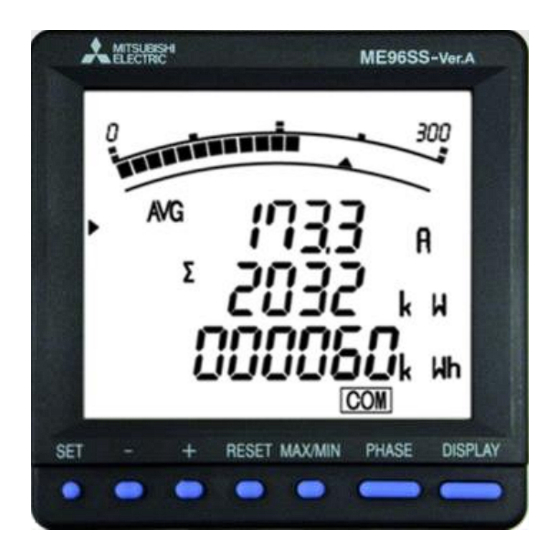
1. Display and Button Functions of Each Parts Part names ■Front view LCD with backlight Operation buttons (For details, refer to page 13.) ■Rear view (main unit) ® MODBUS RTU communication terminal ® T/R+: MODBUS RTU communication transmission terminal ® T/R-: MODBUS RTU communication transmission terminal SG: Signal Ground. - Page 12 1. Display and Button Functions of Each Parts Part names ■Rear view (Optional plug-in module: ME-4210-SS96, ME-0040C-SS96, ME-0052-SS96) Input/ output terminals (ME-4210-SS96) CH1+, CH1-: Analog output terminal Input/ output terminals (ME-0040C-SS96) CH2+, CH2-: Analog output terminal DA: CC-Link communication terminal CH3+, CH3-: Analog output terminal DB: CC-Link communication terminal CH4+, CH4-: Analog output terminal...
- Page 13 1. Display and Button Functions of Each Parts Display Note: The above display is an example for explanation. Segment Name Description LEAD status They show direction of Power Factor or Reactive Power on bar graph. They show the type of counting of Reactive Energy on Reactive Energy Display. LAG status Scale of the bar graph They show the scales of the bar graph.
- Page 14 1. Display and Button Functions of Each Parts Functions of operation buttons The operation buttons have various functions RESET MAX/MIN PHASE DISPLAY - + According to how they are pressed down. Set button Reset button Phase button Maximum/Minimum button Display button +/-button ○...
- Page 15 1. Display and Button Functions of Each Parts LEDs of the Optional plug-in module LEDs of ME-0000MT-SS96 ■ Name Function ERR. LED This indicates communication error state ME-0000MT-SS96 Normal Blink MODBUS TCP® communication error as follows was detected. ・MODBUS TCP® application protocol header was incorrect. ・Function code was incorrect(Serial only code was received), etc.
-
Page 16: Function Modes
2. Function Modes The following function modes are available for this Multi-Measuring instrument. Operation mode is displayed after auxiliary power turns on. It is then possible to switch to the desired mode. Reference Mode Description Pages P.63 to P.76 This mode is for displaying each measured value using digital numerical values and Operation bar graphs. -
Page 17: Setting
3. Setting 3.1. Setting flow To measure, it is necessary to use Setting mode to set the phase wire system, VT / direct voltage, and CT primary current. From Operation mode, move to Setting mode and then set necessary items. Factory default settings will be used for items that you do not set. - Page 18 3. Setting 3.1. Setting flow <Setting Procedure> ① ⑤After completion of setting, select ‘End’ in the setting Press simultaneously for 2 seconds to get in the setting mode. menu and press ② ⑥When the End display appears, press Select a setting menu number by once again.
- Page 19 3. Setting 3.1. Setting flow ■Setting flow when with ME-0000MT-SS96 Operation Mode Measurement Display Setting Menu Setting Menu Setting Menu Setting Menu ※1 ※2 Phase End Display Current scale wire system Save the setting. Communication setting selection Display Voltage scale Pattern VT/direct Active power...
- Page 20 3. Setting 3.1. Setting flow Setting Mode or Setting Value Confirmation Mode Setting Value ※3 Setting Menu Setting Menu Setting Menu Setting Menu Setting Menu Confirmation Menu Model + Operation time Periodic active Test Mode Alarm item ※3 energy display option code display Automatic...
- Page 21 3. Setting 3.1. Setting flow ■Setting flow when with ME-0000BU-SS96 Operation Mode Setting Menu 1 Setting Menu 3 Measurement Display Setting Menu Setting Menu CL Setting Menu 2 ※1 ※2 Present time Phase End Display MODBUS®RTU Current scale setting wire system (Month) address Save the setting.
- Page 22 3. Setting 3.1. Setting flow Setting Mode or Setting Value Confirmation Mode Setting Value ※3 Setting Menu Setting Menu Setting Menu Setting Menu Setting Menu Confirmation Menu Model + Operation time Periodic active Test Mode ※3 Alarm item Logging ID energy display option code display...
-
Page 23: Setting Menu 1: Basic Settings (Setting The Phase Wire System, Display Pattern, Vt/Direct Voltage, Ct Primary Current, Etc.)
3. Setting Basic Operations for setting Function Operation Remarks Select a set value Press Fast-forward when pressed over 1 sec. Setting item will be cared and shift to the Setting items are saved Press next item. Press Go back to the previous setting item The set value for the setting item just before DISPLAY Skip removing setting items returning is still... - Page 24 3. Setting 3.2 Setting menu 1: Basic Settings (Setting the Phase Wire System, Display Pattern, VT/Direct Voltage, CT Primary Current, etc.) (2)For other phase wire system except 3-phase 4-wire Additional display ○ ○ ○ ○ △ △ △ △ △ ○...
- Page 25 3. Setting 3.2 Setting menu 1: Basic Settings (Setting the Phase Wire System, Display Pattern, VT/Direct Voltage, CT Primary Current, etc.) Continued form the previous page (2) When using VT < > Set the secondary and primary voltages of the VT. (a)...
- Page 26 3. Setting 3.2 Setting menu 1: Basic Settings (Setting the Phase Wire System, Display Pattern, VT/Direct Voltage, CT Primary Current, etc.) Set the frequency. 50Hz 60Hz ⑤Frequency Note1.The scale value of the frequency of the bar graph display is changed, too. Note2.Scale of the analog output is changed, too.
-
Page 27: Setting Menu 2: Communication Settings (Setting The Modbus ® Rtu Communication)
3. Setting 3.3. Setting Menu 2: Communication Settings (Setting the MODBUS ® RTU communication) <Setting flow when without optional plug-in module, with ME-4210-SS96, with ME-0052-SS96 or with ME-0000BU-SS96> In the operation mode, press simultaneously for 2 seconds or more, and the following operation becomes available. -
Page 28: Setting Menu 2: Communication Settings (Setting The Cc-Link Communication)
3. Setting 3.4. Setting Menu 2: Communication Settings (Setting the CC-Link communication) <Setting flow when with ME-0040C-SS96> In the operation mode, press simultaneously for 2 seconds or more, and the following operation becomes available. Set the setting menu number to “2”. (as shown in the right figure) Setting Menu DISPLAY... - Page 29 3. Setting 3.4. Setting Menu 2: Communication Settings (Setting the CC-Link communication) When the changed above settings are enabled, set to "on." (When it is not set to “on,” the changed settings of CC-Link do not become effective.) ⑤Communication reset According to the setting flow (page 16 to 21), save the changed contents, or continue to the other setting menu.
-
Page 30: Setting Menu 2: Communication Settings (Setting The Modbus ® Tcp Communication)
3. Setting 3.5. Setting Menu 2: Communication Settings (Setting the MODBUS ® TCP communication) <Setting flow when with ME-0000MT-SS96> In the operation mode, press simultaneously for 2 seconds or more, and the following operation becomes available. DISPLAY ® ® Select either of “MODBUS TCP communication”... - Page 31 3. Setting 3.5. Setting Menu 2: Communication Settings (Setting the MODBUS ® TCP communication) Set the Default gateway existence. If the default gateway exists on the Ethernet, ④ MODBUS®TCP select “on” to communicate with other network. Default gateway existence Set the Default gateway address.
-
Page 32: Setting Menu 3: Display Settings (Setting Maximum Scale, Active Energy Measurement, And Harmonic Display, Etc.)
3. Setting 3.6. Setting Menu 3: Display Settings (Setting Maximum Scale, Active Energy Measurement, and Harmonic Display, etc.) This section shows how to set maximum scale in the bar graph, expanded counting, and harmonics display. In the operation mode, press simultaneously for 2 seconds or more, and the following operation becomes available. - Page 33 3. Setting 3.6. Setting Menu 3: Display Settings (Setting Maximum Scale, Active Energy Measurement, and Harmonic Display, etc.) Set the power factor scale. If you have not set power factor to “Display pattern”, this display will be skipped. ⑤Power factor scale -0.5 to 1 to 0.5 -0 to 1 to 0 Set the combinations of imported / exported and lag / lead for active energy and...
-
Page 34: Setting Menu 4: Lcd Settings (Setting Model Display, Version Display, Backlight, And Display Update Time)
Set the setting menu number to “4”. (as shown in the right figure) Setting menu The model can be confirmed. (This is only display, and settings cannot be changed.) (1) Middle Line Model ME96SSHA-MB (2) Lower Line Option code Blank ME-4210-SS96 ①... -
Page 35: Current Mask Function, Pulse Output, Etc.)
3. Setting Pulse and Alarm Settings (Setting Upper/Lower Limit Alarm, Motor 3.8. Setting Menu 5: Starting Current Mask Function, Pulse Output, etc.) This section shows how to set the upper/lower limit alarm, backlight flickering during alarm, motor starting current delay time, and pulse output. -
Page 36: Setting Menu 5: Pulse And Alarm Settings
3. Setting 3.8. Setting Menu 5: Pulse and Alarm Settings (Setting Upper/Lower Limit Alarm, Motor Starting Current Mask Function, Pulse Output, etc.) Set the alarm value for upper/lower limit alarm element 1. The following table shows the setting range. Setting Measuring element Setting range step(Note) - Page 37 3. Setting 3.8. Setting Menu 5: Pulse and Alarm Settings (Setting Upper/Lower Limit Alarm, Motor Starting Current Mask Function, Pulse Output, etc.) It is possible to make the backlight to flicker when an alarm is generated. ⑦ Backlight flickers (Not flicker) (Flicker) during alarms Note: When all settings for ①Alarm item 1 and ③Alarm item 2 to 4...
- Page 38 3. Setting 3.8. Setting Menu 5: Pulse and Alarm Settings (Setting Upper/Lower Limit Alarm, Motor Starting Current Mask Function, Pulse Output, etc.) Set the output function of Pulse/Alarm output 1. When the ME-4210-SS96 optional plug-in module is not installed, this display will be skipped. ⑨Pulse/Alarm Please refer to page 57 for the correspondence between Alarm output output 1...
- Page 39 3. Setting 3.8. Setting Menu 5: Pulse and Alarm Settings (Setting Upper/Lower Limit Alarm, Motor Starting Current Mask Function, Pulse Output, etc.) Set the output function of Pulse/Alarm output 2. When the ME-4210-SS96 optional plug-in module is not installed, this display will be skipped. Please refer to page 72 for the correspondence between Alarm output ⑫Plulse/Alarm and Alarm item.
-
Page 40: Setting Menu 6: Setting The Analog Output
3. Setting 3.9. Setting Menu 6: Setting the Analog Output This section shows how to set analog output. When the ME-4210-SS96 optional plug-in module is not installed, this test menu will be skipped. In the operation mode, press simultaneously for 2 seconds or more, and the following operation becomes available. Set the measurement item to be output to analog output CH1. - Page 41 3. Setting 3.9. Setting Menu 6: Setting the Analog Output Analog output CH1 detailed setting (The following setting can be made separately from the measurement items included in the display pattern.) (1)Set the current / current demand / voltage / active power / reactive power / power factor for analog output.(Setting menu 6.1.1) Output item...
- Page 42 3. Setting 3.9. Setting Menu 6: Setting the Analog Output Set analog output for when full scale is over the limit.(The same in all the CH) Setting value Description For the span value, the maximum output is +5% and the minimum output is -5%. (No limit) For the span value, the maximum output (Limited)
-
Page 43: Setting Menu 6: Setting The Logging Function
3. Setting 3.10. Setting Menu 6: Setting the Logging function This section shows how to set the logging function. When the ME-0000BU-SS96 optional plug-in module is not installed, this menu will be skipped. In the operation mode, press simultaneously for 2 seconds or more, and the following operation becomes available. RESET Set the ID number of the optional plug-in module: ME-0000BU-SS96. - Page 44 3. Setting 3.10. Setting Menu 6: Setting the Logging function Continued from the previous. Phase-wire setting: 1P2W LP01 LP02 Logging-item pattern Detailed data One-hour data Detailed data One-hour data Wh(import) Wh(import) Wh(import) Wh(import) Data 1 Data 2 varh(import LAG) Wh(export) Wh(export) varh(import LAG) varh(import LAG)
-
Page 45: Setting Menu 7: Setting Periodic Active Energy, Rolling Demand, And Digital Input/Output
3. Setting Setting Periodic Active Energy, Rolling Demand, and Digital 3.11. Setting Menu 7: Input/Output Set the periodic active energy, rolling demand, and digital input/output. In the operation mode, press simultaneously for 2 seconds or more, and the following operation becomes available. - Page 46 3. Setting Setting Periodic Active Energy, Rolling Demand, and Digital 3.11. Setting Menu 7: Input/Output Set “on or off” of the digital input/output display. When without the optional plug-in module, with ME-0000MT-SS96 or ME-0000BU-SS96, this display will be skipped. ⑤Digital input/output display (Not displayed)...
-
Page 47: Setting Menu 8:Special Settings (Setting Operation Time, Phase Display, Iec Mode)
3. Setting 8:Special Settings (Setting Operation Time, Phase Display, IEC Mode) 3.12. Setting Menu Set the operation time, phase display, IEC mode. In the operation mode, press simultaneously for 2 seconds or more, and the following operation becomes available. For more details about each function, refer to the corresponding pages. - Page 48 3. Setting 3.12. Setting Menu 8: Special Settings (Setting Operation Time, Phase Display, IEC Mode) Set the phase display. ④Phase display setting DISPLAY By the setting of this mode, the following calculation methods and signs are changed. ・Reactive energy counting method. (Refer to page 69) ・Each measurement item display during power transmission.
-
Page 49: Setting Menu Cl: Present Time Settings For Data Logging
3. Setting CL: Present Time Settings for Data Logging 3.13. Setting Menu Set the present clock time for data logging when installed the optional plug-in module: ME-0000BU-SS96. The present clock time should be set before operating the system. In the operation mode, press simultaneously for 2 seconds or more, and the following operation becomes available. - Page 50 3. Setting CL: Present Time Settings for Data Logging 3.13. Setting Menu Set “Hour”. ↔ ↔ ↔ ↔ ・・・ ⑤Present time setting Setting range: 12 AM 1 AM 2 AM 11 AM (Hour) ↔ ↔ ↔ ↔ ・・・ 12 PM 1 PM 2 PM 11 PM...
-
Page 51: Setting Value Confirmation Menus 1-9: Confirming The Settings In The Setting Menus
3. Setting 3.14. Setting Value Confirmation Menus 1-9: Confirming the Settings in the Setting Menus 1-8 and Test Mode in Setting Menu 9 ⚫ Setting Value Confirmation When is pressed for at least 2 seconds in the operation mode, the following operation becomes available. The screen transitions and operations are the same as for Setting Menus 1 to 8 and CL. -
Page 52: Initializing Related Items By Changing Settings
3. Setting 3.15. Initializing Related Items by Changing Settings When a setting value is changed, the related setting items and measurement data (maximum/minimum values) will return to the default settings. Refer to the following list. Menu 1 Menu 2 Menu 5 Menu 6 Menu 8 Setting item to be changed CT current... -
Page 53: Initializing All Settings
3. Setting 3.16. Initializing All Settings When the following operations are executed, all settings are initialized to the factory defaults. Only the settings are The measured active energy value and operating time etc. are not initialized. initialized to the defaults. For the initializing of maximum/minimum value, refer to the section 3.15(page 51). -
Page 54: Setting The Special Display Pattern P00
3. Setting 3.17. Setting the Special Display Pattern P00 Even if there is no display pattern that you like in the display patterns P01 to P13, individual setting is available by the display pattern P00. This setting is made in the setting menu 1. Explanation begins with the set “P00” in ②display pattern of the setting menu 1 (page 22). - Page 55 3. Setting 3.17.Setting the Special Display Pattern P00 Continued form the previous page (5) Set the display of the display 4-2. Select “yES” by and press When you do not want to display the display 2, select “no” and press (6)...
-
Page 56: Examples Of Simple Settings
3. Setting 3.18. Examples of Simple Settings The following shows a simple setting example. ME96SSHA-MB(Not optional plug-in unit) ■Setting Example Model: Phase wire system : 3-phase 4-wire A, V, W, PF Measuring element : Input Voltage :220/380V CT primary current : 200A... - Page 57 3. Setting 3.18. Examples of Simple Settings...
-
Page 58: Using Test Mode
4. Using Test Mode Test mode includes functions that can be used for start-up of equipment. The following table shows what can be done in the test mode. Test menu Description For models with a communication function, it is possible to monitor fixed numerical Communication test data without measurement (voltage/current) input. -
Page 59: Test Menu 1: Communication Test
4. Using Test Mode 4.1. Test Menu 1: Communication Test In the setting value confirmation mode, when the menu number is set to "9", you will enter the test mode. Set the test menu number to "1". (as shown in the right figure) Test menu Execute communication test operation. -
Page 60: Test Menu 2: Alarm Output/Digital Output Operation Test
4. Using Test Mode 4.2. Test Menu 2: Alarm Output/Digital Output Operation Test The following operations are available in the test mode. ・When the ME-4210-SS96 or ME-0052-SS96 optional plug-in module is not installed, this test menu will be skipped. ・When ⑨Pulse/Alarm output 1(Setting Menu 5) and ⑫Pulse/Alarm output 2(Setting Menu 5) is not set to "AL", this test menu will be skipped.(ME-4210-SS96) DISPLAY Execute the alarm output/digital output CH1 operation test. -
Page 61: Test Menu 3: Zero Span Adjustment For Analog Output
4. Using Test Mode 4.3. Test Menu 3: Zero Span Adjustment for Analog Output The following operations are available in the test mode. When the ME-4210-SS96 optional plug-in module is not installed, this test menu will be skipped. DISPLAY Execute zero adjustment for analog output CH1. Possible setting range : -50 to ±0 to +50 Adjustment is possible up to about ±0.3mA ■... -
Page 62: Test Menu 4: Analog Output Operation Test
4. Using Test Mode 4.4. Test Menu 4: Analog Output Operation Test The following operations are available in the test mode. When the ME-4210-SS96 optional plug-in module is not installed, this test menu will be skipped. DISPLAY Execute the operation test for analog output CH1. (Input is not necessary.) Output Specification Output 4-20mA... -
Page 63: Test Menu 5: Pulse Output Operation Test
4. Using Test Mode 4.5. Test Menu 5: Pulse Output Operation Test The following operations are available in the test mode. ・When the ME-4210-SS96 optional plug-in module is not installed, this test menu will be skipped. ・When ⑨Pulse/Alarm output 1(Setting Menu 5) and ⑫Pulse/Alarm output 2(Setting Menu 5) is not set to "PULSE", this test menu will be skipped.(ME-4210-SS96) DISPLAY Execute the operation test for pulse output CH1. -
Page 64: Operation
5. Operation 5.1. Basic Operation Display items and the order differ depending on the phase wire The following explains basic usages during operation. method setting display pattern settings and additional screen. ⚫ Switch display For more information about detailed display patterns, refer to pages 77 and 78. -
Page 65: Bar Graph Display
5. Operation 5.1. Basic Operation ⚫ Bar graph display Bar graph displays the measurement element indicated with “ ” or “ ”. (Example) Lower element (V) (Example) PF displayed on displayed on bar graph bar graph ⚫ Switching measurement factors displayed on bar graphs Press the button to switch. -
Page 66: Cyclic Display
5. Operation 5.1. Basic Operation ⚫ Cyclic Display In cyclic display, display and phases automatically change at every 5 seconds. When is pressed for about 2 seconds, the cyclic display appears. DISPLAY When is pressed for about 2 seconds, the cyclic phase appears. By pressing any other buttons except , cyclic display mode ends. - Page 67 5. Operation 5.1. Basic Operation ⚫ Harmonics display (Continued from previous page) ■Switching degree / phase (Phase wire System: 3-phase 4-wire) Press the button to switch the degree. Press to switch phases. Harmonic current Harmonic current Harmonic voltage (phase N) Current total phase 1 Current total phase N Voltage total phase 1N...
-
Page 68: Maximum Value And Minimum Value Display
5. Operation 5.1. Basic Operation ⚫ Maximum value and minimum value display For the maximum / minimum value display screen, the maximum value, current value, and minimum value for each measurement item are displayed on one screen. However, for harmonics only the following maximum values are displayed. Harmonic current: Total, 1st to 31st (only odd number) effective values for where the phase was largest for each phase. -
Page 69: Active Energy / Reactive Energy / Apparent Energy Display
5. Operation 5.1. Basic Operation ⚫ Active Energy / Reactive Energy / Apparent Energy Display ■ Display format The following table shows the display format of active energy / reactive energy / apparent energy based on the total load. α: 1 1-phase 2-wire 2 1-phase 3-wire α... -
Page 70: Reactive Energy Counting Method (2 Quadrant Counting / 4 Quadrant Counting)
5. Operation 5.1. Basic Operation ⚫ Reactive energy counting method (2 quadrant counting / 4 quadrant counting) There are the following two types of quadrants for counting reactive energy. -var -var -W +W -W +W +var +var Counting Description method It is counting (Imported lag), (Exported lead),(Imported lead) and (Exported lag) respectively as division of one. -
Page 71: Demand Time And Demand Value Of Current Demand
5. Operation 5.1. Basic Operation ⚫ Demand time and demand value of current demand The demand time (t ) is the time until the measurement display value (I ) displays 95% of the input (I) when a certain constant input (I) is given. To display 100% of the input (I), about three times more than the time (t ) is needed. -
Page 72: Usage According To Purpose (Alarm, Periodic Active Energy, Rolling Demand, Operating Time, Password, Etc.)
5. Operation 5.2. Usage According to Purpose (Alarm, Periodic Active Energy, Rolling Demand, Operating Time, Password, etc.) The following explains usage according to the purpose during operation. ⚫ Display and operation of the upper/lower limit alarm When the value exceeds the upper or lower limit setting value set in advance, the display flickers and alarm can be output. (For more information about how to set the upper/lower limit alarm, refer to page 34 and after.) -
Page 73: Canceling The Upper/Lower Limit Alarm
5. Operation 5.2 Usage According to Purpose (Alarm, Periodic Active Energy, Rolling Demand, Operating Time, Password, etc.) ⚫ Canceling the upper/lower limit alarm The upper and lower limit alarms can be The alarm cancellation method differs depending on the setting for alarm reset. cancelled also via communication. -
Page 74: Display And Calculation Of Rolling Demand
5. Operation 5.2 Usage According to Purpose (Alarm, Periodic Active Energy, Rolling Demand, Operating Time, Password, etc.) ⚫ Display and calculation of rolling demand The rolling demand is the value obtained by dividing the active energy/reactive energy/apparent energy (*1) in a specified time (interval) by the length of the interval. -
Page 75: Adjusting Rolling Demand Time
5. Operation 5.2 Usage According to Purpose (Alarm, Periodic Active Energy, Rolling Demand, Operating Time, Password, etc.) ⚫ Adjusting rolling demand time Showing the rolling demand on the display and then holding down the buttons at the same time for 2 seconds or more allows adjustment of the rolling demand time. -
Page 76: Display And Operation Of Digital Input/Output Status
5. Operation 5.2 Usage According to Purpose (Alarm, Periodic Active Energy, Rolling Demand, Operating Time, Password, etc.) ⚫ Display and operation of digital input/output status The digital status can be displayed by inputting the switching signal of the breaker and the alarm signal of the over current relay to the digital input (DI) terminal. -
Page 77: Password Protection Setting
5. Operation 5.2 Usage According to Purpose (Alarm, Periodic Active Energy, Rolling Demand, Operating Time, Password, etc.) ⚫ Password protection setting In the operation mode, after pressing simultaneously for 2 seconds or more, the password input RESET display will be displayed. It is possible to set the password protection if you enter the password. Default password is “0000”. -
Page 78: Other
6. Other 6.1. Display Pattern Contents When the display pattern in the Setting menu 1 and the additional screen in the Setting menus 3, 7, and 8 are set, pressing changes the screens shown in the table below from the left to the right. [For 3-phase 4-wire] Additional display (Set in the setting menus 3, 7, 8) Screen set by display pattern... - Page 79 6. Other 6.1 Display Pattern Contents [For others except 3-phase 4-wire] Screen set by display pattern Additional display (Set in the setting menus 3, 7, 8) Display No.7 No.8 No.9 No.10 No.11 No.12 No.13 No.14 No.15 No.16 No.17 No.18 No.19 No.20 No.21 No.22...
-
Page 80: Maximum Scale Value
6. Other 6.2. Maximum Scale Value Settable primary voltage, primary current, and standard maximum scale value are shown in the tables below. ● Specific power value for scale calculation ● Maximum scale value of each item Phase line Specific power Rated voltage type Secondary... -
Page 81: Possible Setting Range For Maximum Scale
6. Other 6.3. Possible Setting Range for Maximum Scale The maximum scale of current can be selected from about 40% to 120% of rating, and maximum scale of voltage can be selected from about 20% to 250% of rating, and maximum scale of active power and reactive power can be selected from about 20% to 120% of rating. - Page 82 6. Other 6.3 Possible Setting Range for Maximum Scale ■Voltage maximum scale value Possible setting range:-18 STEP to +10STEP of the standard maximum scale value. Example: When the standard maximum scale value is 100V, the value is from 20V to 320V. Voltage maximum scale value (1/3) Voltage maximum scale value (2/3) Voltage maximum scale value (3/3)
- Page 83 6. Other 6.3 Possible Setting Range for Maximum Scale ■Maximum scale value for active power / reactive power Possible setting range:-18 STEP to +3STEP of the rating Example: When the rating is 1000W, the value is from 200W to 1600W. Maximum scale value Maximum scale value Maximum scale value...
-
Page 84: Measurement Items And Correspondence Between Display And Output
6. Other 6.4. Measurement Items and Correspondence between Display and Output The table below shows the measurement items and correspondence between display and output. ○:Data can be displayed or output -:Data cannot be displayed or output Item measurement display Analog Pulse 3-phase 3-phase 3-wire(2CT) -
Page 85: Measurement Characteristic
6. Other 6.5. Measurement Characteristic ■Metering actions in other than operation mode Status Measurement Display Analog output Pulse output Alarm contact point Several seconds Output over about No measurement No display Opened No output just after turning on 100% may be made the auxiliary power until internal voltage supply... -
Page 86: Troubleshooting
6. Other 6.6. Troubleshooting In the case of abnormal noise, odor, smoke, or heat generation from this instrument, turn it off at once. Check the followings before you ask for repair. Condition Possible cause Solution Auxiliary power supply is not impressed on The display is not lit. - Page 87 6. Other 6.6 Troubleshooting Condition Possible cause Solution MODBUS RTU® communication error as Review the communication setting, the COM in the LCD screen is follows was detected. function code and the register address and so blinking. (Appears for 0.25sec. / ・Communication setting(Slave address, baud Disappears for 0.25sec.) rate, stop bit and parity) was incorrect.
-
Page 88: Installation 1. Dimensions
Installation 1. Dimensions ME96SSHA-MB Optional Plug-in Module ME-4210-SS96 ME-0040C-SS96 ME-0052-SS96... - Page 89 Installation 1. Dimensions Optional Plug-in Module ME-0000MT-SS96 Optional Plug-in Module ME-0000BU-SS96...
-
Page 90: Installation 2. Mounting
Installation 2. Mounting 1 Dimensions of mounting holes The drilling dimensions of the panel are as shown in the right figure. The product can be installed to a panel having a thickness of 1.6 to 4.0 mm. 2 Mounting position The contrast of the LCD changes depending on the angle at which it is viewed. -
Page 91: Installation 3. Wiring
Installation 3. Wiring 1 Applicable electric wire specifications The following table shows applicable electric wire sizes Tightening Section Screw type Specification of wire used torques Terminal of main unit. ・Use crimping terminals: AWG26 to 14 (Connectable 2 wires) (Auxiliary power, Voltage input, Applicable crimping terminals: Current input,... - Page 92 Installation 3. Wiring Do not work with live wires Do not connect terminal and RJ-45 connector with live wires. insert and remove SD CRAD with live wires. Do not It may cause electric shock, burns, device burn out, or fire. It is recommended that a protection fuse be used for VT and the auxiliary power source.
-
Page 93: Installation 4. Wiring Diagram
Installation 4. Wiring Diagram Rating voltage for every phase wire system Phase wire type Type Rating voltage Figure 3-phase 4-wire type STAR max AC277V(L-N)/480V(L-L) Figure 1 DELTA max AC220V(L-L) Figure 2 3-phase 3-wire type STAR max AC440V(L-L) Figure 3 1-phase 3-wire type ―... - Page 94 Installation 4. Wiring Diagram 3-phase 4-wire type: Direct input ①Auxiliary power supply AC100 to 240V or DC100 to 240V. ②Fuses 0.5A ③Some MODBUS®RTU equipment doesn’t have SG. In this case, the wiring between SG is unnecessary. Note 1: For low voltage circuits, grounding the secondary side of VT and CT is not t necessary. 3-phase 4-wire type: With VT ①Auxiliary power supply AC100 to 240V or DC100 to 240V.
- Page 95 Installation 4. Wiring Diagram 3-phase 3-wire(2CT) type: Direct input ①Auxiliary power supply AC100 to 240V or DC100 to 240V. ②Fuses 0.5A ③Some MODBUS®RTU equipment doesn’t have SG. In this case, the wiring between SG is unnecessary. Note 1: For low voltage circuits, grounding the secondary side of VT and CT is not t necessary. Note 2: Do not connect to NC terminal.
- Page 96 Installation 4. Wiring Diagram 1-phase 3-wire type ①Auxiliary power supply AC100 to 240V or DC100 to 240V. ②Fuses 0.5A ③Some MODBUS®RTU equipment doesn’t have SG. In this case, the wiring between SG is unnecessary. Note 1: For low voltage circuits, grounding the secondary side of CT is not t necessary. 1-phase 2-wire type: With VT ①Auxiliary power supply AC100 to 240V or DC100 to 240V.
- Page 97 Installation 4. Wiring Diagram Optional Plug-in Module: ME-4210-SS96 Optional Plug-in Module: ME-0040C-SS96 Optional Plug-in Module: ME-0052-SS96...
- Page 98 Installation 4. Wiring Diagram Optional Plug-in Module: ME-0000MT-SS96 Optional Plug-in Module: ME-0000BU-SS96...
- Page 99 Installation 4. Wiring Diagram Note for Input 1. The voltage input terminals for 3-phase 3-wire are different from those for others. 2. If the polarity for VT and CT are wrong, the measurement cannot be executed correctly. 3. Do not connect wires to the NC terminals. Note 4.
- Page 100 Installation 4. Wiring Diagram Note for MODBUS®TCP 1. In 100Mbps communication by the 100BASE-TX connection, a communication error may occur under the influence of high frequency noise from devices other than this device in the installation environment. Take the following action to prevent the influence of high frequency noise in the construction of a network system.
-
Page 101: Installation 5. How To Insert And Eject The Sd Memory Card (Me-0000Bu-Ss96)
Slide the SD memory card straight into the slot until it clicks into place. ・Make sure to use the SD memory card manufactured by Mitsubishi Electric Corporation (Model EMU4-SD2GB). Using the other types of the SD memory card may cause the trouble such as data CAUTION destruction of the memory card or system failure. -
Page 102: Specifications
Specifications 1. Specification Type ME96SSHA-MB 3-PHASE 4-WIRE, 3-PHASE 3-WIRE(3CT, 2CT), 1-PHASE 3-WIRE, 1-PHASE 2-WIRE (common) Phase wire system AC5A, AC1A (common) Current 3-PHASE 4-WIRE:max AC277/480V 3-PHASE 3-WIRE:(DELTA)max AC220V, (STAR)max AC440V Rating Voltage 1-PHASE 3-WIRE:max AC220/440V 1-PHASE 2-WIRE:(DELTA)max AC220V, (STAR)max AC440V... -
Page 103: Applicable Standards
Specifications 2. Applicable Standards Electromagnetic Compatibility Emissions EN61326-1/CISPR 11, Radiated Emission FCC Part15 Subpart B Class A EN61326-1/CISPR 11 Conducted Emission FCC Part15 Subpart B Class A Harmonics Measurement EN61000-3-2 Flicker Meter Measurement EN61000-3-3 Immunity Electrostatic discharge Immunity EN61326-1/EN61000-4-2 Radio Frequency Electromagnetic field Immunity EN61326-1/EN61000-4-3 Electrical Fast Transient/Burst Immunity EN61326-1/EN61000-4-4... -
Page 104: Specifications Of Modbus ® Tcp Communication
It is the logging period when data is output in maximum volume. *3. Make sure to use the SD memory card manufactured by Mitsubishi Electric Corporation (Model EMU4-SD2GB). Using the other types of the SD memory card may cause the trouble such as data destruction of the memory card or system failure. -
Page 105: Setting Table (Factory Settings And Customer Setting Note)
Specifications 7. Setting Table (Factory Settings and Customer Setting Note) Setting menu No. Setting items Initial content Memo Phase wire system 3P4(3-phase 4-wire) Display pattern ― 1.2.1 Pattern P00 VT/direct selection no(No VT) 1.3.1 Direct voltage 220/380V ― 1.3.2 VT secondary voltage ―... - Page 106 Specifications 7. Setting Table (Factory Settings and Customer Setting Note) Setting menu No. Setting items Initial content Memo Analog output CH1: output item 5A(CT primary 6.1.1 Detailed setting (1) current) ― 6.1.2 Detailed setting (2) Analog output CH2: output item (L-N) 6.2.1 Detailed setting (1)
-
Page 107: Appendix
Appendix 1. Calculation methods of ME96SS (for 3 phase unbalanced system with neutral) Item Normal mode IEC mode Remark R.m.s current for phase p − R.m.s neutral current Lp-N r.m.s voltage Lp-Lg r.m.s voltage Active power for phase p Apparent power for phase p Refer to page 69 for the sign. -
Page 108: Optional Part (Available Part)
2. Optional part (Available part) ■ SD memory card Item Specifications Model EMU4-SD2GB Amount of memory Mass [Note] Unit: mm... - Page 109 Vte. Agua Santa 4211 Casilla 30-D (P.O. Box) Vina del Mar, Chile +56-32-2-320-600 Mitsubishi Electric Automation (China) Ltd. Mitsubishi Electric Automation Building, No.1386 Hongqiao Road, Shanghai, China 200336 +86-21-2322-3030 Mitsubishi Electric Automation (China) Ltd. 5/F,ONE INDIGO,20 Jiuxianqiao Road Chaoyang District,Beijing, China 100016...
Need help?
Do you have a question about the ME96SSHA-MB and is the answer not in the manual?
Questions and answers