Table of Contents
Advertisement
Quick Links
Advertisement
Table of Contents

Subscribe to Our Youtube Channel
Related Manuals for Mitsubishi Electric ME96SSE-MB


Summary of Contents for Mitsubishi Electric ME96SSE-MB
- Page 1 MITSUBISHI Electronic Multi-Measuring Instrument Types ME96SSE-MB User's Manual: Detailed Edition ● Before operating the instrument, you should first read thoroughly this operation manual for safe operation and optimized performance of the product. Deliver this user's manual to the end use...
-
Page 2: Check On Your Delivery
Check on your delivery Check the following point as soon as you receive Mitsubishi Electronic Multi-Measuring Instrument. Parts name Quantity Specifications User’s Manual (Simplified) A3 size Attachment lug (with screw) About the optional plug-in module sold separately This product cannot be installed the optional plug-in module. Please use a combination of other classes (ME96SSH-MB, ME96SSR-MB) and the optional plug-in module, if analog output, CC-Link communication, or contact input and output etc is required. -
Page 3: Features
Features This instrument measures the load status by inputting the secondary side of the VT and CT, and displays various measurement values. The password protection setting avoids undesired change of settings or deletion of measured data. The instruments with transmission functions (MODBUS ®... -
Page 4: Table Of Contents
Table of Contents Check on your delivery ····························································································································································································1 About the optional plug-in module sold separately ··································································································································· 1 Features ·························································································································································································································· 2 Table of Contents ······································································································································································································· 3 Safety precaution ······································································································································································································· 5 EMC Directive Instruction ······················································································································································································ 8 Precautions for KC mark ························································································································································································ 8 Instructions for Handling 1.... - Page 5 Table of Contents 5.2 Usage According to Purpose (Alarm, Operating Time, Password, etc.) Display and operation of the upper/lower limit alarm ············································································································· 42 Canceling the upper/lower limit alarm ············································································································································ 43 Stopping backlight flickering caused by upper/lower limit alarm generation ······························································ 43 ...
-
Page 6: Safety Precaution
Safety Precaution (Always read these instructions before using this equipment) For personnel and product safety please read the contents of these operating instructions carefully before using. Make sure that the end users read this manual and then keep the manual in a safe place for future reference. - Page 7 Safety Precaution ■Others ® MODBUS T/R+,T/R-,Ter terminals maxDC35V communication Do not drop this instrument from high place. If you drop it and the display is cracked, do not touch the liquid crystal or get it in your mouth. If the liquid crystal is touched, wash it away at once.
- Page 8 Safety Precaution ■ Storage conditions To store this instrument, turn off the power and remove wires, and put it in a plastic bag. For long-time storage, store at the following places. Failure to follow the instruction may cause a failure and reduced life of the instrument.
-
Page 9: Emc Directive Instruction
(Class A). Do not use the product in a residential area. ■ Applicant for KC mark : MITSUBISHI ELECTRIC AUTOMATION KOREA CO.,LTD ■ Manufacturer : MITSUBISHI ELECTRIC CORPORATION Note 1: This is the notification for the KC mark (Korea Certification) -
Page 10: 1. Display And Button Functions Of Each Part
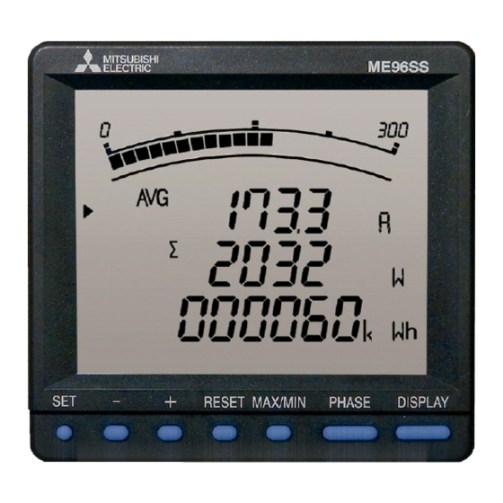
1. Display and Button Functions of Each Parts Part names ■Front view LCD with backlight Operation buttons (For details, refer to page 11.) ® MODBUS RTU communication terminal ® T/R+: MODBUS RTU communication transmission terminal ® T/R-: MODBUS RTU communication transmission terminal ■Rear view (main unit) Ter: Termination terminal... - Page 11 1. Display and Button Functions of Each Parts Display Note: The above display is an example for explanation. Segment Name Description LEAD status They show direction of Power Factor on bar graph. LAG status Scale of the bar graph They show the scales of the bar graph. Under scale input Turns on when measuring values fall below the minimum scale.
- Page 12 1. Display and Button Functions of Each Parts Functions of operation buttons The operation button have various functions - + RESET MAX/MIN PHASE DISPLAY According to how they are pressed down. Set button Reset button Phase button +/-button Maximum/Minimum button Display button ○...
-
Page 13: 2. Function Modes
2.Function Modes The following function modes are available for this Multi-Measuring instrument. Operation mode is displayed after auxiliary power turns on. It is then possible to switch to the desired mode. Reference Mode Description Pages This mode is for displaying each measured value using digital numerical values and Operation P.37 to P.44 bar graphs. -
Page 14: 3.1 Setting Flow
3. Setting 3.1 Setting flow To measure, it is necessary to use Setting mode to set the phase wire system, VT / direct voltage, and CT primary current. From Operation mode, move to Setting mode and then set necessary items. Factory default settings will be used for items that you do not set. - Page 15 3. Setting 3.1 Setting flow <Setting Procedure> ① ⑤After completion of setting, select ‘End’ in the setting Press simultaneously for 2 RESET seconds to get in the setting mode. menu and press ② ⑥When the End display appears, press Select a setting menu number by once again.
-
Page 16: 3.2 Setting Menu 1: Basic Settings
3. Setting ■ Basic Operations for setting Function Operation Remarks Select a set value Press Fast-forward when pressed over 1 sec. + - Setting item will be cared and shift to the next Setting items are saved Press item. Press Go back to the previous setting item The set value for the setting item just before DISPLAY... - Page 17 3. Setting 3.2 Setting menu 1: Basic Settings (Setting the Phase Wire System, Display Pattern, VT/Direct Voltage, CT Primary Current, etc.) (2)For other phase wire system except 3-phase 4-wire Additional display ○ ○ ○ ○ △ ○ ○ ○ ○ ○...
- Page 18 3.Setting 3.2 Setting menu 1: Basic Settings (Setting the Phase Wire System, Display Pattern, VT/Direct Voltage, CT Primary Current, etc.) Continued form the previous page (2) When using VT < > Set the secondary and primary voltages of the VT. (a)...
- Page 19 3.Setting 3.2 Setting menu 1: Basic Settings (Setting the Phase Wire System, Display Pattern, VT/Direct Voltage, CT Primary Current, etc.) Set the frequency. 50Hz 60Hz ⑤Frequency Note1.The scale value of the frequency of the bar graph display is changed, too. Note2.Scale of the analog output is changed, too.
-
Page 20: Rtu Communication)
3. Setting ® 3.3 Setting Menu 2: Communication Settings (Setting the MODBUS RTU communication) RESET In the operation mode, press simultaneously for 2 seconds or more, and the following operation becomes available. Set the setting menu number to “2”. (as shown in the right figure) Setting Menu DISPLAY ®... -
Page 21: 3.4 Setting Menu 3: Display Settings
3. Setting 3.4 Setting Menu 3: Display Settings (Setting Maximum Scale) This section shows how to set maximum scale of current, voltage, active power and power factor in the bar graph. In the operation mode, press simultaneously for 2 seconds or more, and the following operation RESET becomes available. - Page 22 3. Setting 3.4 Setting Menu 3: Display Settings (Setting Maximum Scale, Active Energy Measurement, and Harmonic Display, etc.) Set the power factor scale. If you have not set power factor to “Display pattern”, this display will be skipped. ④Power factor scale -0.5 to 1 to 0.5 -0 to 1 to 0 According to the setting flow diagram (page 14), save the changed...
- Page 23 DISPLAY The model can be confirmed. (This is only display, and settings cannot be changed.) ① Model + option code Model ME96SSE-MB DISPLAY The product version can be checked. (The product version is displayed, but cannot be changed.) ②Version display DISPLAY The backlight brightness can be adjusted.
-
Page 24: Function)
3. Setting 3.6 Setting Menu 5: Alarm Settings (Setting Upper/Lower Limit Alarm, Motor Starting Current Mask Function.) This section shows how to set the upper/lower limit alarm, backlight flickering during alarm, motor starting current delay time, and pulse output. In the operation mode, press simultaneously for 2 seconds or more, and the following operation becomes RESET available. - Page 25 3. Setting 3.6 Setting Menu 5: Alarm Settings (Setting Upper/Lower Limit Alarm, Motor Starting Current Mask Function.) Set the alarm value for upper/lower limit alarm element 1. The following table shows the setting range. Setting Measuring element Setting range step(Note) 5 to 100 to 120(%)...
- Page 26 3. Setting 3.6 Setting Menu 5: Alarm Settings (Setting Upper/Lower Limit Alarm, Motor Starting Current Mask Function.) It is possible to make the backlight to flicker when an alarm is generated. oFF on ⑦ Backlight flickers (Not flicker) (Flicker) during alarms Note: When all settings for ①Alarm item 1 and ③Alarm item 2 to 4 are set to "non,"...
-
Page 27: 3.7 Setting Menu 6:No Settings
3. Setting Setting Menu 6:No Settings Since there is no corresponding function, this setting item is not displayed. In the operation mode, press simultaneously for 2 seconds or more, and the following screen is displayed. RESET There is no settings if you set the setup menu 6. Setting menu Setting Menu 7:No Settings... -
Page 28: 3.9 Setting Menu 8: Special Settings (Setting Operating Time, Phase Display, Iec Mode)
3.Setting 3.9 Setting Menu 8:Special Settings (Setting Operation Time, Phase Display, IEC Mode) Set the operation time, phase display, IEC mode. In the operation mode, press simultaneously for 2 seconds or more, and the following operation becomes RESET available. For more details about each function, refer to the corresponding pages. - Page 29 3.Setting 3.9 Setting Menu 8:Special Settings (Setting Operation Time, Phase Display, IEC Mode) Set the phase display. ④Phase display setting DISPLAY Set the mode for reactive power/ power factor, etc arithmetic expression and code to normal or IEC. ⑤Set IEC mode (Normal mode)...
-
Page 30: Test Mode In Setting Menu 9
3.Setting 3.10 Setting Value Confirmation Menus 1-9: Confirming the Settings in the Setting Menus 1-8 and Test Mode in Setting Menu 9 Setting Value Confirmation When is pressed for at least 2 seconds in the operation mode, the following operation becomes available. The screen transitions and operations are the same as for Setting Menus 1 to 8. -
Page 31: 3.11 Initializing Related Items By Changing Settings
3. Setting 3.11 Initializing Related Items by Changing Settings When a setting value is changed, the related setting items and measurement data (maximum/minimum values) will return to the default settings. Refer to the following list. Menu 1 Menu 5 Menu 8 Setting item to be changed CT current Initialized item... -
Page 32: 3.13 Setting The Special Display Patten P00
3. Setting 3.13 Setting the Special Display Pattern P00 Even if there is no display pattern that you like in the display patterns P01 to P05, individual setting is available by the display pattern P00. This setting is made in the setting menu 1. Explanation begins with the set “P00” in ②display pattern of the setting menu 1 (page 15). - Page 33 3. Setting 3.13 Setting the Special Display Pattern P00 Continued form the previous page (5) Set the display of the display 4-2. Select “yES” by and press + - When you do not want to display the display 2, select “no” and press (6)...
-
Page 34: 3.14 Examples Of Simple Settings
3.Setting 3.14 Examples of Simple Settings The following shows a simple setting example. ■Setting Example Model: ME96SSE-MB Phase wire system : 3-phase 4-wire Measuring element : A, V, W, PF Input Voltage :220/380V CT primary current : 200A CT Secondary current:5A... - Page 35 3.Setting 3.14 Examples of Simple Settings ® MODBUS The factory default setting is "1," so just press SET. address ® MODBUS The factory default setting is "19.2kbps," so just press SET. baud rates ® MODBUS The factory default setting is "EVEn(even)," so just press SET . parity ®...
-
Page 36: 4. Using Test Mode
4. Using Test Mode Test mode includes functions that can be used for start-up of equipment. The following table shows what can be done in the test mode. Test menu Description For models with a communication function, it is possible to monitor fixed numerical 1.Communication test data without measurement (voltage/current) input. -
Page 37: 4.1 Test Menu 1: Communication Test
4. Using Test Mode 4.1 Test Menu 1: Communication Test In the setting value confirmation mode, when the menu number is set to "9", you will enter the test mode. Set the test menu number to "1". (as shown in the right figure) Test menu Execute communication test operation. -
Page 38: Switch Display
5. Operation Basic Operation The following explains basic usages during operation. Switch display Display items and the order differ depending on the phase wire method setting display pattern settings and additional screen. By pressing , the measurement DISPLAY For more information about detailed display patterns, refer to pages 45. -
Page 39: Bar Graph Display
5. Operation 5.1 Basic Operation Bar graph display Bar graph displays the measurement element indicated with “ ” or “ ”. (Example) Lower element (V) (Example) PF displayed on displayed on bar graph bar graph Switching measurement factors displayed on bar graphs Press the button to switch. -
Page 40: Cyclic Display
5. Operation Basic Operation Cyclic Display In cyclic display, display and phases automatically change at every 5 seconds. When is pressed for about 2 seconds, the cyclic display appears. DISPLAY When is pressed for about 2 seconds, the cyclic phase appears. PHASE By pressing any other buttons except , cyclic display mode ends. -
Page 41: Maximum Value And Minimum Value Display
5. Operation Basic Operation Maximum value and minimum value display For the maximum / minimum value display screen, the maximum value, current value, and minimum value for each measurement item are displayed on one screen. ■ Example Display <Example of current> The bar graph turns on only between the maximum value and minimum value. -
Page 42: Active Energy Display
5.Operation 5.1 Basic Operation Active Energy Display Display format ■ The following table shows the display format of active energy based on the total load. α x (VT primary voltage) x (CT primary current) α: 1 1-phase 2-wire Total load power[kW] = 2 1-phase 3-wire 1000 √... -
Page 43: 5.2 Usage According To Purpose (Alarm, Operating Time, Password, Etc.)
5.Operation 5.2 Usage According to Purpose (Alarm, Operating Time, Password, etc.) The following explains usage according to the purpose during operation. Display and operation of the upper/lower limit alarm When the value exceeds the upper or lower limit setting value set in advance, the display flickers and alarm can be output. (For more information about how to set the upper/lower limit alarm, refer to page 23 and after.) -
Page 44: Canceling The Upper/Lower Limit Alarm
5.Operation 5.2 Usage According to Purpose (Alarm, Operating Time, Password, etc.) Canceling the upper/lower limit alarm The alarm cancellation method differs depending on the setting for alarm reset. The upper and lower limit alarms can be cancelled also via communication. Alarm cancel method Cancelation method When the measurement value is below the upper/lower limit set value, the alarm is... -
Page 45: Preventing Maximum Value Update By Motor Starting Current
5.Operation 5.2 Usage According to Purpose (Alarm, Operating Time, Password, etc.) Preventing maximum value update by motor starting current When the motor current is monitored, use the motor starting current delay function to prevent maximum value update and alarm generation for the current, active power, reactive power, apparent Power ,and power factor due to the motor starting current. -
Page 46: 6.1 Display Pattern Contents
6.Other Display Pattern Contents When the display pattern in the Setting menu 1 and the additional screen in the Setting menu 8 are set, pressing changes the screens shown in the table below from the left to the right. DISPLAY 【For 3-phase4-wire】... -
Page 47: 6.2 Maximum Scale Value
6. Other 6.2 Maximum Scale Value Settable primary voltage, primary current, and standard maximum scale value are shown in the tables below. ● Specific power value for scale calculation ● Maximum scale value of each item Phase line Specific power Measurement element Maximum scale value Rated voltage... -
Page 48: 6.3 Possible Setting Range For Maximum Scale
6. Other 6.3 Possible Setting Range for Maximum Scale The maximum scale of current can be selected from about 40% to 120% of rating, and maximum scale of voltage can be selected from about 20% to 250% of rating, and maximum scale of active power can be selected from about 20% to 120% of rating. - Page 49 6. Other 6.3 Possible Setting Range for Maximum Scale ■Voltage maximum scale value Possible setting range:-18 STEP to +10STEP of the standard maximum scale value. Example: When the standard maximum scale value is 100V, the value is from 20V to 320V. Voltage maximum scale value (1/3) Voltage maximum scale value (2/3) Voltage maximum scale value (3/3)
- Page 50 6. Other 6.3 Possible Setting Range for Maximum Scale ■Maximum scale value for active power Possible setting range:-18 STEP to +3STEP of the rating Example: When the rating is 1000W, the value is from 200W to 1600W. Maximum scale value Maximum scale value Maximum scale value Maximum scale value Maximum scale value...
-
Page 51: 6.4 Measurement Items And Correspondence Between Display And Output
6. Other 6.4 Measurement Items and Correspondence between Display and Output The table below shows the measurement items and correspondence between display and output. ○:Data can be displayed or output Blank:Data cannot be displayed or output Item measurement display 3-phase 3-wire(3CT) munic Measurement item 3-phase 3-wire(2CT) -
Page 52: 6.5 Measurement Characteristic
6.Other 6.5 Measurement Characteristic ■Metering actions in other than operation mode Status Measurement Display Several seconds just No measurement No display after turning on the auxiliary power supply (Backlight is lit, and LCD is not lit.) Setting mode, Same actions No display of Set value confirmation as in operation... -
Page 53: 6.6 Troubleshooting
6.Other 6.6 Troubleshooting In the case of abnormal noise, odor, smoke, or heat generation from this instrument, turn it off at once. Check the followings before you ask for repair. Condition Possible cause Solution Auxiliary power supply is not impressed on The display is not lit. -
Page 54: 1. Dimensions
Installation 1. Dimensions - 53 -... -
Page 55: 2. Mounting
Installation 2. Mounting 1 Dimensions of mounting holes The drilling dimensions of the panel are as shown in the right figure. The product can be installed to a panel having a thickness of 1.6 to 4.0 mm. 2 Mounting position The contrast of the LCD changes depending on the angle at which it is viewed. -
Page 56: 3. Wiring
Installation 3. Wiring 1 Applicable electric wire The following table shows applicable electric wire sizes . (Wire coating stripping length:10 to 11mm) Screw Section Specification of wire used type Auxiliary power, voltage Single wire, Stranded wire: AWG24 to 14 ® (Stranded wire is bar terminal can be used in combination.) input, MODBUS communication terminal... - Page 57 Installation 3. Wiring Do not work with hot-line jobs Do not connect hot-line jobs. It may cause electric shock, burns, device burn out, or fire. It is recommended that a protection fuse be used for VT and the auxiliary power source. Do not open the secondary side of the CT circuit Connect the CT secondary side signal correctly to the terminal for CT connection.
-
Page 58: 4. Wiring Diagram
Installation 4. Wiring Diagram Rating voltage for every phase wire system Phase wire type Type Rating voltage Figure 3-phase 4-wire type STAR max AC277V(L-N)/480V(L-L) Figure 1 DELTA max AC220V(L-L) Figure 2 3-phase 3-wire type STAR max AC440V(L-L) Figure 3 ― 1-phase 3-wire type max AC220V(L-N)/440V(L-L) Figure 4... - Page 59 Installation 4. Wiring Diagram 3-phase 4-wire type: Direct input ①Auxiliary power supply AC100 to 240V or DC100 to 240V. ②Fuses 0.5A Note 1: For low voltage circuits, grounding the secondary side of VT and CT is not t necessary. 3-phase 4-wire type: With VT ①Auxiliary power supply AC100 to 240V or DC100 to 240V.
- Page 60 Installation 4. Wiring Diagram 3-phase 3-wire(2CT) type: Direct input ①Auxiliary power supply AC100 to 240V or DC100 to 240V. ②Fuses 0.5A Note 1: For low voltage circuits, grounding the secondary side of VT and CT is not t necessary. Note 2: Do not connect to NC terminal. 3-phase 3-wire(3CT) type: With VT ①Auxiliary power supply AC100 to 240V or DC100 to 240V.
- Page 61 Installation 4. Wiring Diagram 1-phase 3-wire type ①Auxiliary power supply AC100 to 240V or DC100 to 240V. ②Fuses 0.5A Note 1: For low voltage circuits, grounding the secondary side of CT is not t necessary 1-phase 2-wire type: With VT ①Auxiliary power supply AC100 to 240V or DC100 to 240V.
- Page 62 Installation 4. Wiring Diagram Note for Input 1.The voltage input terminals for 3-phase 3-wire are different from those for others. 2.If the polarity for VT and CT are wrong, the measurement cannot be executed correctly. 3.Do not connect wires to the NC terminals. Note 4.In the case of low voltage, there is no need for grounding of the secondary sides of VT and CT.
-
Page 63: Specifications
Specifications 1. Specification ME96SSE-MB Type 3-PHASE 4-WIRE, 3-PHASE 3-WIRE(3CT, 2CT), 1-PHASE 3-WIRE, 1-PHASE 2-WIRE (common) Phase wire system AC5A, AC1A (common) Current 3-PHASE 4-WIRE:max AC277/480V 3-PHASE 3-WIRE:(DELTA)max AC220V, (STAR)max AC440V Voltage Rating 1-PHASE 3-WIRE:max AC220/440V 1-PHASE 2-WIRE:(DELTA)max AC220V, (STAR)max AC440V 50-60Hz (common)... -
Page 64: 2.Applicable Standards
120Ω 1/2W Terminate Recommended cable Shielded twisted pair, AWG24 to 14 gauge About Programming In addition to this manual, read the following documents too. Electronic Multi-Measuring Instrument ME96NSR-MB/ ME96SSH-MB/ ME96SSR-MB/ ME96SSE-MB Interface specifications ................................LSPM-0075 - 63 -... -
Page 65: 4.Setting Table (Factory Settings And Customer Setting Note)
Specifications 4. Setting Table (Factory Settings and Customer Setting Note) Setting menu No. Setting items Initial content Memo Phase wire system 3P4(3-phase 4-wire) Display pattern ― 1.2.1 Pattern P00 ― VT/direct selection 1.3.1 Direct voltage no(No VT) 1.3.2 VT secondary voltage 220/380V ―... - Page 66 Vte. Agua Santa 4211 Casilla 30-D (P.O. Box) Vina del Mar, Chile +56-32-2-320-600 Mitsubishi Electric Automation (China) Ltd. Mitsubishi Electric Automation Building, No.1386 Hongqiao Road, Shanghai, China 200336 +86-21-2322-3030 Mitsubishi Electric Automation (China) Ltd. 5/F,ONE INDIGO,20 Jiuxianqiao Road Chaoyang District,Beijing, China 100016...
Need help?
Do you have a question about the ME96SSE-MB and is the answer not in the manual?
Questions and answers