
Related Manuals for Fronius TWIN Push


Summary of Contents for Fronius TWIN Push
- Page 1 Operating Instructions TPS/i Robotics welding system TWIN Push TWIN Push/Pull TWIN CMT EN-US Operating instructions 42,0426,0277,EA 015-02082023...
-
Page 3: Table Of Contents
Note about the wirefeed Functional principle Operating Principle Lead power source and trail power source System configurations TWIN Push system overview TWIN Push/Pull, CMT system overview More configuration options System components WF 30i R /TWIN Device concept Intended Use Warning notices on the device... - Page 4 Scope of supply Scope of supply clamp system (TWIN Push) Scope of supply index disk (TWIN Push) Scope of supply drive unit support (TWIN Push/Pull, CMT) Robot welding torch Robot welding torches MTB 2x500i R - contact tip tilt angle...
- Page 5 Mounting the torch body on the TWIN torch hosepack Installing the torch body coupling Checking the function of the torch body coupling Installing the system components - TWIN Push/Pull, CMT Safety—Installation and Commissioning Safety Insulated Guiding of the Wire Electrode to the Wirefeeder...
- Page 6 General Basic Kits overview Inserting/changing the feed rollers on the TWIN drive unit Connecting wirefeeding hoses Installing and preparing other system components, commissioning Installing the robot welding torch Inserting steel inner liner into the torch body Inserting plastic inner liner into the torch body Installing wear parts in the TWIN welding torch Inserting the inner liner in the TWIN-MTB Single adapter Preparing TWIN Wirefeeder for Operation...
- Page 7 HP 70i, HP PC Cable HD 70 HP 95i HP 120i CrashBox /i XXL CrashBox /i XXL - technical data & triggering torques and weight-distance diagram CrashBox /d TWIN CrashBox /d TWIN - technical data & triggering torques and weight-distance diagram...
-
Page 8: Safety Instructions
Safety Instructions Explanation of DANGER! Safety Instruc- tions Indicates an immediate danger. ▶ Death or serious injury may result if appropriate precautions are not taken. WARNING! Indicates a possibly dangerous situation. ▶ Death or serious injury may result if appropriate precautions are not taken. CAUTION! Indicates a situation where damage or injury could occur. -
Page 9: Intended Use
Intended Use The device is to be used exclusively for its intended purpose. The device is intended exclusively for the welding process specified on the rating plate. Utilization for any other purpose, or in any other manner, shall be deemed to be "not in accordance with the intended purpose."... -
Page 10: Grid Connection
Grid Connection Devices with a high output can influence the energy quality of the grid due to their current consumption. This may affect a number of device types in terms of: connection restrictions criteria regarding maximum permissible grid impedance criteria regarding the minimum required short-circuit power both at the interface with the public grid See technical data In this case, the operator or the person using the device should check whether or... -
Page 11: Danger From Flying Sparks
Use at-source extraction source and a room extraction system. If possible, use a welding torch with an integrated extraction device. Keep your head out of the welding fumes and gases. Take the following precautionary measures for fumes and harmful gases: Do not breathe them in. - Page 12 During MIG/MAG welding and TIG welding, the welding wire, the wirespool, the feed rollers, as well as all pieces of metal that are in contact with the welding wire, are live. Always place the wirefeeder on a sufficiently insulated base or use a suitable in- sulating wirefeeder holder.
-
Page 13: Stray Welding Currents
Stray welding If the following instructions are not observed, stray welding currents may occur, currents which pose a risk of the following: Fire Overheating of parts connected to the workpiece Irreparable damage to ground conductors Damage to the device and other electrical equipment Ensure that the workpiece clamp is securely connected to the workpiece. -
Page 14: Emf Measures
Equipotential bonding Workpiece grounding If necessary, establish grounding using suitable capacitors. Shield, if necessary Shield other devices in the vicinity Shield the entire welding installation EMF measures Electromagnetic fields may cause health problems that are not yet known: Effects on the health of persons close by, e.g., those with pacemakers and hearing aids Persons with pacemakers must seek advice from their doctor before staying in the immediate vicinity of the device and the welding process... -
Page 15: Requirement For The Shielding Gas
When handling coolant, observe the information on the coolant safety data sheet. The coolant safety data sheet can be obtained from your service center or via the manufacturer's website. Only use suitable load-carrying equipment from the manufacturer to transport devices by crane. Attach chains or ropes to all designated attachments of the suitable load- carrying equipment. -
Page 16: Danger Posed By Shielding Gas Leak
If a valve on a shielding gas cylinder is open, turn your face away from the outlet. When no welding is taking place, close the valve of the shielding gas cylinder. Leave the cap on the valve of the shielding gas cylinder when the cylinder is not connected. -
Page 17: Safety Measures In Normal Operation
Safety Measures Only operate the device when all safety devices are fully functional. If the safety in Normal Oper- devices are not fully functional, there is a danger of: ation Injury or death to the operator or a third party Damage to the device and other material assets belonging to the operating company Inefficient operation of the device... -
Page 18: Safety Inspection
Copyright Copyright of these Operating Instructions remains with the manufacturer. Text and illustrations were accurate at the time of printing. Fronius reserves the right to make changes. The contents of the Operating Instructions shall not provide the basis for any claims whatsoever on the part of the purchaser. If you... -
Page 19: General Information
General information... -
Page 21: General
General Application TWIN welding systems are used exclusively with automated MIG/MAG applica- areas tions, e.g.: in rail vehicle manufacturing for longitudinal seams and profiles in shipbuilding for fillet welds and profiles in vehicle manufacturing for lap joints and wheel rim welding in automotive engineering in container construction for butt welds, longitudinal seams, lap joints and circumferential welds... -
Page 22: Requirements
1 x HP 95i CON /W /xx m 1 x HP 95i CON /G /xx m 2 x wirefeeding hose (max. 3 m) 2 x Fronius PowerLiner (max. 10 m) 2 x power source TPS 500i / 600i + Welding Package Pulse + Firmware official_TPSi_2.2.3-20789.15069.ffw and higher... -
Page 23: Twin Push/Pull Minimum Equipment
1 x HP 95i CON /W /xx m 1 x HP 95i CON /G /xx m 2 x wirefeeding hose (max. 3 m) 2 x Fronius PowerLiner (max. 10 m) 2 x power source TPS 500i / 600i + Welding Package Pulse + Firmware official_TPSi_3.2.0-xxxxx.xxxxx.ffw and higher... -
Page 24: Twin Cmt Minimum Equipment
1 x HP 95i CON /W /xx m 1 x HP 95i CON /G /xx m 2 x wirefeeding hose (max. 3 m) 2 x Fronius PowerLiner (max. 10 m) 2 x power source TPS 500i / 600i + Welding Package Standard... -
Page 25: Mechanical Requirements
Cables of the welding circuit laid correctly quirements The max. inductance in the welding circuit must not exceed 35 µH. Software re- Software version min. 2.2.3 (TWIN Push) or min. 3.2.30 (TWIN Push/Pull, quirements CMT) Both power sources must have the same software status. -
Page 26: Ground Connection
Ground connec- Use a separate return lead cable for each power source: tion A - Separate return lead cable B - Shared return lead cable, grounding bridge C - Return lead cable laid in loops D - Return lead cable coiled... -
Page 27: Note About The Wirefeed
NOTE! When establishing a ground earth connection, observe the following points: ▶ Use a separate return lead cable for each power source - A ▶ Keep positive cables and return lead cables as close together as possible for as long as possible ▶... -
Page 28: Functional Principle
Functional principle Operating Prin- ciple Two wire electrodes (4) and (5) are welded in a weld pool in a shielding gas environment. The welding process is carried out via two independent power sources (1) and (2). The power sources are synchronized by the TWIN Controller. The wirefeed is carried out via a wirefeeder (3) with two drive units. -
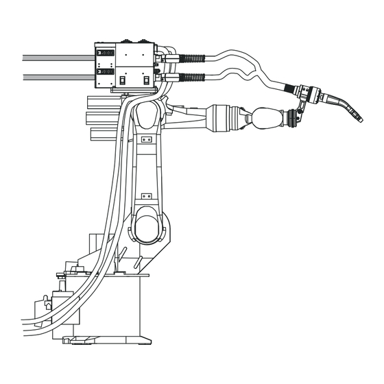
Page 29: System Configurations
System configurations TWIN Push sys- (13) tem overview (14) (16) (15) (10) (11) (17) (12) (19) (18) Welding wire drum Depending on the application, two WFi R REEL unwinding wirefeeders can be used additionally for optimal wirefeeding. Wirefeeding hoses Robot controls... -
Page 30: Twin Push/Pull, Cmt System Overview
+ OPT/i MTB 11.5° sym. (17) TWIN welding torch change station TXi TWIN (18) Connection cable from robot controls to welding torch service station (19) Robacta TSS /i welding torch service station TWIN Push/Pull, CMT system (1) (2) (4) (5) (12a) (13) (14) -
Page 31: More Configuration Options
+ TU podium (screwed in place) HP 95i CON /G /10 m interconnecting hosepack (10) Welding wire drum 2 (11) Welding wire drum 1 Depending on the application, two WFi R REEL unwinding wirefeeders can be used additionally for optimal wirefeeding. (12) OPT/i WF Tower + Mounting WF Twin Tower (12a) - Page 32 WF 30i TWIN + MHP TWIN torch hosepack + TXi torch body coupling + Adapter TWIN-MTB Single + MTB Single welding torch ------------------------------------------------------- = single wire application With a TXi TWIN welding torch change station and the corresponding torch body couplings, an automated changeover from a TWIN welding torch to a single weld- ing torch and vice versa can be performed.
-
Page 33: System Components
System components... -
Page 35: Wf 30I R /Twin
Intended Use The device is intended exclusively for wirefeeding in automated MIG/MAG weld- ing in combination with Fronius system components. Any other use does not con- stitute proper use. The manufacturer accepts no liability for any damage result- ing from improper use. -
Page 36: Warning Notices On The Device
The safety symbols warn against operating the equipment incorrectly, as this may result in serious in- jury and damage to property. Part No.: www.fronius.com Ser.No.: IEC 60 974-5/-10 Cl.A IP 23 60 V 1.2 A... - Page 37 Dispose of old devices in accordance with safety rules and not in normal domest- ic waste. Keep hands, hair, loose clothing, and tools away from moving parts, such as: Do not reach into rotating gears of the wire drive or into rotating drive parts. Covers and side parts must only be opened/removed during maintenance and re- pair work.
-
Page 38: Description Of The Warnings On The Device
Description of Warning notices are attached to the device for certain device versions. the warnings on the device The arrangement of the symbols may vary. Warning! Caution! The symbols represent possible dangers. Drive rollers can injure fingers. The welding wire and drive parts are under welding voltage during opera- tion. - Page 39 Use forced-air ventilation or local extraction to remove welding fumes. Remove welding fumes with a fan. Welding sparks can cause an explosion or fire. Keep flammable materials away from the welding process. Do not perform welding near flammable materials. Welding sparks can cause a fire. Have fire extinguishers ready. If neces- sary, have a supervisor ready who can operate the fire extinguisher.
-
Page 40: Interconnecting Hosepack
Interconnecting hosepack Interconnecting hosepack G = gas-cooled interconnecting hosepack, W = water-cooled interconnecting hosepack The interconnecting hosepacks connect the power sources to the TWIN wirefeeder or the two robot wirefeeders. In TWIN welding systems, one water-cooled and one gas-cooled interconnecting hosepack are used. -
Page 41: Torch Hosepack
The water-cooled TWIN torch hosepack connects the TWIN wirefeeder to the TWIN welding torch the two robot wirefeeders to the TWIN welding torch For TWIN Push/Pull and TWIN CMT applications, the TWIN drive unit is integ- rated into the torch hosepack. Scope of supply... -
Page 42: Crashbox
CrashBox. ▶ The torch hosepack must not whip around or get stuck when moving. ▶ If possible, check all movement situations with Fronius system components in a simulation as early as the concept phase. Note on the re- NOTE! -
Page 43: Also Required For The Installation
93 Nm / 68.60 lb-ft Scope of supply (2)(3) (5)(6) (1) (2) (3) (4) (3) Scope of supply CrashBox /i XXL (TWIN Push) Scope of supply CrashBox /d TWIN (TWIN Push/Pull, CMT) CrashBox /i holder NOTE! 1-ear clamp * Locking ring, 2-part *... -
Page 44: Scope Of Supply Clamp System (Twin Push)
Scope of supply clamp system (TWIN Push) Scope of supply index disk (TWIN Push) Scope of supply The drive unit support is available with drive unit sup- 30° and with 45°. port (TWIN Push/Pull, CMT) -
Page 45: Robot Welding Torch
Robot welding torch Robot welding torches Example: MTB 900i The water-cooled MTB 2x500i R and MTB 900i R robot welding torches transfer the arc power to the workpiece. The TWIN welding torches are designed for use with the CrashBox /i XXL and are available in two versions: with contact tips arranged one over the other, welding torch angle 30°... -
Page 46: Mtb 2X500I R - Contact Tip Tilt Angle
11.5° OPT/i MTB TWIN 11.5° sym. Tilt angle of the contact tips toward each other = 11.5° Details of the assembly components can be found under the adjacent link in the Fronius online spare parts catalog. https://spareparts.fronius.com Search: MTB 2x500 NOTE! The tilt angle-dependent dimensions of the welding torch can be found in the technical data from page 168. -
Page 47: Twin-Mtb Single Adapter
TWIN-MTB Single adapter TWIN-MTB Single adapter (A) hosepack side, (B) torch body side, 1 = welding line 1, 2 = welding line 2 With the aid of the TWIN-MTB Single adapter, the TWIN welding system can be operated with a single torch body. The adapter combines gas and compressed air lines as well as the wirefeeding lines of both welding lines. -
Page 49: Welding Technology Aspects
Welding Technology Aspects... -
Page 51: Welding Technology Aspects
Welding Technology Aspects Shielding gases Material Shielding gas for TWIN weld- Non-alloyed and low-alloy steels ArCO , ArO and ArCO mixtures ing processes CrNi steels, high-alloy steels ArCO mixtures, proportion of active gas max. 2.5% mixtures, proportion of active gas max. -
Page 52: Work Angle Of The Welding Torch
Work angle of Select the work angle of the welding the welding torch so that the lead wire electrode (= torch wire electrode of the lead power source) is in a neutral to slightly lead- ing position. Approx. 90–100° for steel applications Approx. -
Page 53: Application Recommendations For The Tilt Angles Of The Contact Tips
Application re- By material: commendations for the tilt angles Tilt angle of the contact Application 0° 4° 8° 11.5° tips Aluminum Steel ferritic Austenitic steel, CrNi Lead/trail = PMC TWIN/PMC TWIN or PCS TWIN/PMC TWIN Lead/trail = PMC TWIN/CMT TWIN or CMT TWIN/CMT TWIN According to seam geometry (for steel): Tilt angle Application... -
Page 54: Welding Start Sequence For Cmt Twin
Welding start se- quence for CMT TWIN L = Lead wire electrode, T = Trail wire electrode Both wire electrodes move towards the workpiece Both wire electrodes make contact with the workpiece The lead wire electrode starts the welding process, the trail wire electrode moves away from the workpiece and waits for the start signal of the lead wire electrode = welding start delay As soon as the trail wire electrode receives the start signal, it also starts the... -
Page 55: Twin Characteristics
TWIN Characteristics General Only PMC TWIN characteristics with the following properties are available for the TWIN welding process: Universal Characteristic packages for conventional welding tasks The characteristics are optimized for a wide range of applications in synchronized TWIN welding. The pulse synchronization ratio and the lead/trail phase shift are supported, provided that a TWIN universal characteristic is in use at both power sources. -
Page 56: Available Twin Characteristics
Available TWIN PR = Process characteristics Stahl: Wire diameter Shielding gas Property 4256 C1 CO 100% 0.9 mm TWIN universal 4257 M21 Ar + 15–20% CO 0.9 mm TWIN universal 4258 M20 Ar + 5–10% CO 0.9 mm TWIN universal 3940 M21 Ar + 15–20% CO 1.0 mm... - Page 57 Wire diameter Shielding gas Property 3893 M20 Ar + 5–10% CO 1.3 mm TWIN PCS 3846 M21 Ar + 15–20% CO 1.4 mm TWIN PCS 3840 M21 Ar + 15–20% CO 1.6 mm TWIN PCS 3841 M20 Ar + 5–10% CO 1.6 mm TWIN PCS 4021...
- Page 58 CrNi 19 9/19 12 3: Wire diameter Shielding gas Property 4024 M12 Ar + 2–5% CO 1.2 mm TWIN universal 4261 M12 Ar + 2–5% CO 1.2 mm TWIN universal 4026 M12 Ar + 2–5% CO 1.2 mm TWIN PCS CrNi 18 8/18 8 6: Wire diameter Shielding gas...
- Page 59 AlMg4.5 Mn (Zr): Wire diameter Shielding gas Property 4147 1.2 mm I1 Ar 100% TWIN universal 4287 1.2 mm I3 Ar + 30% He TWIN universal 4041 1.6 mm I1 Ar 100% TWIN universal 4053 1.6 mm I3 Ar + 30% He TWIN universal 4289 1.2 mm...
-
Page 60: Slaghammer
Wire diameter Shielding gas Property 4246 1.2 mm I1 100% Ar TWIN PCS 4286 1.2 mm I3 Ar + 30% He TWIN PCS 4294 1.6 mm I1 Ar 100% TWIN PCS AlSi 5: Wire diameter Shielding gas Property 4260 1.2 mm I1 Ar 100% TWIN universal 4265... -
Page 61: Twin Welding Processes
TWIN Welding Processes TWIN welding Lead wire electrode Trail wire electrode processes - over- (= lead power source) (= trail power source) view Welding direction PMC TWIN PMC TWIN PCS TWIN PCS TWIN PMC TWIN CMT TWIN PCS TWIN CMT TWIN CMT TWIN CMT TWIN Single wire (Pulse*/Standard*/PMC*/LSC*/CMT*) -
Page 62: Pmc Twin/Pmc Twin
CMT droplet melting phase CMT start of arcing phase CMT droplet detachment Welding current of the lead power source Welding current of the trail power source Welding direction PMC TWIN/PMC TWIN I (A) t (s) > I Welding current time curves and schematic representation of the material transition P = phase shift Time coordination of the power sources The PMC processes of the two process lines are synchronized with each other. -
Page 63: Pcs Twin / Pcs Twin
A combination of PMC Single characteristics and PMC TWIN characteristics (lead/trail or trail/lead) does not lead to synchronization. NOTE! The TWIN process PMC TWIN/PMC TWIN should generally be used for all welding applications. PCS TWIN / PCS I (A) TWIN t (s) Welding current time curves and schematic representation of the material transition PCS TWIN characteristics are predominantly used in order to weld with a modi-... -
Page 64: Pmc Twin / Cmt Twin
PMC TWIN / CMT TWIN Schematic representation of the material transition Advantages: Deep penetration of the lead wire electrode High deposition rate at the lead wire electrode Very good seam filling due to the trail wire electrode High process stability The TWIN welding process PMC TWIN / CMT TWIN can be used for both welding directions. -
Page 65: Single Wire (With A Twin Welding Torch):Pmc/Pulse/Lsc/Standard/Cmt
The TWIN welding process CMT TWIN / CMT TWIN can be used for both welding directions. Single wire (with Welding current time curves and schematic representation of the material a TWIN welding transition for the lead power source torch): PMC/ I (A) I (A) Pulse/LSC/... - Page 66 Welding current time curves and schematic representation of the material transition for the trail power source I (A) I (A) t (s) t (s) PMC/Pulse LSC/Standard I (A) t (s) Single wire welding In single wire welding, a signal is emitted by the robot controls, meaning that only one power source welds.
-
Page 67: Twin Process Parameters
The start parameters of the trail arc are automatically adapted to the prevailing conditions of the lead arc. The trail arc starts without contact in TWIN Push systems and with a synchron- ized SFI (spatter-free ignition) in TWIN Push/Pull systems. -
Page 68: Pulse Synchronization Ratio
When set manually, an ignition delay of 0–2 seconds can be set. The start of the trail arc is synchronized. The function can be deactivated. In this case, the trail arc is ignited immediately and is not synchronized. Information on the power source display Pulse synchron- Adjustment range: auto, 1/1, 1/2, 1/3 ization ratio... -
Page 69: Lead/Trail Phase Shift
Lead/trail phase Adjustment range: auto, 0–95% shift Factory setting: auto Only active if the same PMC TWIN characteristic is set for both wire electrodes. Lead/trail phase shift enables the time of droplet detachment to be freely selec- ted for the trail arc. As the trail droplet detachment does not have to take place in the quiescent current phase of the lead arc, an arc blow between the two arcs can be counteracted. -
Page 70: Twin Synchropulse
TWIN SynchroPulse SynchroPulse SynchroPulse is available for all process (Standard / Pulse / LSC / PMC). welding The cyclic change of the welding power between two operating points with Syn- chroPulse achieves a finely rippled weld appearance and a non-continuous heat input. -
Page 71: Twin Push Welding Parameter Standard Values
TWIN Push welding parameter standard values Standard values NOTE! for fillet welds, The following data are standard values determined under laboratory conditions. welding position Shielding gas and filler metal used: Shielding gas M20 Ar + 5-15% CO Filler metal ER70S-6 Wire diameter 1.2 mm... - Page 72 26.2 27.6 15.0 19.5 12.0 30.0 24.6 27.6 19.6 17.7 10.1 27.9 20.0 24.9 20.9 15.3 10.0 27.4 22.5 27.0 26.5 16.4 26.9...
-
Page 73: Standard Values For Fillet Welds, Pb Welding Position
Standard values NOTE! for fillet welds, PB welding posi- The following data are standard values determined under laboratory conditions. tion Shielding gas and filler metal used: Shielding gas M20 Ar + 5-15% CO Filler metal ER70S-6 Wire diameter 1.2 mm Characteristic (lead + trail) PMC TWIN Universal 3565 18.0... - Page 74 22.0 27.0 12.1 17.4 12.0 28.2...
-
Page 75: Twin Push/Pull Welding Parameter Standard Values
TWIN Push/Pull welding parameter standard val- Standard values NOTE! for fillet welds, PB welding posi- The following data are standard values determined under laboratory conditions. tion Shielding gas and filler metal used: Shielding gas M21 Ar + 15-20% CO2 Filler metal... -
Page 76: Standard Values For Lap Joints, Welding Position Pb
Standard values NOTE! for lap joints, The following data are standard values determined under laboratory conditions. welding position Shielding gas and filler metal used: Shielding gas M21 Ar + 15-20% CO2 Filler metal ER70S-6 Wire diameter 1.2 mm Contact tip tilt angle 11.5°... -
Page 77: Twin Cmt Welding Parameter Standard Values
TWIN CMT welding parameter standard values Standard values NOTE! for fillet welds, The following data are standard values determined under laboratory conditions. PB welding posi- tion Shielding gas and filler metal used: Shielding gas M21 Ar + 15-20% CO2 Filler metal ER70S-6 Wire diameter 1.2 mm... -
Page 78: Standard Values For Lap Joints, Welding Position Pb
Standard values NOTE! for lap joints, The following data are standard values determined under laboratory conditions. welding position Shielding gas and filler metal used: Shielding gas M21 Ar + 15-20% CO2 Filler metal ER70S-6 Wire diameter 1.2 mm Contact tip tilt angle 8°... -
Page 79: Operating Controls, Connections And Mechanical Components
Operating controls, connections and mechanical components... -
Page 81: Wf 30I R /Twin
WF 30i R /TWIN Safety WARNING! Danger from incorrect operation and work that is not carried out properly. This can result in serious personal injury and damage to property. ▶ All the work and functions described in this document must only be carried out by technically trained and qualified personnel. -
Page 82: Wirefeeder Side
Coolant connection For connecting the coolant connection from the interconnecting hosep- (10) Coolant supply connection (blue) For connecting the coolant hose from the torch hosepack (11) Coolant return connection (red) For connecting the coolant hose from the torch hosepack (12) Compressed air connection IN OPT/i WF gas purging option 16 bar Wirefeeder Side... -
Page 83: Function Of The Gas-Test, Wire-Return, And Wire-Threading Buttons
(11) Gas-test button 2 for setting the required gas volume on the pressure regulator (12) Wire-threading button 2 for threading the wire electrode into the torch hosepack without gas or current (13) 4-roller drive 2 (14) Clamping lever 2 for adjusting the contact pressure of the feed rollers (15) Protective cover of the 4-roller drive 2 (16) - Page 84 Wire-threading button There are two options available for the wire threading: Option 1 Thread the wire electrode at the preset feeder inching speed: Press and hold the wire-threading button After pressing the wire-threading button, the wire electrode will be threaded in by 1 mm (0.039 in.) After a brief pause, the wirefeeder continues threading in the wire electrode –...
-
Page 85: Wirefeeder Rear
Wirefeeder rear (3) (4) Function Wire infeed tube 1 Wire infeed tube 2 Dummy cover Dummy cover Dummy cover Dummy cover... -
Page 86: Mhp 2X450I Rd/W/Fsc Incl. Wf 60I Twin Drive /W
MHP 2x450i RD/W/FSC incl. WF 60i TWIN Drive /W Safety WARNING! Danger from incorrect operation and work that is not carried out properly. This can result in serious personal injury and damage to property. ▶ All the work and functions described in this document must only be carried out by technically trained and qualified personnel. -
Page 87: Mhp 2X450I Rd/W/Fsc Incl. Wf 60I Twin Drive /W - Control Panel
MHP 2x450i Wire-return button* RD/W/FSC incl. Retracts the wire electrode WF 60i TWIN without gas or current Drive /W – con- trol panel Gas-test button* For setting the required gas volume on the gas pressure reg- ulator Wire-threading button* For threading the wire elec- trode into the torch hosepack without gas or current LEDs 1/2/TWIN/External... - Page 88 Teach mode is used for creating the robot program. When the teach mode is active, bending of the wire electrode is avoided when setting up the robot. In TWIN teach mode (with both wire electrodes), the lead wire electrode has a higher scanning frequency than the trail wire electrode. Details on the teach mode can be found in the operating instructions "Sig- nal descriptions interface TPS /i", 42,0426,0227,xx.
-
Page 89: Interconnecting Hosepack
Interconnecting hosepack Interconnecting SpeedNet cable Hosepack—Con- Coolant hoses nections Protective gas shield hose Power cable W = water-cooled interconnecting hosepack G = gas-cooled interconnecting hosepack... -
Page 90: Twin-Mtb Single Adapter
TWIN-MTB Single adapter TWIN-MTB Single adapter – connectors (1) (2) (10) (A) Hosepack side (B) Torch body side Current/coolant Welding line 1 Shielding gas Wire electrode welding line 2 Current/coolant Welding line 2 Wire electrode Welding line 1 Compressed air Common compressed air and inert gas output Common power contacts/coolant return Common power contacts/coolant flow... -
Page 91: Installing The System Components - Twin Push
Installing the system components - TWIN Push... -
Page 93: Safety-Installation And Commissioning
Safety—Installation and Commissioning Safety WARNING! Incorrect operation and incorrectly performed work can cause serious injury and property damage. ▶ All work listed in this document may only be performed by trained specialist personnel. ▶ All functions described in this document may only be used by trained spe- cialist personnel. -
Page 94: Insulated Guiding Of The Wire Electrode To The Wirefeeder
Insulated Guid- WARNING! ing of the Wire Electrode to the Risk of injury and property damage, as well as impairment of the welding result, Wirefeeder due to ground fault or earth leakage of a non-insulated wire electrode. ▶ In automated applications, only guide the wire electrode from the welding wire drum, large spool or wirespool to the wirefeeder with insulation (for ex- ample using a wirefeeding hose). -
Page 95: Before Installation And Initial Operation
Before installation and initial operation Setup regula- WARNING! tions Toppling or falling devices can be deadly. ▶ Set up all system components, upright brackets and trolleys so that they are stable on a flat and solid surface. The wirefeeder has been tested according to protection class IP 23. This means: Protection against the penetration of solid foreign bodies with a diameter of more than 12.5 mm (0.49 in.) Protection against spraywater at any angle up to 60°... - Page 96 Installing the CrashBox, torch hosepack, and TWIN welding torch Mount the robot flange and CrashBox on the robot Insert the inner liners into the torch hosepack Install the clamp on the CrashBox Insert the torch hosepack into the clamp Connect the CrashBox cable Connect the torch hosepack to the wirefeeder Insert the inner liners into the TWIN welding torch Install the torch body coupling...
-
Page 97: Install Twin Wirefeeder And Accessories On The Robot
Install TWIN Wirefeeder and Accessories on the Robot Installing the wirefeeder on the robot M8 x 25 mm 25 Nm 18.44 ft·lb Installation of the wirefeeder holder depends on the robot. Follow the Installation Instructions for the wirefeeder holder! M8 x 30 mm 10 Nm 25 Nm 7.38 ft·lb... -
Page 98: Installing The Side Holders For The Interconnecting Hosepacks On The Robot
Installing the Installation of the side holder depends side holders for on the robot. the intercon- Follow the Installation Instructions! necting hosep- acks on the ro- Example of a side holder on the robot for TWIN Push systems... -
Page 99: Lay, Install And Connect Interconnecting Hosepacks
Lay, Install and Connect Interconnecting Hosep- acks Connecting the NOTE! interconnecting hosepacks to the If the interconnecting hosepack is laid incorrectly it can have a significant influ- wirefeeder ence on the welding results, a stable welding process is not guaranteed! ▶... - Page 100 Connect the in- IMPORTANT! When connecting the interconnecting hosepacks, observe marks 1 terconnecting and 2 on the interconnecting hosepacks and on the power sources: hosepacks to the 1 = water-cooled interconnecting hosepack power source, 2 = gas-cooled interconnecting hosepack cooling unit and TWIN Controller NOTE! If the interconnecting hosepack is laid incorrectly it can have a significant influ-...
-
Page 101: Install Crashbox, Torch Hosepack And Twin Welding Torch
Install CrashBox, Torch Hosepack and TWIN Welding Torch Mounting the Observe the torques when fitting the CrashBox /i on robot flange: the robot Max. tightening torque for screws with strength class 8.8 3.3 Nm / 2.43 lb-ft 5.0 Nm / 3.69 lb-ft 6.0 Nm / 4.43 lb-ft 27.3 Nm / 20.14 lb-ft 54 Nm / 39.83 lb-ft... -
Page 102: Mounting The Crashbox /I Dummy On The Robot
Mounting the Observe the torques when fitting the CrashBox /i robot flange: Dummy on the robot Max. tightening torque for screws with strength class 8.8 3.3 Nm / 2.43 lb-ft 5.0 Nm / 3.69 lb-ft 6.0 Nm / 4.43 lb-ft 27.3 Nm / 20.14 lb-ft 54 Nm / 39.83 lb-ft 93 Nm / 68.60 lb-ft... -
Page 103: Installing The Inner Liner In The Torch Hosepack
6 Nm / 4.43 lb-ft 3,3 Nm / 2.43 lb-ft Installing the in- NOTE! ner liner in the So that the inner liner can be correctly installed, lay the hosepack out straight torch hosepack when installing the inner liner. After insertion, ensure that the inner liner is right at the front in the hosepack. -
Page 104: Installing The Torch Hosepack
IMPORTANT! The screws for securing the inner liners must not be loosened! Screw the clamping nipple onto the inner liner up to the stop. The inner liner needs to be visible through the hole in the fastener. Installing the torch hosepack 42 Nm... - Page 105 NOTE! To avoid jamming the welding torch hosepack: ▶ Tighten the screws crosswise ▶ Observe the specified sequence when tightening ▶ Pre-tighten screws with 1 Nm, then tighten with 4 Nm 1 Nm 4 Nm Tighten screws crosswise, 1 Nm Tighten screws crosswise, 4 Nm...
- Page 106 IMPORTANT! When connecting the torch hosepack, pay attention to marks 1 and 2 on the torch hosepack and on the wirefeeder. Connect coolant hoses from the weld- ing torch according to the color mark- ings on the coolant supply and coolant return connections...
-
Page 107: Mounting The Torch Body On The Twin Torch Hosepack
Mounting the NOTE! torch body on the TWIN torch The coupling areas between the torch body and TWIN torch hosepack must al- hosepack ways be free of oil, grease, and dust, and be dry. Visually check that the springs are present, not deformed or otherwise damaged. -
Page 108: Checking The Function Of The Torch Body Coupling
BY2,0201,4863 42,0411,1315 Checking the NOTE! function of the torch body coup- Flawless operation of the interchangeable coupling can only be guaranteed with ling a vertical alignment facing down. Actuate the torch body coupling five times using a robot signal and check whether the torch body coupling opens and closes If the torch body coupling opens and closes correctly, check the manual locking of a torch body in the torch body coupling. - Page 109 Torch body coupling closed Torch body coupling open NOTE! The locking balls of the torch body coupling are intended for dry operation. ▶ Do not lubricate the locking balls. NOTE! Always insert the torch body into the torch body coupling so that it is straight and until it reaches the stop.
- Page 110 If the torch body can be correctly locked in the torch body coupling by hand, then the torch body coupling is ready for use.
-
Page 111: Installing The System Components - Twin Push/Pull, Cmt
Installing the system components - TWIN Push/Pull, CMT... -
Page 113: Safety-Installation And Commissioning
Safety—Installation and Commissioning Safety WARNING! Incorrect operation and incorrectly performed work can cause serious injury and property damage. ▶ All work listed in this document may only be performed by trained specialist personnel. ▶ All functions described in this document may only be used by trained spe- cialist personnel. -
Page 114: Insulated Guiding Of The Wire Electrode To The Wirefeeder
Insulated Guid- WARNING! ing of the Wire Electrode to the Risk of injury and property damage, as well as impairment of the welding result, Wirefeeder due to ground fault or earth leakage of a non-insulated wire electrode. ▶ In automated applications, only guide the wire electrode from the welding wire drum, large spool or wirespool to the wirefeeder with insulation (for ex- ample using a wirefeeding hose). -
Page 115: Before Installation And Initial Operation
Before installation and initial operation Setup regula- WARNING! tions Toppling or falling devices can be deadly. ▶ Set up all system components, upright brackets, and trolleys so that they are stable on a flat and solid surface. The system components have been tested according to at least protection class IP 20. -
Page 116: Installation - Overview Of Twin Push/Pull, Cmt
The following overview covers the installation work required for a Push/Pull overview of TWIN welding system in accordance with the system overview on page 30. TWIN Push/Pull, The installation of similar TWIN systems is carried out analogously to this. Initial situation: The robot and robot controls are correctly positioned and fastened in the welding cell. - Page 117 Mount the Y-piece from the torch hosepack on the support Y-piece suspend the Y-piece from the balancer Fix the torch hosepack to the side holder or to the wire buffers Connect the torch hosepack to the TWIN wirefeeder Insert the inner liners into the TWIN welding torch Insert/route the inner liners and inlet/outlet nozzles into the TWIN torch hosepack Install the torch body coupling...
- Page 118 Set the TWIN characteristics on both power sources (welding process/filler metal/change material settings... step 4 – select the characteristic from the characteristics available for each welding process) Set stick out If necessary, carry out system calibration (e.g., if there is a WF REEL unwind- ing wirefeeder in the system) Define the lead/trail signal on the robot controls Set TWIN welding parameters...
-
Page 119: Mounting The Balancer Mounting On The Y-Piece
Mounting the balancer mounting on the Y-piece Mounting the The balancer mounting Y-piece is used when the Y-piece is not mounted on the balancer mount- robot. ing on the Y- piece 10 Nm 7.38 ft·lb... -
Page 120: Mounting The Support Y-Piece On The Robot
Mounting the support Y-piece on the robot Mounting the Installation of the support Y-piece de- support Y-piece pends on the robot. on the robot Follow the Installation Instructions! Example: Y-piece on a robot... -
Page 121: Installing The Side Holder On The Robot
Installing the side holder on the robot Installing the Installation of the side holder depends side holder on on the robot. the robot Follow the Installation Instructions! Example: Side holder on a robot... -
Page 122: Installing Wire Buffers On The Robot
Installing wire buffers on the robot TWIN-CMT - in- Installation of the side holder depends stalling wire buf- on the robot. fers on the robot Follow the Installation Instructions! Example of a side holder on a robot M5 x 16 mm 6 Nm 4.43 ft·lb NOTE! - Page 123 M6 x 12 mm 10 Nm 7.38 ft·lb Steps 3 + 4: Attach stickers to the wire buffers and define welding lines 1 and 2 on the wire buffers; Example according to the figure: right wire buffer = welding line 1, left wire buffer = welding line 2 NOTE! For detailed information on the wire buffer, refer to the Operating Instructions for the wire buffer (42,0410,1254).
-
Page 124: Install Crashbox, Torch Hosepack And Twin Welding Torch
Install CrashBox, Torch Hosepack and TWIN Welding Torch Mounting the Observe the torques when fitting the CrashBox /d robot flange: TWIN on the ro- Max. tightening torque for screws with strength class 8.8 3.3 Nm / 2.43 lb-ft 5.0 Nm / 3.69 lb-ft 6.0 Nm / 4.43 lb-ft 27.3 Nm / 20.14 lb-ft 54 Nm / 39.83 lb-ft... -
Page 125: Mounting The Crashbox Twin Drive /I Dummy On The Robot
Mounting the Observe the torques when fitting the CrashBox TWIN robot flange: Drive /i Dummy on the robot Max. tightening torque for screws with strength class 8.8 3.3 Nm / 2.43 lb-ft 5.0 Nm / 3.69 lb-ft 6.0 Nm / 4.43 lb-ft 27.3 Nm / 20.14 lb-ft 54 Nm / 39.83 lb-ft 93 Nm / 68.60 lb-ft... -
Page 126: Installing The Torch Hosepack With Twin Drive Unit
3,3 Nm 2.43 lb·ft * Dowel pin Installing the The TWIN drive unit is already mounted on the torch hosepack on delivery. torch hosepack To make things simpler, the TWIN drive unit is shown without the torch hosepack with TWIN drive in the following illustrations. - Page 127 M5 x 12 mm ft·lb Do not tighten the screw connection yet! M8 x 25 mm 18 Nm 13.28 ft·lb * = Dowel pin (2x) M5 x 12 mm 10 Nm 7.38 ft·lb 6 Nm 4.43 ft·lb Connect the CrashBox cable to the drive unit and to the CrashBox...
- Page 128 Mounting the Y-piece from the torch hosepack on the robot support Y-piece M8 x 16 mm 25 Nm 18.44 ft·lb NOTE! The mounting position A, B, or C depends on the torch hosepack length and the robot. ▶ Follow the Installation Instructions!
-
Page 129: Connecting The Torch Hosepack To The Wirefeeder
Route and fix the torch hosepack to the wire buffers fix the torch hosepack to the side holder NOTE! If torch hosepacks are installed on the robot, make sure that there is no tension or strain in the hosepacks during any movement in a robot axis. ▶... - Page 130 An anti-kink protection ring consists of two half shells, which are screwed to- gether on the corrugated protective hose with two M4 x 10 mm Allen screws. Tightening torque = 1 Nm / 0.74 lb·ft The anti-kink protection rings are available individually as an option from Fronius.
-
Page 131: Mounting The Torch Body On The Twin Drive Unit
Mounting the NOTE! torch body on the TWIN drive The coupling areas between the torch body and TWIN drive unit must always be unit free of oil, grease, and dust, and be dry. Visually check that the springs are present, not deformed or otherwise damaged. -
Page 132: Fitting The Wirefeeding Hoses And Inner Liners
Fitting the wirefeeding hoses and inner liners Inserting the in- For TWIN Push/Pull systems without wire buffers ner liner into the torch hosepack Disconnect the wirefeeding hose from the robot wirefeeder (press white but- ton) Fit the collet Insert the inner liner until it is visible at the sight hole of the drive unit... -
Page 133: Preparing The Twin Drive Unit For Operation
Preparing the TWIN drive unit for operation General The feed rollers are not inserted in the system when first delivered. In order to achieve optimum wire electrode feed, the feed rollers must be suit- able for the diameter and alloy of the wire being welded. NOTE! Danger due to deficient feed rollers. - Page 134 Open the clamping lever Swing out the roller holder Remove the spindle Insert the toothed pressure roller Insert the spindle 1 0 1 Counter with the special key Unscrew the drive roller Remove the drive roller Insert the new drive roller Screw on the new drive roller Install by performing the steps in the reverse order...
-
Page 135: Connecting Wirefeeding Hoses
IMPORTANT! Check the contact pressure before recommissioning! Connecting Connect the wirefeeding hoses in the same way as on the TWIN Push system (see wirefeeding page 146). hoses The following wirefeeding hoses are required: Wire drum - robot wirefeeder Robot wirefeeder - wire buffer... -
Page 137: Installing And Preparing Other System Components, Commissioning
Installing and preparing other sys- tem components, commissioning... -
Page 139: Installing The Robot Welding Torch
Installing the robot welding torch Inserting steel inner liner into the torch body NOTE! The coupling area of the torch body must always be free of oil, grease, and dust, and be dry. -
Page 140: Inserting Plastic Inner Liner Into The Torch Body
Inserting plastic NOTE! inner liner into the torch body The coupling area of the torch body must always be free of oil, grease, and dust, and be dry. When mounting a plastic inner liner, the contact tips must be mounted on the torch body. - Page 141 3 mm Push the inner liner in as far as it will go 2 Nm 3 mm Repeat steps 2–6 for the second wire electrode NOTE! All other available inner liners can be mounted like a plastic inner liner from the coupling side.
-
Page 142: Installing Wear Parts In The Twin Welding Torch
TWIN welding NOTE! torch For detailed information, refer to the Installation Instructions 42,0410,2487 ... OPT/i TWIN 0/4/8/11.5° https://manuals.fronius.com/html/4204102487 Sleeve wear parts NOTE! For detailed information, refer to the Installation Instructions 42,0410,2932 ... OPT/i TWIN 0/4/8/11.5° Sleeve https://manuals.fronius.com/html/4204102932... -
Page 143: Inserting The Inner Liner In The Twin-Mtb Single Adapter
TWIN-MTB The weld line is defined by inserting the inner liner into the respective wire inlet Single adapter on the TWIN-MTB Single adapter. Fronius recommends running single applications on welding line 1. 18 ± 2 Nm 45,0200,1261 42,0411,1315 3 mm... - Page 144 2 Nm 3 mm...
-
Page 145: Preparing Twin Wirefeeder For Operation
Preparing TWIN Wirefeeder for Operation Inserting/chan- CAUTION! ging feed rollers Danger due to feed roller holders shooting upwards. This could result in injury. ▶ When unlocking the clamping lever, keep fingers away from the area to the left and right of the clamping lever. CAUTION! Danger due to open feed rollers. -
Page 146: Connecting Wirefeeding Hoses
Connecting wirefeeding hoses Connect wirefeeding hoses to the welding wire drums Wire straighten- NOTE! When using the OPT/i WF wire straightener option, observe the information in the Operating Instructions 42,0410,1944! -
Page 147: Lay, Install And Connect Interconnecting Hosepacks
Lay, Install and Connect Interconnecting Hosep- acks Connecting in- NOTE! terconnecting hosepacks to the If the interconnecting hosepack is laid incorrectly it can have a significant influ- robot wirefeed- ence on the welding results, a stable welding process is not guaranteed! ▶... - Page 148 Connect the in- IMPORTANT! When connecting the interconnecting hosepacks, observe marks 1 terconnecting and 2 on the interconnecting hosepacks and on the power sources: hosepacks to the 1 = water-cooled interconnecting hosepack power source, 2 = gas-cooled interconnecting hosepack cooling unit and TWIN Controller NOTE! If the interconnecting hosepack is laid incorrectly it can have a significant influ-...
-
Page 149: Connect Twin Controller
Connect TWIN Controller Connect the Connecting power source to the TWIN TWIN Controller Controller via SpeedNet cable with the Power Sources and Connect Inter- TPSi 1 = power source 1 connecting Hosepack TPSi 2 = power source 2 HP CON 1 = interconnecting hosepack HP CON 2 = interconnecting hosepack Connecting the R-C = robot controls... -
Page 150: Connecting The Protective Gas Shield And Grounding Cable
Connecting the Protective Gas Shield and Grounding Cable Connecting Pro- Connect the protective gas shield hoses from the interconnecting hosepacks tective Gas to the protective gas shield supply Shield Connecting the CAUTION! return lead cable Danger due to incorrect routing of the return lead cables! This can result in severely impaired welding results! ▶... -
Page 151: Commissioning
Commissioning Threading the CAUTION! wire electrode Danger of injury and property damage due to welding current and unintentional ignition of an arc. ▶ Before starting work, disconnect the ground earth connection between the welding system and workpiece. CAUTION! Danger of damage to the welding torch due to sharp-edged end of the wire elec- trodes. -
Page 152: Setting The Contact Pressure
The wire electrode can be threaded on the TWIN robot wirefeeder or on the wire electrode TWIN drive unit. Thread the wire electrode in the same way as on the TWIN Push system (see page 151). The following wirefeeding hoses are required:... -
Page 153: Setting The Contact Pressure On The Twin Drive Unit
All components must be installed and connected in accordance with the "In- stallation" chapter. The TWIN welding system may only be fitted and operated with original Fronius components. Do not fit or install any third-party components! ▶ All necessary welding media must be connected to the wirefeeder or to the TWIN drive unit. -
Page 155: Troubleshooting, Maintenance, And Disposal
Troubleshooting, Maintenance, and Disposal... -
Page 157: Troubleshooting
Troubleshooting Safety WARNING! Danger from incorrect operation and work that is not carried out properly. This can result in serious personal injury and damage to property. ▶ All the work and functions described in this document must only be carried out by technically trained and qualified personnel. - Page 158 Power source not working Power source switched on; displays and indicators do not illuminate Cause: Mains lead damaged or broken, mains plug not inserted Remedy: Check mains lead, if necessary insert mains plug Cause: Mains socket or mains plug faulty Remedy: Replace faulty parts Cause:...
- Page 159 Irregular wire speed Cause: Contact tip hole too narrow Remedy: Use suitable contact tip Cause: Inner liner in the welding torch faulty Remedy: Check inner liner for kinks, soiling, etc. Cause: Feed rollers not suitable for wire electrode used Remedy: Use suitable feed rollers Cause: Incorrect contact pressure of the feed rollers...
-
Page 160: Displayed Error Codes
Displayed Error The following error codes may be output on the power source in relation to a Codes TWIN welding process: Welding process does not start after the welding start signal has been activated Cause: No welding torch connected, welding torch has not been detected Remedy: Check the connection between the welding torch and the torch hosepack;... - Page 161 18231 Welding process does not start Cause: The power source is connected to the wrong port on the TWIN Con- troller Remedy: Check that power source 1 is connected to port 1 and power source 2 is connected to port 2 on the TWIN Controller 18232 It is not possible to thread the wire or weld (in TWIN mode) Cause:...
-
Page 162: Service, Maintenance And Disposal
Service, maintenance and disposal General The device only requires minimal of service and maintenance under normal oper- ating conditions. However, several points must be observed for the welding sys- tem to remain operational for years to come. Safety WARNING! Danger from incorrect operation and work that is not carried out properly. This can result in serious personal injury and damage to property. -
Page 163: Weekly
Weekly Clean the welding torch interface, and especially the contacts of the torch identification, with a soft cloth NOTE! If there is more visible contamination or coolant on the welding torch inter- face, clean the interface earlier! Contacts of the torch identification on the weld- ing torch interface Monthly Check 74 mm inner liner piece in the TWIN drive unit, replace if necessary. - Page 164 friendly recycling. Used devices must be returned to a distributor or an approved collection and recycling facility in your area. Proper disposal of used devices pro- motes the sustainable recycling of material resources. Ignoring this may have po- tentially adverse effects on the environment and your health. Packaging materials Materials collected separately.
-
Page 165: Technical Data
Technical data... -
Page 167: Twin Wirefeeder
60% ED 600 A 10% ED 500 A Maximum pressure of shielding gas 7 bar/101.53 psi Coolant Original Fronius Maximum pressure of coolant 5 bar/72.53 psi Wire speed 1 - 30 m/min / 39.37 - 1181.10 ipm Wire drive 4-roller drive Recommended wire diameter 1.2 - 1.6 mm/0.05 - 0.06 in. -
Page 168: Robot Welding Torch
Robot welding torch MTB 900i R Welding current at 10 min/40°C M21 (EN ISO 14175) 100% ED* / 900 A (2 x 450 A) C1 (EN ISO 14175) 100% ED* / 900 A (2 x 450 A) Wire diameter 1.2 - 1.6 mm/0.05 - 0.06 inch * ED = Duty cycle MTB 2x500i R Welding current at 10 min / 40°C... - Page 169 α = 11.5° β = 30° / PB & PA β = 45° / PB & PA s [mm] x [mm] L [mm] H [mm] L [mm] H [mm] [mm] [mm] 60.56 10.44 7.43 327.14 82.00 336.92 136.75 61.55 10.44 7.23 328.00 82.50...
-
Page 170: Water-Cooled Robot Welding Torches
Water-cooled ro- MTB 250i W/R bot welding torches Welding current at 10 min/40°C M21 (EN ISO 14175) 100% ED* / 250 A C1 (EN ISO 14175) 100% ED* / 250 A Wire diameter 0.8 - 1.2 mm/0.032 - 0.047 inch MTB 330i W/R (TX, TXM) Welding current at 10 min/40°C M21 (EN ISO 14175) -
Page 171: Torch Hosepack
43.50 psi Max. coolant pressure 5 bar 72.5 psi ED = Duty cycle MHP 2x450i TWIN Push/Pull hosepack RD/W/FSC incl. WF 60i TWIN Welding current at 10 min/40°C Drive /W M21 (EN ISO 14175) 100% ED* / 2 x 450 A... - Page 172 Lowest cooling capacity as per IEC 1100 W / 1300 W / 1500 W / 1700 W standard 60974-2, depending on the hosepack length Minimum coolant flow Q 1 l/min 0.26 gal (US) / min Minimum coolant pressure p 3 bar 43.50 psi Maximum coolant pressure p 5 bar...
-
Page 173: Interconnecting Hosepacks
Interconnecting hosepacks HP 70i Welding current at 10 min/40°C 40% ED* / 400 A (104°F) 60% ED* / 365 A 100% ED* / 320 A ED = Duty cycle HP 70i, HP PC Welding current at 10 min/40°C 60% ED* / 600 A Cable HD 70 (104°F) 100% ED* / 500 A... - Page 174 CrashBox /i XXL CrashBox /i XXL - technical data & triggering torques and weight-distance diagram Item number 44,0350,3380 Degree of repeatability (1) ± 0.05 mm Triggering torques in x/y direction See table on the next page Maximum displacement in x/y direc- ~ 45°...
- Page 175 Triggering torques and weight-distance diagram The values listed only apply when in a static state!
- Page 176 CrashBox /d TWIN CrashBox /d TWIN - technical data & triggering torques and weight-distance diagram Item number 44,0350,270 Degree of repeatability (1) ± 0.05 mm Triggering torques in x/y direction See table on the next page Maximum displacement in x/y direc- min.
- Page 177 Triggering torques and weight-distance diagram weight [kg] The values listed only apply when in a static state!
Need help?
Do you have a question about the TWIN Push and is the answer not in the manual?
Questions and answers