Table of Contents
Advertisement
Quick Links
Advertisement
Table of Contents
Troubleshooting

Related Manuals for Fronius TWIN Push


Summary of Contents for Fronius TWIN Push
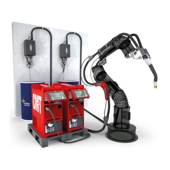
- Page 1 / Perfect Charging / Perfect Welding / Solar Energy Operating instructions TPS/i Robotics welding system TWIN Push TWIN Push/Pull TWIN CMT 42,0426,0277,EA 010-23112021 Fronius prints on elemental chlorine free paper (ECF) sourced from certified sustainable forests (FSC).
-
Page 3: Table Of Contents
Data backup Copyright General information General Application areas Requirements System requirements and minimum equipment TWIN Push System requirements and minimum equipment TWIN Push/Pull System requirements and minimum equipment TWIN CMT Mechanical requirements Electrical Requirements Software requirements Dimensioning of the robot... - Page 4 MHP 2x450i RD/W/FSC incl. WF 60i TWIN Drive /W - mechanical components MHP 2x450i RD/W/FSC incl. WF 60i TWIN Drive /W - control panel Interconnecting hosepack Interconnecting Hosepack—Connections Installation and commissioning – TWIN Push Safety—Installation and Commissioning Safety Insulated Guiding of the Wire Electrode to the Wirefeeder...
- Page 5 Setting the contact pressure Wire straightener Commissioning Requirements Commissioning - start of welding Installation and commissioning - TWIN Push/Pull, CMT Safety—Installation and Commissioning Safety Insulated Guiding of the Wire Electrode to the Wirefeeder Before installation and initial operation Setup regulations...
- Page 6 Mounting the torch body on the TWIN drive unit Mounting the torch body coupling on the TWIN drive unit Checking the function of the torch body coupling Fitting the wirefeeding hoses and inner liners Inserting the inner liner into the torch hosepack Connecting the Protective Gas Shield and Grounding Cable Connecting Protective Gas Shield Connect the grounding cable...
-
Page 7: Safety Instructions
Safety Instructions Explanation of DANGER! Safety Instruc- tions Indicates an immediate danger. ▶ Death or serious injury may result if appropriate precautions are not taken. WARNING! Indicates a possibly dangerous situation. ▶ Death or serious injury may result if appropriate precautions are not taken. CAUTION! Indicates a situation where damage or injury could occur. -
Page 8: Environmental Conditions
The device is intended exclusively for the welding process specified on the rating plate. Utilization for any other purpose, or in any other manner, shall be deemed to be "not in accordance with the intended purpose." The manufacturer is not responsible for any damage resulting from improper use. -
Page 9: Personal Protection And Protection Of Others
This may affect a number of device types in terms of: connection restrictions criteria regarding maximum permissible grid impedance criteria regarding the minimum required short-circuit power both at the interface with the public grid See technical data In this case, the operator or the person using the device should check whether or not the device is allowed to be connected, where appropriate through discussion with the power supply company. -
Page 10: Danger From Flying Sparks
Take the following precautionary measures for fumes and harmful gases: Do not breathe them in. Extract them from the work area using appropriate equipment. Ensure that there is a sufficient supply of fresh air. Ensure that there is a ventilation flow rate of at least 20 m³... -
Page 11: Stray Welding Currents
Ensure suitable personal protection with dry temporary backing or cover with sufficient insulation against the ground potential. The temporary backing or cover must completely cover the entire area between the body and the ground potential. All cables and leads must be secured, undamaged, insulated, and adequately dimen- sioned. -
Page 12: Emc Device Classifications
Position the device with sufficient insulation against electrically conductive environments, e.g., insulation against electrically conductive floors or electrically conductive mounts. Observe the following when using power distribution boards, twin-head mounts, etc.: Even the electrode of the welding torch/electrode holder not in use carries electric poten- tial. -
Page 13: Emf Measures
EMF measures Electromagnetic fields may cause health problems that are not yet known: Effects on the health of persons close by, e.g., those with pacemakers and hearing aids Persons with pacemakers must seek advice from their doctor before staying in the immediate vicinity of the device and the welding process Keep distances between welding power-leads and the head/torso of the welder as great as possible for safety reasons... -
Page 14: Requirement For The Shielding Gas
In the event of crane attachment of the wirefeeder during welding, always use a suitable, insulating wirefeeder hoisting attachment (MIG/MAG and TIG devices). If the device is equipped with a carrier belt or handle, then this is used exclusively for transport by hand. -
Page 15: Danger Posed By Shielding Gas Leak
Danger Posed by Risk of asphyxiation due to uncontrolled shielding gas leak Shielding Gas Shielding gas is colorless and odorless and may suppress the oxygen in the ambient air Leak in the event of leakage. Ensure there is a sufficient supply of fresh air with a ventilation flow rate of at least 20 m³... -
Page 16: Maintenance And Repair
Always secure the shielding gas cylinder well and remove before transporting by crane. Only the original coolant from the manufacturer is suitable for use in our devices due to its properties (electrical conductivity, anti-freeze, material compatibility, flammability, etc.) Only use appropriate original coolant from the manufacturer. Do not mix original coolant from the manufacturer with other coolants. -
Page 17: Safety Symbols
Copyright Copyright of these Operating Instructions remains with the manufacturer. Text and illustrations were accurate at the time of printing. Fronius reserves the right to make changes. The contents of the Operating Instructions shall not provide the basis for any claims whatsoever on the part of the purchaser. If you have any suggestions for im- provement, or can point out any mistakes that you have found in the Operating Instruc- tions, we will be most grateful for your comments. -
Page 19: General Information
General information... -
Page 21: General
General Application areas TWIN welding systems are used exclusively with automated MIG/MAG applications, e.g.: in rail vehicle manufacturing for longitudinal seams and profiles in shipbuilding for fillet welds and profiles in vehicle manufacturing for lap joints and wheel rim welding in automotive engineering in container construction for butt welds, longitudinal seams, lap joints and circumfer- ential welds... -
Page 22: Requirements
Interconnecting hosepacks 1 x HP 95i CON /W /xx m 1 x HP 95i CON /G /xx m 2 x wirefeeding hose (max. 3 m) or Fronius PowerLiner (max. 10 m) 2 x power source TPS 500i / 600i + Welding Package Pulse + firmware official_TPSi_2.2.3-20789.15069.ffw and above... -
Page 23: System Requirements And Minimum Equipment Twin Cmt
Interconnecting hosepacks 1 x HP 95i CON /W /xx m 1 x HP 95i CON /G /xx m 2 x wirefeeding hose (max. 3 m) or Fronius PowerLiner (max. 10 m) 2 x power source TPS 500i / 600i + Welding Package Pulse + firmware official_TPSi_3.2.0-xxxxx.xxxxx.ffw and above... -
Page 24: Mechanical Requirements
The max. inductance in the welding circuit must not exceed 35 µH. Software require- Software version min. 2.2.3 (TWIN Push) or min. 3.2.0 (TWIN Push/Pull, CMT) ments Both power sources must have the same software status. The IP addresses must be set correctly on the power sources. -
Page 25: Ground Connection
Ground connec- Use a separate grounding cable for each power source: tion Separate grounding cables Shared grounding cable, grounding bridge Grounding cable with bifilar winding Grounding cable coiled Further information on connecting the grounding cable can be found from page 97. Note about the NOTE! wirefeed... -
Page 26: Functional Principle
Functional principle Operating Prin- ciple Two wire electrodes (4) and (5) are welded in a weld pool in a shielding gas environ- ment. The welding process is carried out via two independent power sources (1) and (2). The power sources are synchronized by the TWIN Controller. The wirefeed is carried out via a wirefeeder (3) with two drive units. -
Page 27: System Configurations
System configurations TWIN Push sys- (13) (14) tem overview (16) (15) (10) (11) (17) (12) (19) (18) Welding wire drum Depending on the application, two WFi R REEL unwinding wirefeeders can be used additionally for optimal wirefeeding. Wirefeeding hoses Robot controls... -
Page 28: Twin Push/Pull, Cmt System Overview
Connection cable from robot controls to welding torch service station (19) Robacta TSS /i welding torch service station Instead of the TWIN wirefeeder, two single WFi R robot wirefeeders with built-in OPT/i WF PushPull option can also be used. TWIN Push/Pull, CMT system (15) (11) (14) - Page 29 + cooling unit CU 2000i / Part 2 + remote control RC Panel Pro + TU Podium (screwed in place) HP 95i CON /G /10 m interconnecting hosepack (10) OPT/i WF Tower + 2 x OPT/i Mounting WF R Tower (11a) (11) Robot wirefeeder 1 WF 30i R /W * + OPT/i WF R Push Pull...
- Page 30 The balancer mounting Y-piece can also be used instead of the robot support Y- piece.
-
Page 31: System Components
System components... -
Page 33: Wf 30I R /Twin
Intended Use The device is intended exclusively for wirefeeding in automated MIG/MAG welding in combination with Fronius system components. Any other use does not constitute proper use. The manufacturer accepts no liability for any damage resulting from improper use. Proper use also means:... -
Page 34: Warning Notices On The Device
The safety symbols warn against operating the equipment incorrectly, as this may result in serious injury and damage to property. Part No.: www.fronius.com Ser.No.: IEC 60 974-5/-10 Cl.A IP 23 60 V 1.2 A... - Page 35 Dispose of old devices in accordance with safety rules and not in normal domestic waste. Keep hands, hair, loose clothing, and tools away from moving parts, such as: Do not reach into rotating gears of the wire drive or into rotating drive parts. Covers and side parts must only be opened/removed during maintenance and repair work.
-
Page 36: Description Of The Warnings On The Device
Description of the Warning notices are attached to the device for certain device versions. warnings on the device The arrangement of the symbols may vary. Warning! Caution! The symbols represent possible dangers. Drive rollers can injure fingers. The welding wire and drive parts are under welding voltage during operation. Keep hands and metal objects away! An electric shock can be fatal. - Page 37 Welding sparks can cause an explosion or fire. Keep flammable materials away from the welding process. Do not perform weld- ing near flammable materials. Welding sparks can cause a fire. Have fire extinguishers ready. If necessary, have a supervisor ready who can operate the fire extinguisher. Do not weld on drums or closed containers.
-
Page 38: Interconnecting Hosepack
Interconnecting hosepack Interconnecting hosepack G = gas-cooled interconnecting hosepack, W = water-cooled interconnecting hosepack The interconnecting hosepacks connect the power sources to the TWIN wirefeeder or the two robot wirefeeders. In TWIN welding systems, one water-cooled and one gas-cooled interconnecting hosep- ack are used. -
Page 39: Torch Hosepack
The water-cooled TWIN torch hosepack connects the TWIN wirefeeder to the TWIN welding torch the two robot wirefeeders to the TWIN welding torch For TWIN Push/Pull and TWIN CMT applications, the TWIN drive unit is integrated into the torch hosepack. Scope of supply... -
Page 40: Crashbox
CrashBox General The CrashBox /i is a protection device for the torch body and the torch body coup- ling. In the event of a collision, the CrashBox emits a signal to the robot controls, which causes the robot controls to stop the robot immediately. -
Page 41: Scope Of Supply
Scope of supply CrashBox /i holder 1-ear clamp * Locking ring, 2-part * Bellows Cylinder head screws M4 x 16 mm Magnetic ring Mounted on bellows (4) on delivery (2)(3) (5)(6) CrashBox /i XXL scope of supply NOTE! Do not assemble the CrashBox /i holder (1) and magnetic ring (6) before installing on the robot. -
Page 42: Robot Welding Torch
Robot welding torch Safety CAUTION! Burning hazard due to hot torch body, hot torch body coupling, as well as other hot welding torch components. Before starting work on the torch body, the torch body coupling, and all other welding torch components: ▶... -
Page 43: Tilt Angle Of The Contact Tips
Tilt angle of the Depending on the application, different tilt contact tips angles of the contact tips toward each oth- er of 4°, 8° and 11.5° are available for the TWIN welding torches. Corresponding assembly components are required for each angle: 4°... -
Page 45: Welding Technology Aspects
Welding Technology Aspects... -
Page 47: Welding Technology Aspects
Welding Technology Aspects Shielding gases Material Shielding gas for TWIN welding Non-alloyed and low-alloy steels ArCO , ArO , and ArCO mixtures processes CrNi steels, high-alloy steels ArCO mixtures, proportion of active gas max. 2.5% mixtures, proportion of active gas max. ArCO He mixtures, proportion of active gas max. -
Page 48: Work Angle Of The Welding Torch
Work angle of the Select the work angle of the welding torch welding torch so that the lead wire electrode (= wire electrode of the lead power source) is in a neutral to slightly leading position. Approx. 90–100° for steel applications Approx. -
Page 49: Welding Start Sequence For Cmt Twin
Welding start se- quence for CMT TWIN L = Lead wire electrode, T = Trail wire electrode Both wire electrodes move towards the workpiece Both wire electrodes make contact with the workpiece The lead wire electrode starts the welding process, the trail wire electrode moves away from the workpiece and waits for the start signal of the lead wire electrode = welding start delay As soon as the trail wire electrode receives the start signal, it also starts the welding... -
Page 50: Twin Characteristics
TWIN Characteristics General Only PMC TWIN characteristics with the following properties are available for the TWIN welding process: Universal Multi arc Cladding The same TWIN characteristic must be selected on both process lines. Prerequisites for using a PMC TWIN characteristic: Welding Package Pulse on both power sources Both power sources must be connected to the TWIN Controller Available TWIN... - Page 51 Material Wire diamet- Shielding gas Property 4018 Steel 1.0 mm M21 Ar + 15-20% CO TWIN PCS 4019 Steel 1.0 mm M20 Ar + 5-10% CO TWIN universal 4020 Steel 1.0 mm M20 Ar + 5-10% CO TWIN PCS 4021 Steel 1.0 mm M21 Ar + 15-20% CO...
-
Page 52: Twin Welding Processes
TWIN Welding Processes TWIN welding Lead wire electrode Trail wire electrode processes - over- (= lead power source) (= trail power source) view Welding direction PMC TWIN PMC TWIN PCS TWIN PCS TWIN PMC TWIN CMT TWIN PCS TWIN CMT TWIN CMT TWIN CMT TWIN Single wire (Pulse*/Standard*/PMC*/LSC*/CMT*) -
Page 53: Pmc Twin / Pmc Twin
CMT droplet melting phase CMT start of arcing phase CMT droplet detachment Welding current of the lead power source Welding current of the trail power source Welding direction PMC TWIN / PMC TWIN I (A) t (s) > I Welding current time curves and schematic representation of the material transition P = phase shift Time coordination of the power sources The PMC processes of the two process lines are synchronized with each other. -
Page 54: Pcs Twin / Pcs Twin
NOTE! The TWIN process PMC TWIN / PMC TWIN should generally be used for all welding applications. PCS TWIN / PCS I (A) TWIN t (s) Welding current time curves and schematic representation of the material transition PCS TWIN characteristics are predominantly used in order to weld with a modified spray arc at the lead wire electrode and a pulsed arc at the trail wire electrode. -
Page 55: Pmc Twin/Cmt Twin
PMC TWIN/CMT TWIN Schematic representation of the material transition Advantages: Deep penetration of the lead wire electrode High deposition rate at the lead wire electrode Very good seam filling due to the trail wire electrode High process stability The TWIN welding process PMC TWIN/CMT TWIN can be used for both welding direc- tions. -
Page 56: Single Wire (With A Twin Welding Torch):Pmc/Pulse/Lsc/Standard/Cmt
Single wire (with Welding current time curves and schematic representation of the material trans- a TWIN welding ition for the lead power source torch): PMC/Pulse/LSC/ I (A) I (A) Standard/CMT t (s) t (s) PMC/Pulse LSC/Standard I (A) t (s) Welding current time curves and schematic representation of the material trans- ition for the trail power source I (A) - Page 57 I (A) t (s) Single wire welding In single wire welding, a signal is emitted by the robot controls, meaning that only one power source welds. Depending on the torch position or restricted position of the weld, single wire welding can be carried out by the lead or trail power source.
-
Page 58: Twin Process Parameters
TWIN Process Parameters TWIN process The following TWIN process parameters are available at the power sources in TWIN parameters mode under Process parameters / TWIN process control: Wire speed Arc length correction Pulse/dynamic correction Penetration stabilizer Arc length stabilizer Pulse synchronization ratio * Lead/trail phase shift * Trail ignition delay * The following sections contain a detailed description of special process paramet-... -
Page 59: Lead/Trail Phase Shift
Information on the power source display Lead/trail phase Adjustment range: auto, 0 - 95% shift Factory setting: auto Only required if a PMC Twin characteristic is set for both wire electrodes. Lead/trail phase shift enables the time of droplet detachment to be freely selected for the trail arc. - Page 60 When set manually, an ignition delay of 0 - 2 seconds can be set. The start of the trail arc is synchronized. The function can be deactivated. In this case the trail arc is ignited immediately and is not synchronized. Information on the power source display...
-
Page 61: Welding Parameter Standard Values For Fillet Welds
Welding parameter standard values for fillet welds Standard values NOTE! for welding posi- The following data are standard values determined under laboratory conditions. tion PA Shielding gas and filler metal used: Shielding gas 90% Argon + 10% CO Filler metal ER70S-6 Wire diameter 1.2 mm... -
Page 62: Standard Values For Welding Position Pb
26.2 27.6 15.0 19.5 12.0 30.0 24.6 27.6 19.6 17.7 10.1 27.9 20.0 24.9 20.9 15.3 10.0 27.4 22.5 27.0 26.5 16.4 26.9 Standard values NOTE! for welding posi- tion PB The following data are standard values determined under laboratory conditions. Shielding gas and filler metal used: Shielding gas 90% Argon + 10% CO... - Page 63 18.0 23.2 14.3 10.0 26.2 20.0 27.8 15.9 11.0 29.7 23.5 24.8 17.7 11.2 26.5 20.5 25.7 16.1 11.0 26.2 21.5 26.5 10.4 17.1 12.0 28.1 22.0 27.0 12.1 17.4 12.0 28.2...
-
Page 65: Operating Controls, Connections And Mechanical Components
Operating controls, connections and mechanical components... -
Page 67: Wf 30I R /Twin
WF 30i R /TWIN Safety WARNING! Danger from incorrect operation and work that is not carried out properly. This can result in serious personal injury and damage to property. ▶ All the work and functions described in this document must only be carried out by technically trained and qualified personnel. -
Page 68: Wirefeeder Side
(10) Coolant supply connection (blue) For connecting the coolant hose from the torch hosepack (11) Coolant return connection (red) For connecting the coolant hose from the torch hosepack (12) Compressed air connection IN OPT/i WF gas purging option 16 bar Wirefeeder Side (17) (5) (6) -
Page 69: Function Of The Gas-Test, Wire-Return And Wire Threading Buttons
(12) Wire-threading button 2 for threading the wire electrode into the torch hosepack without gas or current (13) 4-roller drive 2 (14) Clamping lever 2 for adjusting the contact pressure of the feed rollers (15) Protective cover of the 4-roller drive 2 (16) Welding torch clamping lever 2 (17) -
Page 70: Wirefeeder Rear
Press and hold the wire-threading button After pressing the wire-threading button, the wire electrode will be threaded in by 1 mm (0.039 in.) After a brief pause, the wirefeeder continues threading in the wire electrode – if the wire-threading button is kept pressed down, then the speed increases with each fur- ther second by 10 m/min (393.70 ipm) until the preset feeder inching speed is reached If the wire electrode meets a ground earth connection, then the wirefeeding is... -
Page 71: Mhp 2X450I Rd/W/Fsc Incl. Wf 60I Twin Drive /W
MHP 2x450i RD/W/FSC incl. WF 60i TWIN Drive /W Safety WARNING! Danger from incorrect operation and work that is not carried out properly. This can result in serious personal injury and damage to property. ▶ All the work and functions described in this document must only be carried out by technically trained and qualified personnel. -
Page 72: Mhp 2X450I Rd/W/Fsc Incl. Wf 60I Twin Drive /W - Control Panel
MHP 2x450i Wire-return button* RD/W/FSC incl. retract the wire electrode without WF 60i TWIN gas or current Drive /W - control panel Gas-test button* for setting the required gas volume on the pressure regulator Wire-threading button* for threading the wire electrode in- to the torch hosepack without gas or current LEDs 1/2/TWIN/External... -
Page 73: Interconnecting Hosepack
Interconnecting hosepack Interconnecting SpeedNet cable Hosepack—Con- Coolant hoses nections Protective gas shield hose Power cable W = water-cooled interconnecting hosepack G = gas-cooled interconnecting hosepack... -
Page 75: Installation And Commissioning - Twin Push
Installation and commissioning – TWIN Push... -
Page 77: Safety-Installation And Commissioning
Safety—Installation and Commissioning Safety WARNING! Incorrect operation and incorrectly performed work can cause serious injury and property damage. ▶ All work listed in this document may only be performed by trained specialist person- nel. ▶ All functions described in this document may only be used by trained specialist per- sonnel. -
Page 78: Insulated Guiding Of The Wire Electrode To The Wirefeeder
Insulated Guiding WARNING! of the Wire Elec- trode to the Risk of injury and property damage, as well as impairment of the welding result, Wirefeeder due to ground fault or earth leakage of a non-insulated wire electrode. ▶ In automated applications, only guide the wire electrode from the welding wire drum, large spool or wirespool to the wirefeeder with insulation (for example using a wirefeeding hose). -
Page 79: Before Installation And Initial Operation
Before installation and initial operation Setup regulations WARNING! Toppling or falling devices can be deadly. ▶ Set up all system components, upright brackets and trolleys so that they are stable on a flat and solid surface. The wirefeeder has been tested according to protection class IP 23. This means: Protection against the penetration of solid foreign bodies with a diameter of more than 12.5 mm (0.49 in.) Protection against spraywater at any angle up to 60°... - Page 80 Installing the CrashBox, torch hosepack, and TWIN welding torch Mount the robot flange and CrashBox on the robot Insert the inner liners into the torch hosepack Install the clamp on the CrashBox Insert the torch hosepack into the clamp Connect CrashBox cable Connect torch hosepack to the wirefeeder Insert the inner liners into the TWIN welding torch Install the torch body coupling...
-
Page 81: Install Twin Wirefeeder And Accessories On The Robot
Install TWIN Wirefeeder and Accessories on the Ro- Installing the wirefeeder on the robot Installation of the wirefeeder holder depends on the 7 x 6 mm Allen screws robot. Follow the Installation Instructions for the Tightening torque = 20 Nm wirefeeder holder! 6 x 6 mm Allen screws + NL wedge lock washers 2 x 5 mm Allen screws + NL wedge lock washers... -
Page 82: Installing The Side Holders For The Interconnecting Hosepacks On The Robot
Installing the side Installation of the side holder depends on holders for the in- the robot. Follow the Installation Instruc- terconnecting tions! hosepacks on the robot... -
Page 83: Lay, Install And Connect Interconnecting Hosepacks
Lay, Install and Connect Interconnecting Hosep- acks Connecting the NOTE! interconnecting hosepacks to the If the interconnecting hosepack is laid incorrectly it can have a significant influ- wirefeeder ence on the welding results, a stable welding process is not guaranteed! ▶... -
Page 84: Connect The Interconnecting Hosepacks To The Power Source, Cooling Unit And Twin Controller
Connect the in- IMPORTANT! When connecting the interconnecting hosepacks, observe marks 1 and 2 terconnecting on the interconnecting hosepacks and on the power sources: hosepacks to the 1 = water-cooled interconnecting hosepack power source, 2 = gas-cooled interconnecting hosepack cooling unit and TWIN Controller NOTE! If the interconnecting hosepack is laid incorrectly it can have a significant influ-... -
Page 85: Connect Twin Controller
Connect TWIN Controller Connect the Connecting power source to the TWIN TWIN Controller Controller via SpeedNet cable with the Power Sources and Connect Inter- TPSi 1 = power source 1 connecting Hosepack TPSi 2 = power source 2 HP CON 1 = interconnecting hosepack 1 HP CON 2 = interconnecting hosepack 2 Connecting the R-C = robot controls... -
Page 86: Install Crashbox, Torch Hosepack And Twin Welding Torch
Install CrashBox, Torch Hosepack and TWIN Weld- ing Torch Mounting the Observe the torques when fitting the robot CrashBox /i on flange: the robot Max. tightening torque for screws with strength class 8.8 3.3 Nm / 2.43 lb-ft 5.0 Nm / 3.69 lb-ft 6.0 Nm / 4.43 lb-ft 27.3 Nm / 20.14 lb-ft 54 Nm / 39.83 lb-ft... -
Page 87: Mounting The Crashbox /I Dummy On The Robot
Mounting the Observe the torques when fitting the robot CrashBox /i flange: Dummy on the robot Max. tightening torque for screws with strength class 8.8 3.3 Nm / 2.43 lb-ft 5.0 Nm / 3.69 lb-ft 6.0 Nm / 4.43 lb-ft 27.3 Nm / 20.14 lb-ft 54 Nm / 39.83 lb-ft 93 Nm / 68.60 lb-ft... -
Page 88: Installing The Inner Liner In The Torch Hosepack
6 Nm / 4.43 lb-ft 3,3 Nm / 2.43 lb-ft Installing the in- NOTE! ner liner in the torch hosepack So that the inner liner can be correctly installed, lay the hosepack out straight when installing the inner liner. - Page 89 After insertion, ensure that the inner liner is right at the front in the hosepack. IMPORTANT! The screws for securing the inner liners must not be loosened! Screw the clamping nipple onto the inner liner up to the stop. The inner liner needs to be visible through the hole in the fastener.
-
Page 90: Install The Torch Hosepack
Install the torch 4 Nm hosepack 42 Nm IMPORTANT! When connecting the torch hosepack, pay attention to marks 1 and 2 on the torch hosepack and on the wirefeeder. Connect coolant hoses from the welding torch according to the color markings on the coolant supply and coolant return con- nections... -
Page 91: Prepare Torch Body With Steel Inner Liner
Prepare torch body with steel inner liner NOTE! The coupling area of the torch body must always be free of oil, grease and dust, and be dry. -
Page 93: Installing Wearing Parts In The Twin Welding Torch
Installing wearing NOTE! parts in the TWIN welding torch For detailed information, refer to the In- stallation Instructions 42,0410,2487 ... OPT/i TWIN 0/4/8/11.5°... -
Page 94: Install The Torch Body Coupling
Install the torch NOTE! body coupling The coupling areas between the torch body coupling and torch body must always be free of oil, grease and dust, and be dry. BY2,0201,4863 42,0411,1315... -
Page 95: Checking The Function Of The Torch Body Coupling
Checking the IMPORTANT! The locking balls of the torch body coupling are intended for dry operation. function of the Do not lubricate the locking balls. torch body coup- ling Actuate the torch body coupling five times using a robot signal and check whether the torch body coupling opens and closes If the torch body coupling opens and closes correctly, check the manual locking of a torch body in the torch body coupling. -
Page 97: Connecting The Protective Gas Shield And Grounding Cable
Connecting the Protective Gas Shield and Ground- ing Cable Connecting Pro- Connect the protective gas shield hoses from the interconnecting hosepacks to the tective Gas protective gas shield supply Shield Connect the NOTE! grounding cable If the grounding cables are laid incorrectly it can have a significant influence on the welding results, a stable welding process is not guaranteed! ▶... -
Page 98: Preparing Twin Wirefeeder For Operation
Preparing TWIN Wirefeeder for Operation General The feed rollers are not inserted in the system when first delivered. In order to guarantee optimum feeding of the wire electrode, the feed rollers must be ad- justed to the wire diameter and the wire alloy to be welded. NOTE! Danger due to deficient feed rollers. -
Page 99: Connecting Wirefeeding Hoses
Connecting wirefeeding hoses Connect wirefeeding hoses to the welding wire drums Threading the CAUTION! wire electrode Danger of injury and property damage due to welding current and unintentional ig- nition of an arc. ▶ Before starting work, disconnect the ground earth connection between the welding system and workpiece. - Page 100 CAUTION! Danger of injury and property damage due to protruding wire electrodes. During work: ▶ Position the welding torch so that the tip of the welding torch points away from the face and body ▶ Wear suitable protective goggles ▶ Do not point the welding torch at people ▶...
-
Page 101: Setting The Contact Pressure
Setting the con- NOTE! tact pressure Set the contact pressure in such a way that the wire electrode is not deformed but nevertheless ensures proper wirefeeding. Use the specified standard values on the sticker on the protective cover to adjust the contact pressure. -
Page 102: Commissioning
▶ All components must be installed and connected in accordance with the "Installa- tion" chapter. The TWIN welding system may only be fitted and operated with original Fronius components. Do not fit or install any third-party components! ▶ All necessary welding media must be connected to the wirefeeder or to the TWIN drive unit. -
Page 103: Installation And Commissioning - Twin Push/Pull, Cmt
Installation and commissioning - TWIN Push/Pull, CMT... -
Page 105: Safety-Installation And Commissioning
Safety—Installation and Commissioning Safety WARNING! Incorrect operation and incorrectly performed work can cause serious injury and property damage. ▶ All work listed in this document may only be performed by trained specialist person- nel. ▶ All functions described in this document may only be used by trained specialist per- sonnel. -
Page 106: Insulated Guiding Of The Wire Electrode To The Wirefeeder
Insulated Guiding WARNING! of the Wire Elec- trode to the Risk of injury and property damage, as well as impairment of the welding result, Wirefeeder due to ground fault or earth leakage of a non-insulated wire electrode. ▶ In automated applications, only guide the wire electrode from the welding wire drum, large spool or wirespool to the wirefeeder with insulation (for example using a wirefeeding hose). -
Page 107: Before Installation And Initial Operation
Before installation and initial operation Setup regulations WARNING! Toppling or falling devices can be deadly. ▶ Set up all system components, upright brackets, and trolleys so that they are stable on a flat and solid surface. The system components have been tested according to at least protection class IP 20. This means: Protection against the penetration of solid foreign bodies with a diameter of more than 12.5 mm (0.49 in.) -
Page 108: Installation - Overview Of Twin Push/Pull, Cmt
Installation - The following overview covers the installation work required for a Push/Pull TWIN weld- Overview of TWIN ing system in accordance with the system overview on page 28. Push/Pull, CMT The installation of similar TWIN systems is carried out analogously to this. Initial situation: The robot and robot controls are correctly positioned and fastened in the welding cell. - Page 109 Mount the Y-piece from the torch hosepack on the support Y-piece suspend the Y-piece from the balancer Fix the torch hosepack to the side holder or to the wire buffers Connect the torch hosepack to the wirefeeders Insert the inner liners into the TWIN welding torch Insert/route the inner liners and inlet/outlet nozzles into the TWIN torch hosepack Install the torch body coupling Check the function of the torch body coupling...
- Page 110 If necessary, carry out system calibration (e.g., if there is a WF REEL unwinding wirefeeder in the system) Define the lead/trail signal on the robot controls Set TWIN parameters...
-
Page 111: Mounting The Balancer Mounting On The Y-Piece
Mounting the balancer mounting on the Y-piece Mounting the bal- The balancer mounting Y-piece is mainly used for TWIN Push/Pull systems without wire ancer mounting buffers. on the Y-piece... -
Page 112: Mounting The Support Y-Piece On The Robot
Mounting the support Y-piece on the robot Mounting the Installation of the support Y-piece depends support Y-piece on the robot. on the robot Follow the Installation Instructions! -
Page 113: Installing The Side Holder On The Robot
Installing the side holder on the robot Installing the side The side holder is mainly used for TWIN Push/Pull systems without wire buffers. holder on the ro- Installation of the side holder depends on the robot. Follow the Installation Instructions! -
Page 114: Installing Wire Buffers On The Robot
Installing wire buffers on the robot TWIN-CMT - in- stalling wire buf- fers on the robot Installation of the side holder depends on the robot. Follow the Installation Instructions! - Page 115 NOTE! For detailed information on the wire buffer, refer to the Operating Instructions 42,0410,1254 ... wire buffer.
-
Page 116: Lay, Install And Connect Interconnecting Hosepacks
Lay, Install and Connect Interconnecting Hosep- acks Connecting inter- NOTE! connecting hosepacks to the If the interconnecting hosepack is laid incorrectly it can have a significant influ- robot wirefeeders ence on the welding results, a stable welding process is not guaranteed! ▶... -
Page 117: Connect The Interconnecting Hosepacks To The Power Source, Cooling Unit And Twin Controller
Connect the in- IMPORTANT! When connecting the interconnecting hosepacks, observe marks 1 and 2 terconnecting on the interconnecting hosepacks and on the power sources: hosepacks to the 1 = water-cooled interconnecting hosepack power source, 2 = gas-cooled interconnecting hosepack cooling unit and TWIN Controller NOTE! If the interconnecting hosepack is laid incorrectly it can have a significant influ-... -
Page 118: Connect Twin Controller
Connect TWIN Controller Connect the Connecting power source to the TWIN TWIN Controller Controller via SpeedNet cable with the Power Sources and Connect Inter- TPSi 1 = power source 1 connecting Hosepack TPSi 2 = power source 2 HP CON 1 = interconnecting hosepack 1 HP CON 2 = interconnecting hosepack 2 Connecting the R-C = robot controls... -
Page 119: Install Crashbox, Torch Hosepack And Twin Welding Torch
Install CrashBox, Torch Hosepack and TWIN Weld- ing Torch Mounting the Observe the torques when fitting the robot CrashBox /i on flange: the robot Max. tightening torque for screws with strength class 8.8 3.3 Nm / 2.43 lb-ft 5.0 Nm / 3.69 lb-ft 6.0 Nm / 4.43 lb-ft 27.3 Nm / 20.14 lb-ft 54 Nm / 39.83 lb-ft... -
Page 120: Mounting The Crashbox /I Dummy On The Robot
Mounting the Observe the torques when fitting the robot CrashBox /i flange: Dummy on the robot Max. tightening torque for screws with strength class 8.8 3.3 Nm / 2.43 lb-ft 5.0 Nm / 3.69 lb-ft 6.0 Nm / 4.43 lb-ft 27.3 Nm / 20.14 lb-ft 54 Nm / 39.83 lb-ft 93 Nm / 68.60 lb-ft... -
Page 121: Installing The Torch Hosepack With Twin Drive Unit
3,3 Nm / 2.43 lb-ft Installing the The TWIN drive unit is already mounted on the torch hosepack on delivery. torch hosepack To make things simpler, the TWIN drive unit is shown without the torch hosepack in the with TWIN drive following illustrations. - Page 122 * = dowel pin (2x) Tightening torque = 25 Nm/18.44 lb.-ft. Connect the CrashBox cable to the drive unit and to the CrashBox Mounting the Y-piece from the torch hosepack on the robot support Y-piece...
-
Page 123: Connecting The Torch Hosepack To The Wirefeeder
Route and fix the torch hosepack to the wire buffers fix the torch hosepack to the side holder NOTE! If torch hosepacks are installed on the robot, make sure that there is no tension or strain in the hosepacks during any movement in a robot axis. ▶... -
Page 124: Installing Anti-Kink Protection Rings
IMPORTANT! Any deviating installation of the anti-kink protection rings will result in the loss of warranty claims. An anti-kink protection ring consists of two half shells, which are screwed together on the corrugated protective hose with two screws. The anti-kink protection rings are available individually as an option from Fronius. -
Page 125: Prepare Torch Body With Steel Inner Liner
Prepare torch body with steel inner liner NOTE! The coupling area of the torch body must always be free of oil, grease and dust, and be dry. -
Page 127: Installing Wearing Parts In The Twin Welding Torch
Installing wearing NOTE! parts in the TWIN welding torch For detailed information, refer to the In- stallation Instructions 42,0410,2487 ... OPT/i TWIN 0/4/8/11.5° Mounting the NOTE! torch body on the TWIN drive unit The coupling areas between the torch body and TWIN drive unit must always be free of oil, grease, and dust, and be dry. -
Page 128: Mounting The Torch Body Coupling On The Twin Drive Unit
The coupling areas between the torch body coupling and torch body must always drive unit be free of oil, grease, and dust, and be dry. The next steps are the same as for the TWIN Push system, see page 94. -
Page 129: Checking The Function Of The Torch Body Coupling
Checking the IMPORTANT! The locking balls of the torch body coupling are intended for dry operation. function of the Do not lubricate the locking balls. torch body coup- ling Actuate the torch body coupling five times using a robot signal and check whether the torch body coupling opens and closes If the torch body coupling opens and closes correctly, check the manual locking of a torch body in the torch body coupling. -
Page 131: Fitting The Wirefeeding Hoses And Inner Liners
Fitting the wirefeeding hoses and inner liners Inserting the in- For TWIN Push/Pull systems without wire buffers ner liner into the torch hosepack Disconnect the wirefeeding hose from the robot wirefeeder (press white button) Fit the collet Insert the inner liner until it is visible at the sight hole of the drive unit... -
Page 132: Connecting The Protective Gas Shield And Grounding Cable
Connecting the Protective Gas Shield and Ground- ing Cable Connecting Pro- Connect the protective gas shield hoses from the interconnecting hosepacks to the tective Gas protective gas shield supply Shield Connect the NOTE! grounding cable If the grounding cables are laid incorrectly it can have a significant influence on the welding results, a stable welding process is not guaranteed! ▶... -
Page 133: Preparing The Twin Drive Unit For Operation
Preparing the TWIN drive unit for operation General The feed rollers are not inserted in the system when first delivered. In order to guarantee optimum feeding of the wire electrode, the feed rollers must be ad- justed to the wire diameter and the wire alloy to be welded. NOTE! Danger due to deficient feed rollers. -
Page 134: Connecting Wirefeeding Hoses
The wire electrode can be threaded on the robot wirefeeders or on the TWIN drive unit. wire electrode Thread the wire electrode in the same way as on the TWIN Push system (see page 99). The following wirefeeding hoses are required:... -
Page 135: Setting The Contact Pressure
Setting the con- NOTE! tact pressure Set the contact pressure in such a way that the wire electrode is not deformed but nevertheless ensures proper wirefeeding. ▶ Use the specified standard values on the sticker on the protective cover to adjust the contact pressure. -
Page 136: Commissioning
▶ All components must be installed and connected in accordance with the "Installa- tion" chapter. The TWIN welding system may only be fitted and operated with original Fronius components. Do not fit or install any third-party components! ▶ All necessary welding media must be connected to the wirefeeder or to the TWIN drive unit. -
Page 137: Troubleshooting, Maintenance, And Disposal
Troubleshooting, Maintenance, and Disposal... -
Page 139: Troubleshooting
Troubleshooting Safety WARNING! Danger from incorrect operation and work that is not carried out properly. This can result in serious personal injury and damage to property. ▶ All the work and functions described in this document must only be carried out by technically trained and qualified personnel. - Page 140 Power source not working Power source switched on; displays and indicators do not illuminate Cause: Mains lead damaged or broken, mains plug not inserted Remedy: Check mains lead, if necessary insert mains plug Cause: Mains socket or mains plug faulty Remedy: Replace faulty parts Cause:...
- Page 141 Irregular wire speed Cause: Contact tip hole too narrow Remedy: Use suitable contact tip Cause: Inner liner in the welding torch faulty Remedy: Check inner liner for kinks, soiling, etc. Cause: Feed rollers not suitable for wire electrode used Remedy: Use suitable feed rollers Cause: Incorrect contact pressure of the feed rollers...
-
Page 142: Displayed Error Codes
Displayed Error The following error codes may be output on the power source in relation to a TWIN weld- Codes ing process: Welding process does not start after the welding start signal has been activated Cause: No welding torch connected, welding torch has not been detected Remedy: Check the connection between the welding torch and the torch hosepack;... - Page 143 18231 Welding process does not start Cause: The power source is connected to the wrong port on the TWIN Controller Remedy: Check that power source 1 is connected to port 1 and power source 2 is connected to port 2 on the TWIN Controller 18232 It is not possible to thread the wire or weld (in TWIN mode) Cause:...
-
Page 144: Service, Maintenance And Disposal
Service, maintenance and disposal General The device only requires minimal of service and maintenance under normal operating conditions. However, several points must be observed for the welding system to remain operational for years to come. Safety WARNING! Danger from incorrect operation and work that is not carried out properly. This can result in serious personal injury and damage to property. -
Page 145: Every 6 Months
Every 6 months CAUTION! Danger from compressed air at close range. Electronic parts may be damaged. ▶ Do not bring the air nozzle too close to electronic parts. Open covers, dismantle device side panels, and blow the inside of the device clean with dry, reduced compressed air. -
Page 147: Technical Data
Technical data... -
Page 149: Twin Wirefeeder
60% ED 600 A 10% ED 500 A Maximum pressure of shielding gas 7 bar/101.53 psi Coolant Original Fronius Maximum pressure of coolant 5 bar/72.53 psi Wire speed 1 - 30 m/min / 39.37 - 1181.10 ipm Wire drive 4-roller drive Recommended wire diameter 1.2 - 1.6 mm/0.05 - 0.06 in. -
Page 150: Robot Welding Torch
Robot welding torch MTB 2x500i R Welding current at 10 min/40°C M21 (EN 439) 100% ED* / 1000 A (2 x 500 A) C1 (EN 439) 100% ED* / 1000 A (2 x 500 A) Wire diameter 1.2 - 1.6 mm/0.05 - 0.06 inches * ED = Duty cycle Dimensions de- pend on the con-... - Page 151 α = 8.0° β = 30° / PB & PA β = 45° / PB & PA s [mm] x [mm] L [mm] H [mm] L [mm] H [mm] [mm] [mm] 60.91 13.65 11.55 327.44 82.18 337.22 136.93 61.90 13.65 11.42 328.30 82.67...
-
Page 152: Water-Cooled Robot Welding Torches
Water-cooled ro- MTB 250i W/R bot welding torches Welding current at 10 min/40°C M21 (EN 439) 100% ED* / 250 A C1 (EN 439) 100% ED* / 250 A Wire diameter 0.8 - 1.2 mm/0.032 - 0.047 inches MTB 330i W/R (TX, TXM) Welding current at 10 min/40°C M21 (EN 439) 100% ED* / 330 A... - Page 153 MTB 500i W/R (TX, TXM) Welding current at 10 min/40°C M21 (EN 439) 100% ED* / 500 A C1 (EN 439) 100% ED* / 500 A Wire diameter 1.0 - 1.6 mm/0.039 - 0.063 inches MTB 700i W/R (TX, TXM) Welding current at 10 min/40°C M21 (EN 439) 100% ED* / 700 A...
-
Page 154: Torch Hosepack
43.50 psi Max. coolant pressure 5 bar 72.5 psi ED = Duty cycle MHP 2x450i TWIN Push/Pull hosepack RD/W/FSC incl. WF 60i TWIN Welding current at 10 min/40°C Drive /W M21 (EN 439) 100% ED* / 2 x 450 A... - Page 155 Minimum coolant flow Q 1 l/min 0.26 gal (US) / min Minimum coolant pressure p 3 bar 43.50 psi Maximum coolant pressure p 5 bar 72.5 psi ED = Duty cycle WF 60i TWIN Drive W Welding current at 10 min/40°C M21 (EN 439) 100% ED* / 2 x 450 A (standard) 100% ED* / 2 x 280 A (CMT)
-
Page 156: Interconnecting Hosepacks
Interconnecting hosepacks HP 70i Welding current at 10 min/40°C (104°F) 40% ED* / 400 A 60% ED* / 365 A 100% ED* / 320 A ED = Duty cycle HP 70i, HP PC Welding current at 10 min/40°C (104°F) 60% ED* / 600 A Cable HD 70 100% ED* / 500 A ED = Duty cycle... -
Page 157: Crashbox /I Xxl
CrashBox /i XXL CrashBox /i XXL - technical data & triggering torques and weight-distance diagram Item number 44,0350,3380 Degree of repeatability (1) ± 0.05 mm Triggering torques in x/y direction See table on the next page Maximum displacement in x/y direction ~ 45°... - Page 158 Triggering torques and weight-distance diagram The values listed only apply when in a static state!
- Page 160 SPAREPARTS ONLINE Fronius International GmbH Froniusstraße 1 4643 Pettenbach Austria contact@fronius.com www.fronius.com Under www.fronius.com/contact you will find the adresses of all Fronius Sales & Service Partners and locations.
Need help?
Do you have a question about the TWIN Push and is the answer not in the manual?
Questions and answers