Sign In
Upload
Manuals
Brands
Fronius Manuals
Welding System
TWIN Push
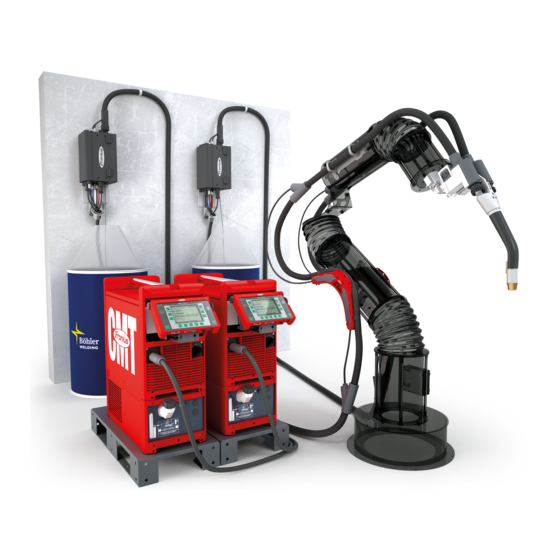
Fronius TWIN Push Tandem Welding System Manuals
Manuals and User Guides for Fronius TWIN Push Tandem Welding System. We have
2
Fronius TWIN Push Tandem Welding System manuals available for free PDF download: Operating Instructions Manual
Fronius TWIN Push Operating Instructions Manual (180 pages)
Brand:
Fronius
| Category:
Welding System
| Size: 21 MB
Table of Contents
Table of Contents
3
Safety Instructions
8
Explanation of Safety Instructions
8
General
8
Intended Use
9
Environmental Conditions
9
Obligations of the Operating Company
9
Obligations of Personnel
9
Grid Connection
10
Personal Protection and Protection of Others
10
Danger from Toxic Gases and Vapors
10
Danger from Flying Sparks
11
Risks from Grid Current and Welding Current
11
Stray Welding Currents
13
EMC Device Classifications
13
EMC Measures
13
EMF Measures
14
Particular Hazard Areas
14
Requirement for the Shielding Gas
15
Danger from Shielding Gas Cylinders
15
Danger Posed by Shielding Gas Leak
16
Safety Measures at the Setup Location and During Transport
16
Safety Measures in Normal Operation
17
Maintenance and Repair
17
Safety Inspection
18
Disposal
18
Safety Symbols
18
Data Backup
18
Copyright
18
General Information
19
General
21
Application Areas
21
Requirements
22
TWIN Push Minimum Equipment
22
TWIN Push/Pull Minimum Equipment
23
TWIN CMT Minimum Equipment
24
Mechanical Requirements
25
Electrical Requirements
25
Software Requirements
25
Dimensioning of the Robot
25
Measures to Increase System Availability
25
Ground Connection
26
Note about the Wirefeed
27
Functional Principle
28
Operating Principle
28
Lead Power Source and Trail Power Source
28
System Configurations
29
TWIN Push System Overview
29
TWIN Push/Pull, CMT System Overview
30
More Configuration Options
31
System Components
33
WF 30I R /TWIN
35
Device Concept
35
Intended Use
35
Warning Notices on the Device
36
Description of the Warnings on the Device
38
Interconnecting Hosepack
40
Torch Hosepack
41
General
41
Scope of Supply
41
Crashbox
42
General
42
Note on the Correct Operation of Crashboxes
42
Note on the Repair of Crashboxes
42
Also Required for the Installation
43
Scope of Supply
43
Scope of Supply Clamp System (TWIN Push)
44
Scope of Supply Index Disk (TWIN Push)
44
Scope of Supply Drive Unit Support (TWIN Push/Pull, CMT)
44
Robot Welding Torch
45
Robot Welding Torches
45
MTB 2X500I R - Contact Tip Tilt Angle
46
TWIN-MTB Single Adapter
47
Welding Technology Aspects
49
Welding Technology Aspects
51
Shielding Gases for TWIN Welding Processes
51
Conducting R/L Comparison
51
Work Angle of the Welding Torch
52
Stick out
52
Application Recommendations for the Tilt Angles of the Contact Tips
53
Welding Start Sequence for CMT TWIN
54
TWIN Operating Mode
54
TWIN Characteristics
55
General
55
Available TWIN Characteristics
56
Slaghammer
60
TWIN Welding Processes
61
TWIN Welding Processes - Overview
61
Symbols
61
Pmc Twin/Pmc Twin
62
Pcs Twin / Pcs Twin
63
Pmc Twin / Cmt Twin
64
Cmt Twin / Cmt Twin
64
Single Wire (with a TWIN Welding Torch):Pmc/Pulse/Lsc/Standard/Cmt
65
TWIN Process Parameters
67
Trail Ignition Delay
67
Pulse Synchronization Ratio
68
Lead/Trail Phase Shift
69
TWIN Synchropulse
70
Synchropulse Welding
70
TWIN Push Welding Parameter Standard Values
71
Standard Values for Fillet Welds, Welding Position PA
71
Standard Values for Fillet Welds, PB Welding Position
73
TWIN Push/Pull Welding Parameter Standard Values
75
Standard Values for Fillet Welds, PB Welding Position
75
Standard Values for Lap Joints, Welding Position PB
76
TWIN CMT Welding Parameter Standard Values
77
Standard Values for Fillet Welds, PB Welding Position
77
Standard Values for Lap Joints, Welding Position PB
78
Operating Controls, Connections and Mechanical Components
79
WF 30I R /TWIN
81
Safety
81
Wirefeeder Front
81
Wirefeeder Side
82
Function of the Gas-Test, Wire-Return, and Wire-Threading Buttons
83
Wirefeeder Rear
85
MHP 2X450I RD/W/FSC Incl. WF 60I TWIN Drive /W
86
Safety
86
MHP 2X450I RD/W/FSC Incl. WF 60I TWIN Drive /W - Mechanical Components
86
MHP 2X450I RD/W/FSC Incl. WF 60I TWIN Drive /W - Control Panel
87
Interconnecting Hosepack
89
Interconnecting Hosepack-Connections
89
TWIN-MTB Single Adapter
90
TWIN-MTB Single Adapter - Connectors
90
Installing the System Components - TWIN Push
91
Safety-Installation and Commissioning
93
Safety
93
Insulated Guiding of the Wire Electrode to the Wirefeeder
94
Before Installation and Initial Operation
95
Setup Regulations
95
Installation - Overview
95
Install TWIN Wirefeeder and Accessories on the Robot
97
Installing the Wirefeeder on the Robot
97
Installing the Side Holders for the Interconnecting Hosepacks on the Robot
98
Lay, Install and Connect Interconnecting Hosepacks
99
Connecting the Interconnecting Hosepacks to the Wirefeeder
99
Install Crashbox, Torch Hosepack and TWIN Welding Torch
101
Mounting the Crashbox /I on the Robot
101
Mounting the Crashbox /I Dummy on the Robot
102
Installing the Inner Liner in the Torch Hosepack
103
Installing the Torch Hosepack
104
Mounting the Torch Body on the TWIN Torch Hosepack
107
Installing the Torch Body Coupling
107
Checking the Function of the Torch Body Coupling
108
Installing the System Components - TWIN Push/Pull, CMT
111
Safety-Installation and Commissioning
113
Safety
113
Insulated Guiding of the Wire Electrode to the Wirefeeder
114
Before Installation and Initial Operation
115
Setup Regulations
115
Installation - Overview of TWIN Push/Pull, CMT
116
Mounting the Balancer Mounting on the Y-Piece
119
Mounting the Support Y-Piece on the Robot
120
Installing the Side Holder on the Robot
121
Installing Wire Buffers on the Robot
122
TWIN-CMT - Installing Wire Buffers on the Robot
122
Install Crashbox, Torch Hosepack and TWIN Welding Torch
124
Mounting the Crashbox /D TWIN on the Robot
124
Mounting the Crashbox TWIN Drive /I Dummy on the Robot
125
Installing the Torch Hosepack with TWIN Drive Unit
126
Connecting the Torch Hosepack to the Wirefeeder
129
Installing Anti-Kink Protection Rings
129
Mounting the Torch Body on the TWIN Drive Unit
131
Fitting the Wirefeeding Hoses and Inner Liners
132
Inserting the Inner Liner into the Torch Hosepack
132
Preparing the TWIN Drive Unit for Operation
133
General
133
Basic Kits Overview
133
Inserting/Changing the Feed Rollers on the TWIN Drive Unit
133
Connecting Wirefeeding Hoses
135
Installing and Preparing Other System Components, Commissioning
137
Installing the Robot Welding Torch
139
Inserting Steel Inner Liner into the Torch Body
139
Inserting Plastic Inner Liner into the Torch Body
140
Installing Wear Parts in the TWIN Welding Torch
142
Inserting the Inner Liner in the TWIN-MTB Single Adapter
143
Preparing TWIN Wirefeeder for Operation
145
Inserting/Changing Feed Rollers
145
Connecting Wirefeeding Hoses
146
Wire Straightener
146
Lay, Install and Connect Interconnecting Hosepacks
147
Connecting Interconnecting Hosepacks to the Robot Wirefeeders
147
Connect TWIN Controller
149
Connect the TWIN Controller with the Power Sources and Connect Interconnecting
149
Hosepack
149
Connecting the TWIN Controller to the Robot Controls
149
Connecting the Protective Gas Shield and Grounding Cable
150
Connecting Protective Gas Shield
150
Connecting the Return Lead Cable
150
Commissioning
151
Threading the Wire Electrode
151
Setting the Contact Pressure
152
Threading the Wire Electrode
152
Setting the Contact Pressure on the TWIN Drive Unit
153
Requirements
153
Commissioning - Start of Welding
153
Troubleshooting, Maintenance, and Disposal
155
Troubleshooting
157
Safety
157
Displayed Error Codes
160
Service, Maintenance and Disposal
162
General
162
Safety
162
At Every Start-Up
162
Weekly
163
Monthly
163
Every 6 Months
163
Disposal
163
Technical Data
165
TWIN Wirefeeder
167
WF 30I R /TWIN
167
Robot Welding Torch
168
MTB 900I R
168
MTB 2X500I R
168
MTB 2X500I R - Dimensions Depending on Contact Tip Tilt Angle
168
Water-Cooled Robot Welding Torches
170
Torch Hosepack
171
MHP 2X500I R/W/FSC
171
MHP 2X450I RD/W/FSC Incl. WF 60I TWIN Drive /W
171
Interconnecting Hosepacks
173
HP 70I
173
Advertisement
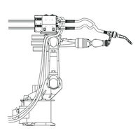
Fronius TWIN Push Operating Instructions Manual (160 pages)
TPS/i Robotics welding system
Brand:
Fronius
| Category:
Welding System
| Size: 24 MB
Table of Contents
Table of Contents
3
Safety Instructions
7
Explanation of Safety Instructions
7
General
7
Intended Use
7
Environmental Conditions
8
Obligations of the Operating Company
8
Obligations of Personnel
8
Grid Connection
8
Personal Protection and Protection of Others
9
Danger from Toxic Gases and Vapors
9
Danger from Flying Sparks
10
Risks from Grid Current and Welding Current
10
Stray Welding Currents
11
EMC Device Classifications
12
EMC Measures
12
EMF Measures
13
Particular Hazard Areas
13
Requirement for the Shielding Gas
14
Danger from Shielding Gas Cylinders
14
Danger Posed by Shielding Gas Leak
15
Safety Measures at the Setup Location and During Transport
15
Safety Measures in Normal Operation
15
Maintenance and Repair
16
Safety Inspection
16
Disposal
16
Safety Symbols
17
Data Backup
17
Copyright
17
General Information
19
General
21
Application Areas
21
Requirements
22
System Requirements and Minimum Equipment TWIN Push
22
System Requirements and Minimum Equipment TWIN Push/Pull
22
System Requirements and Minimum Equipment TWIN CMT
23
Mechanical Requirements
24
Electrical Requirements
24
Software Requirements
24
Dimensioning of the Robot
24
Measures to Increase System Availability
24
Ground Connection
25
Note about the Wirefeed
25
Functional Principle
26
Operating Principle
26
Lead Power Source and Trail Power Source
26
System Configurations
27
TWIN Push System Overview
27
TWIN Push/Pull, CMT System Overview
28
System Components
31
WF 30I R /TWIN
33
Device Concept
33
Intended Use
33
Warning Notices on the Device
34
Description of the Warnings on the Device
36
Interconnecting Hosepack
38
Torch Hosepack
39
General
39
Scope of Supply
39
Crashbox
40
General
40
Also Required for the Installation
40
Scope of Supply
41
Clamp System Scope of Supply
41
Robot Welding Torch
42
Safety
42
Tilt Angle of the Contact Tips
43
Welding Technology Aspects
45
Welding Technology Aspects
47
Shielding Gases for TWIN Welding Processes
47
Conducting R/L Comparison
47
Work Angle of the Welding Torch
48
Stick out
48
Welding Start Sequence for CMT TWIN
49
TWIN Mode
49
TWIN Characteristics
50
General
50
Available TWIN Characteristics
50
TWIN Welding Processes
52
TWIN Welding Processes - Overview
52
Symbols
52
Pmc Twin / Pmc Twin
53
Pcs Twin / Pcs Twin
54
Pmc Twin/Cmt Twin
55
Cmt Twin/Cmt Twin
55
Single Wire (with a TWIN Welding Torch):Pmc/Pulse/Lsc/Standard/Cmt
56
TWIN Process Parameters
58
Pulse Synchronization Ratio
58
Lead/Trail Phase Shift
59
Trail Ignition Delay
59
Welding Parameter Standard Values for Fillet Welds
61
Standard Values for Welding Position PA
61
Standard Values for Welding Position PB
62
Operating Controls, Connections and Mechanical Components
65
WF 30I R /TWIN
67
Safety
67
Wirefeeder Front
67
Wirefeeder Side
68
Function of the Gas-Test, Wire-Return and Wire Threading Buttons
69
Wirefeeder Rear
70
HP 70I, HP PC Cable HD
70
MHP 2X450I RD/W/FSC Incl. WF 60I TWIN Drive /W
71
Safety
71
MHP 2X450I RD/W/FSC Incl. WF 60I TWIN Drive /W - Mechanical Components
71
MHP 2X450I RD/W/FSC Incl. WF 60I TWIN Drive /W - Control Panel
72
Interconnecting Hosepack
73
Interconnecting Hosepack-Connections
73
Installation and Commissioning - TWIN Push
75
Safety-Installation and Commissioning
77
Safety
77
Insulated Guiding of the Wire Electrode to the Wirefeeder
78
Before Installation and Initial Operation
79
Setup Regulations
79
Installation - Overview
79
Install TWIN Wirefeeder and Accessories on the Robot
81
Installing the Wirefeeder on the Robot
81
Installing the Side Holders for the Interconnecting Hosepacks on the Robot
82
Lay, Install and Connect Interconnecting Hosepacks
83
Connecting the Interconnecting Hosepacks to the Wirefeeder
83
Connect the Interconnecting Hosepacks to the Power Source, Cooling Unit and TWIN Controller
84
Connect TWIN Controller
85
Connect the TWIN Controller with the Power Sources and Connect Interconnecting Hosepack
85
Connecting the TWIN Controller to the Robot Controls
85
Install Crashbox, Torch Hosepack and TWIN Welding Torch
86
Mounting the Crashbox /I on the Robot
86
Mounting the Crashbox /I Dummy on the Robot
87
Installing the Inner Liner in the Torch Hosepack
88
Install the Torch Hosepack
90
Prepare Torch Body with Steel Inner Liner
91
Installing Wearing Parts in the TWIN Welding Torch
93
Install the Torch Body Coupling
94
Checking the Function of the Torch Body Coupling
95
Connecting the Protective Gas Shield and Grounding Cable
97
Connecting Protective Gas Shield
97
Connect the Grounding Cable
97
Preparing TWIN Wirefeeder for Operation
98
General
98
Inserting/Changing Feed Rollers
98
Connecting Wirefeeding Hoses
99
Threading the Wire Electrode
99
Setting the Contact Pressure
101
Wire Straightener
101
Commissioning
102
Requirements
102
Commissioning - Start of Welding
102
Installation and Commissioning - TWIN Push/Pull, CMT
103
Safety-Installation and Commissioning
105
Safety
105
Insulated Guiding of the Wire Electrode to the Wirefeeder
106
Before Installation and Initial Operation
107
Setup Regulations
107
Installation - Overview of TWIN Push/Pull, CMT
108
Mounting the Balancer Mounting on the Y-Piece
111
Mounting the Support Y-Piece on the Robot
112
Installing the Side Holder on the Robot
113
Installing Wire Buffers on the Robot
114
TWIN-CMT - Installing Wire Buffers on the Robot
114
Lay, Install and Connect Interconnecting Hosepacks
116
Connecting Interconnecting Hosepacks to the Robot Wirefeeders
116
Connect the Interconnecting Hosepacks to the Power Source, Cooling Unit and TWIN Controller
117
Connect TWIN Controller
118
Connect the TWIN Controller with the Power Sources and Connect Interconnecting Hosepack
118
Connecting the TWIN Controller to the Robot Controls
118
Install Crashbox, Torch Hosepack and TWIN Welding Torch
119
Mounting the Crashbox /I on the Robot
119
Mounting the Crashbox /I Dummy on the Robot
120
Installing the Torch Hosepack with TWIN Drive Unit
121
Connecting the Torch Hosepack to the Wirefeeder
123
Installing Anti-Kink Protection Rings
124
Prepare Torch Body with Steel Inner Liner
125
Installing Wearing Parts in the TWIN Welding Torch
127
Mounting the Torch Body on the TWIN Drive Unit
127
Mounting the Torch Body Coupling on the TWIN Drive Unit
128
Checking the Function of the Torch Body Coupling
129
Fitting the Wirefeeding Hoses and Inner Liners
131
Inserting the Inner Liner into the Torch Hosepack
131
Connecting the Protective Gas Shield and Grounding Cable
132
Connecting Protective Gas Shield
132
Connect the Grounding Cable
132
Preparing the TWIN Drive Unit for Operation
133
General
133
Inserting/Changing the Feed Rollers on the TWIN Drive Unit
133
Connecting Wirefeeding Hoses
134
Threading the Wire Electrode
134
Setting the Contact Pressure
135
Commissioning
136
Requirements
136
Commissioning - Start of Welding
136
Troubleshooting, Maintenance, and Disposal
137
Troubleshooting
139
Safety
139
Displayed Error Codes
142
Service, Maintenance and Disposal
144
General
144
Safety
144
During each Start-Up
144
Monthly
144
Every 6 Months
145
Disposal
145
Technical Data
147
TWIN Wirefeeder
149
WF 30I R /TWIN
149
Robot Welding Torch
150
MTB 2X500I R
150
Dimensions Depend on the Contact Tip Tilt Angle
150
Water-Cooled Robot Welding Torches
152
Torch Hosepack
154
MHP 2X500I R/W/FSC
154
MHP 2X450I RD/W/FSC Incl. WF 60I TWIN Drive /W
154
Interconnecting Hosepacks
156
HP 70I
156
Crashbox /I XXL
157
Crashbox /I XXL - Technical Data & Triggering Torques and Weight-Distance Diagram
157
Advertisement
Related Products
Fronius TWIN Push/Pull
Fronius Robacta Twin 500
Fronius Robacta Twin 600
Fronius Robacta Twin 900
Fronius TransPocket 3500 Comfort
Fronius TPS 3200
Fronius TTG 135
Fronius TTG 180
Fronius THP 120 - 300 SH
Fronius TPS/i COMPACT
Fronius Categories
Inverter
Welding System
Welding Accessories
Battery Charger
Measuring Instruments
More Fronius Manuals
Login
Sign In
OR
Sign in with Facebook
Sign in with Google
Upload manual
Upload from disk
Upload from URL