
Related Manuals for Advantech IDK-1107WR-50WVB1


Summary of Contents for Advantech IDK-1107WR-50WVB1
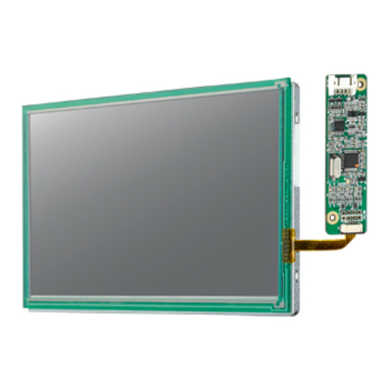
- Page 1 User Manual IDK-1107WR-50WVB1 7" WVGA Industrial Display Kit with 4-Wire Resistive Touch Solution...
- Page 2 No part of this manual may be reproduced, copied, translated or transmitted in any form or by any means without the prior written permission of Advantech Co., Ltd. Information provided in this manual is intended to be accurate and reliable. How- ever, Advantech Co., Ltd.
- Page 3 Because of Advantech’s high quality-control standards and rigorous testing, most of our customers never need to use our repair service. If an Advantech product is defec- tive, it will be repaired or replaced at no charge during the warranty period. For out- of-warranty repairs, you will be billed according to the cost of replacement materials, service time and freight.
- Page 4 IDK-1107WR-50WVB1 User Manual...
-
Page 5: Table Of Contents
Touch Screen Connector, JP2 Pins, and Signal Descriptions ..20 3.4.4 Physical Dimensions..............21 Figure 3.2 Physical Dimensions ..........21 Appendix A LCD Optical Characteristics .....23 LCD Module Optical Characteristics ............24 Table A.1: Optical Characteristics..........24 Appendix B Safety Precautions ......27 Safety Precautions .................. 28 IDK-1107WR-50WVB1 User Manual... - Page 6 IDK-1107WR-50WVB1 User Manual...
-
Page 7: Chapter 1 Overview
Chapter Overview... -
Page 8: General Description
General Description Advantech’s IDK-1107WR-50WVB1 features a 7" industrial grade LCD display with 4-wire resistive touch. Specifications 1.2.1 LCD Panel Display Size: 7", 16:9 Resolution: 800 x 480 Display Mode: Normally Black (IPS base) Viewing Angle (Horizontal/Vertical): 178°/178°... -
Page 9: Mechanical Characteristics
Mechanical Characteristics Front View Unit: mm IDK-1107WR-50WVB1 User Manual... - Page 10 Rear View Tolerance: +/- 0.5mm IDK-1107WR-50WVB1 User Manual...
-
Page 11: Chapter 2 Lcd Display
Chapter LCD Display... -
Page 12: Functional Block Diagram
Permanent damage to the device may occur if maximum values are exceeded. Operation should be restricted to the conditions described under Normal Operating Conditions. Note! Specified values are for input pin of LED light bar at Ta=25 ±2 °C (77 ± 3.6 °F) . IDK-1107WR-50WVB1 User Manual... -
Page 13: Lcd Electronics Specification
(3)c Power Consumption PLCD 0.48 0.73 LVDS Differential Input Voltage LVDS Common Input Voltage LVDS Terminating Resistor Note (1) The ambient temperature is Ta = 25 ± 2 °C (77 ± 3.6 °F) Note (2) Measurement conditions: IDK-1107WR-50WVB1 User Manual... - Page 14 Note (3) The specified power supply current is under the following conditions — Vcc = 3.3V, Ta = 25 ±2 °C (77 ± 3.6 °F), fv = 60 Hz. Refer to the diagram below for power dissipation patterns IDK-1107WR-50WVB1 User Manual...
-
Page 15: Backlight Unit
Ta = 25 ± 2 °C (77 ± 3.6 °F) operating conditions. It specifies Duty at 100% until the brightness becomes ≤ 50% of its original value. Operating the LED solution in high tem- perature environments will reduce the products lifespan and lead to color shift. IDK-1107WR-50WVB1 User Manual... -
Page 16: Input Terminal Pin Assignment
Positive of clock - Ground RX3- Negative transmission data of pixel RX3+ Positive transmission data of pixel Ground LVDS 6/8 bit select function control, SEL6/8 Low: 6 bit Input Mode High or NC: 8bit Input Mode Ground Ground IDK-1107WR-50WVB1 User Manual... -
Page 17: Color Data Input Assignment
B6 B5 B4 B3 B2 B1 B0 Black Green Blue Basic Colors Cyan Magenta Yellow White Red(0) / Dark Red(1) Red(2) Gray Scale Red(253) 1 Red(254) 1 Red(255) 1 Green(0) / Dark Green(1) Green(2) Gray Scale Green Green (253) Green (254) Green (255) IDK-1107WR-50WVB1 User Manual... -
Page 18: Interface Timing
-0.02*Tc - 0.02*Tc Skew LVDS Clock Spread Spectrum Fclkin_mod FC*98% - FC*102% MHz Modulation Range Spread Spectrum Modulation Frequency Frame Rate Fr Tv=Tvd+Tvb Total Vertical Active Display Term Display Blank Total Th=Thd+Thb Horizontal Active Display Term Display Blank IDK-1107WR-50WVB1 User Manual... - Page 19 Note (2) The Tv (Tvd+Tvb) must be an integer; otherwise, this module will oper- ate abnormally. INPUT SIGNAL TIMING DIAGRAM Note (3) The input clock cycle-to-cycle jitter is defined in the following figures. Trcl = I T1 – TI IDK-1107WR-50WVB1 User Manual...
- Page 20 Note (4) Input Clock to data skew is defined in the figures below. Note (5) The SSCG (Spread spectrum clock generator) is defined in the figure below. IDK-1107WR-50WVB1 User Manual...
-
Page 21: Power On/Off Sequence
Note (3) The backlight converter power must be turned on after the power supply for the logic and the interface signal to be valid. The backlight converter power must be turned off before the power supply for the logic and the interface signal to be invalid. IDK-1107WR-50WVB1 User Manual... - Page 22 IDK-1107WR-50WVB1 User Manual...
-
Page 23: Chapter 3 Touch Controller
Chapter Touch Controller... -
Page 24: Touch Controller Characteristics
Touch Controller Characteristics Advantech ETM-RES05C touch control board is the ultimate combo board. This touch panel controller provides optimum performance to analog resistive touch pan- els for 4-wire models. It communicates with PC systems directly using USB and RS- 232 connectors. In addition, the touch panel driver emulates mouse left and right but- ton functions. -
Page 25: Pin Assignment And Description
Power Ground Ground USB D+ Serial Port USB D- Serial Port Signal DB-9 pin # RS-232 pin # Sourced by Signal Description Name ctlr serial data from controller to host host serial data from host to controller IDK-1107WR-50WVB1 User Manual... -
Page 26: Touch Screen Connector, Jp2 Pins, And Signal Descriptions
The Touch Screen connector, JP2, is a FFC/FPC SMD 1.0 mm 4-pin 90° degree, female type connector. The pins numbers are demonstrated in the table below. TS4 Pin # Signal Name Signal Description Bottom Left Right 4-Wire touch screen ZIF connector 4-Wire screen viewed from cover sheet side IDK-1107WR-50WVB1 User Manual... -
Page 27: Physical Dimensions
3.4.4 Physical Dimensions Figure 3.2 Physical Dimensions IDK-1107WR-50WVB1 User Manual... - Page 28 IDK-1107WR-50WVB1 User Manual...
-
Page 29: Appendix Alcd Optical Characteristics
Appendix LCD Optical Characteristics... -
Page 30: Lcd Module Optical Characteristics
CR ≧ 10 Luminance Uniformity White x 0.313 Color Coordinates Typ – Typ + (CIE 1931) 0.05 0.05 White y 0.315 Rising Response Time [ms] Falling White Luminance [cd/m Contrast Ratio Note! Viewing angle definition Note! 5-points position IDK-1107WR-50WVB1 User Manual... - Page 31 In order to stabilize the luminance, the measurement should be executed after lighting the backlight for 20 minutes in a stable, windless and dark room. Note! Response time definition IDK-1107WR-50WVB1 User Manual...
- Page 32 Contrast Ratio (CR) = L255 / L0 L255: Luminance of gray level 255 L 0: Luminance of gray level 0 CR = CR (5) CR (X) is corresponding to the Contrast Ratio of the point X (See Figure IDK-1107WR-50WVB1 User Manual...
-
Page 33: Appendix B Safety Precautions
Appendix Safety Precautions... -
Page 34: Safety Precautions
A small amount of materials with no flammability grade are used in the LCD module. The LCD module should be supplied by power compliant with the requirements of Limited Power Source (IEC60950 or UL1950), or be applied exempt thereof. IDK-1107WR-50WVB1 User Manual... - Page 35 No part of this publication may be reproduced in any form or by any means, electronic, photocopying, recording or otherwise, without prior written permis- sion from the publisher. All brand and product names are trademarks or registered trademarks of their respective companies. © Advantech Co., Ltd. 2021...
Need help?
Do you have a question about the IDK-1107WR-50WVB1 and is the answer not in the manual?
Questions and answers