Table of Contents
Advertisement
Quick Links
Advertisement
Table of Contents

Subscribe to Our Youtube Channel
Related Manuals for Advantech IDK-1115R-40XGC2E


Summary of Contents for Advantech IDK-1115R-40XGC2E
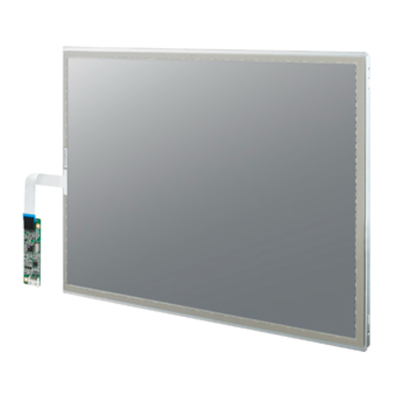
- Page 1 User Manual IDK-1115R-40XGC2E TFT-LCD 15" XGA (LED Backlight)
- Page 2 No part of this manual may be reproduced, copied, translated or transmitted in any form or by any means without the prior written permission of Advantech Co., Ltd. Information provided in this manual is intended to be accurate and reliable. How- ever, Advantech Co., Ltd.
- Page 3 Whether your new Advantech equipment is destined for the labo- ratory or the factory floor, you can be assured that your product will provide the reliability and ease of operation for which the name Advantech has come to be known.
- Page 4 Because of Advantech’s high quality-control standards and rigorous testing, most of our customers never need to use our repair service. If an Advantech product is defec- tive, it will be repaired or replaced at no charge during the warranty period. For out- of-warranty repairs, you will be billed according to the cost of replacement materials, service time and freight.
-
Page 5: Table Of Contents
Contents Chapter Overview..........1 General Description .................. 2 Display Characteristics................2 Mechanical Specification................2 Mechanical Dimension ................3 Absolute Maximum Ratings ..............4 1.5.1 Absolute Ratings of Environment..........4 1.5.2 Electrical Absolute Ratings ............4 Block Diagram................... 5 Figure 1.1 TFT LCD module ............5 Chapter Electrical Characteristics....7... - Page 6 Handling Precautions................32 IDK-1115R User Manual...
-
Page 7: Chapter 1 Overview
Chapter Overview... -
Page 8: General Description
General Description IDK-1115R-K2XGA1E is a Color Active Matrix Liquid Crystal Display composed of a TFT-LCD panel, a driver circuit, and backlight system. The screen format is intended to support the XGA (1024(H) x 768(V)) screen and 16.2M/262k colors (RGB). All input signals are LVDS interface compatible. -
Page 9: Mechanical Dimension
Mechanical Dimension IDK-1115R User Manual... -
Page 10: Absolute Maximum Ratings
Absolute Maximum Ratings 1.5.1 Absolute Ratings of Environment Value Item Symbol Unit Note Min. Max. ° Operating Ambient Temperature ° Storage Temperature Note: (1) Temperature and relative humidity range is shown in the figure below (2) 90%RH Max. (Ta ≤ 40° (3) Wet-bulb temperature should be 39°... -
Page 11: Block Diagram
Block Diagram Figure 1.1 TFT LCD module IDK-1115R User Manual... - Page 12 IDK-1115R User Manual...
-
Page 13: Chapter 2 Electrical Characteristics
Chapter Electrical Characteristics... -
Page 14: Tft Lcd Module
TFT LCD Module Value Parameter Symbol Unit Note Min. Typ. Max. Power Supply Voltage Ripple Voltage mVp-p Rush Current RUSH White (3)a Power Supply Cur- rent Black (3)b Differential Input “H” Level Voltage for LVDS Receiver “L” Level -100 Threshold Terminating Resistor Note1: The module should be always operated within above ranges Note2: Measurement Conditions:... -
Page 15: Backlight Unit
Backlight Unit Value Parameter Symbol Unit Note Min. Typ. Max. Converter Power Supply Voltage 10.8 12.0 13.2 Converter Power Supply Current 0.73 0.83 @ Vi = Backlight Power Consumption 8.76 @ Vi = Backlight on EN Control Level Backlight off PWM High Level PWM Control Level... - Page 16 IDK-1115R User Manual...
-
Page 17: Chapter 3 Input Terminal Pin Assignment
Chapter Input Terminal Pin Assignment... -
Page 18: Tft Lcd Module
TFT LCD Module Table 3.1: Symbol Description Pin No. Symbol Description Polarity Note Power Supply, 3.3V(typical) Power Supply, 3.3V(typical) Ground No Connection RX0- LVDS Differential Data Input Negative RX0+ LVDS Differential Data Input Positive Ground RX1- LVDS Differential Data Input Negative RX1+ LVDS Differential Data Input... -
Page 19: Color Data Input Assignment
Color Data Input Assignment The brightness of each primary color (red, green and blue) is based on the 8-bit gray scale data input for the color. The higher the binary input the brighter the color. The table below provides the assignment of color versus data input. Color Data Signal Green... - Page 20 IDK-1115R User Manual...
-
Page 21: Chapter 4 Interface Timing
Chapter Interface Timing... -
Page 22: Input Signal Timing Specifications
Input Signal Timing Specifications The input signal timing specifications are shown as the following table and timing dia- gram: Signal Item Symbol Min. Typ. Max. Unit Note DCLK Pixel Clock Vertical Total Time 1200 Vertical Address Time Horizontal Total Time 1140 1344 1600... -
Page 23: Power On/Off Sequence
Power On/Off Sequence To prevent a latch-up or DC operation of LCD assembly, the power on/off sequence should be as in the diagram below. Note 1 Please avoid floating state of interface signal at invalid period Note 2 When the interface signal is invalid, be sure to pull down the power supply of LCD VCC to 0 V. - Page 24 IDK-1115R User Manual...
-
Page 25: Chapter 5 Touch Screen
Chapter Touch Screen... -
Page 26: Touch Characteristics
Touch Characteristics 5-wire analog resistance type touch panels are used with flat displays like LCDs. Once touched by stylus or finger, the circuit sends coordinate points to the PC from voltage contact points. Optical Characteristics Item Specification Remarks ± TRANSPARENCY BYK-Gardner ±... -
Page 27: General Specification
General Specification Item Specification ± ± Frame size 322.00 0.30 X 245.50 0.30 mm ± ± View Area 309.00 0.30 X 233.50 0.20 mm ± ± Active Area 303.00 0.30 X 227.50 0.20 mm ± Total Thickness 2.20 0.20 mm ±... - Page 28 IDK-1115R User Manual...
-
Page 29: Chapter 6 Touch Controller
Chapter Touch Controller... -
Page 30: Touch Controller Characteristics
Advantech ETM-RES04C Touch Control Board, the ultimate combo board. This touch panel controller provides the optimistic performance of your analog resistive touch panels for 5 wire models. It communicates with your PC system directly through USB and RS-232 connectors. You can see how superior the design is in sen- sitivity, accuracy and friendly operation. -
Page 31: Environmental Features
6.1.2 Environmental Features Reliability MTBF is 200,000 hours Temperature Ranges Operating : -25°C ~ 85°C Storage: -25°C ~ 85°C Relative Humidity 95% at 60°C, RH Non-condensing Acquired RoHS certificate Requlatory FCC-B, CE approvals Dimension: 75 mm x 20 mm x 10 mm Pin Assignment and Description 6.2.1 Connector and LED Location... -
Page 32: Combo Interface Connector, Jp1, Pins And Signal Descriptions 25 Figure 6.1 Board Mounted Header
Figure 6.1 Board mounted header 6.2.3 Touch Screen Connector, JP2, Pins and Signal Descriptions The Touch Screen connector, JP2, is a single row by 2.54mm 5-pins 90 degree, male type connector. The pins are numbered as in the table below. JP2 Pin # Signal Name Signal Description... - Page 33 Appendix Optical Characteristics...
-
Page 34: Test Conditions
Test Conditions Item Symbol Value Unit ± Ambient Temperature Ta °C ± Ambient Humidity Supply Voltage Input Signal According to typical value in "3. ELECTRICAL CHARACTERISTICS" Converter Voltage Converter Duty 100% Optical Specifications The relative measurement methods of optical characteristics are shown below. The following items should be measured under the test conditions and stable environ- ment shown in Note 5. - Page 35 , θ Note 1 Definition of Viewing Angle (θ Note 2 Definition of Contrast Ratio (CR): The contrast ratio can be calculated by the following expression. Contrast Ratio (CR) = L255 / L0 L255: Luminance of gray level 255 L0: Luminance of gray level 0 CR = CR (5) CR (X) is corresponding to the Contrast Ratio of the point X at Figure in Note Note 3 Definition of Response Time (TR, TF):...
- Page 36 Note 5 Measurement Setup: The LCD module should be stabilized at given temperature for 20 minutes to avoid abrupt temperature change during measuring. In order to stabilize the luminance, the measurement should be executed after lighting Backlight for 20 minutes in a windless room. Note 6 Definition of White Variation (δW): Measure the luminance of gray level 255 at 5 points...
- Page 37 Appendix Handling Precautions...
- Page 38 Handling Precautions The optical characteristics are measured under stable conditions at 25°C (Room Temperature) Since front polarizer is easily damaged, pay attention not to scratch it. Be sure to turn off power supply when inserting or disconnecting from input con- nector.
- Page 39 No part of this publication may be reproduced in any form or by any means, electronic, photocopying, recording or otherwise, without prior written permis- sion of the publisher. All brand and product names are trademarks or registered trademarks of their respective companies. © Advantech Co., Ltd. 2012...
Need help?
Do you have a question about the IDK-1115R-40XGC2E and is the answer not in the manual?
Questions and answers