
Related Manuals for Advantech IDK-1115WP-45FHA2


Summary of Contents for Advantech IDK-1115WP-45FHA2
- Page 1 User Manual IDK-1115WP-45FHA2 15.6” FHD Industrial Display Kit with Projected Capacitive Touch Solution...
- Page 2 No part of this manual may be reproduced, copied, translated, or transmitted in any form or by any means without the prior written permission of Advantech Co., Ltd. The information provided in this manual is intended to be accurate and reliable.
- Page 3 Product Warranty (2 years) Advantech warrants the original purchaser that each of its products will be free from defects in materials and workmanship for two years from the date of purchase. This warranty does not apply to any products that have been repaired or altered by persons other than repair personnel authorized by Advantech, or products that have been subject to misuse, abuse, accident, or improper installation.
- Page 4 IDK-1115WP-45FHA2 User Manual...
-
Page 5: Table Of Contents
LCD Optical Characteristics .....23 LCD Module Optical Characteristics ............24 Table A.1: Optical Characteristics..........24 Figure A.1 Optical Characteristics..........24 Figure A.2 9-Points Position............25 Figure A.3 Measurement Method..........26 Figure A.4 Response Time Definition ........27 IDK-1115WP-45FHA2 User Manual... - Page 6 Appendix B Safety Precautions......29 Assembly and Handling Precautions ............30 Storage Precautions ................30 Operation Precautions ................30 Safety Precautions.................. 30 IDK-1115WP-45FHA2 User Manual...
-
Page 7: Chapter 1 Overview
Chapter Overview... -
Page 8: Introduction
Introduction The Advantech IDK-1115WP series comes with a 15.6" industrial grade Projected Capacitive touch (PCAP) LCD display. This series PCAP screen leverages low power consumption technology and is ideal for embedded applications that require maxi- mum flexibility for mechanical design. -
Page 9: Mechanical Characteristics
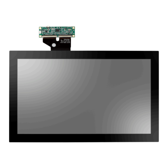
Figure 1.1 LCD Operating Range Mechanical Characteristics Front View Figure 1.2 Front View IDK-1115WP-45FHA2 User Manual... - Page 10 Rear View Figure 1.3 Rear View Touch Control Board Figure 1.4 Touch Control Board Note: Tolerances unless marked are ± 0.5 mm/.01 in IDK-1115WP-45FHA2 User Manual...
-
Page 11: Chapter 2 Lcd Display
Chapter LCD Display... -
Page 12: Functional Block Diagram
Note (1) Permanent damage to the device may occur if maximum values are exceeded. Operation should be restricted to the conditions described under Normal Operating Conditions. Note (2) Specified values are for input pin of LED light bar at Ta= 25 ± 2 °C (75 ± 3.6 °F) IDK-1115WP-45FHA2 User Manual... -
Page 13: Lcd Electronics Specification
(3)c Stripe Power PLCD Watt Consumption LVDS differential input voltage LVDS common input voltage LVDS terminating resistor Note (1) The ambient temperature is Ta = 25 ± 2 °C (75 ± 3.6 °F). Note (2) Measurement Conditions: IDK-1115WP-45FHA2 User Manual... - Page 14 The specified power supply current is under conditions at Vcc = 3.3 V, Ta = 25 ± °C (75 ± 3.6 °F), Fr = 60Hz, for power dissipation check the diagram dis- played below. Note (4) The power consumption is specified at the pattern with the maximum current. IDK-1115WP-45FHA2 User Manual...
-
Page 15: Backlight Unit
Control Level PWM Low 0.15 Level PWM Control Duty Ratio PWM Control Frequency fPWM LED Life 50,000 Time Note (1) LED light bar input voltage and current are measured by utilizing a true RMS multimeter as shown below: IDK-1115WP-45FHA2 User Manual... -
Page 16: Lvds Input Signal Specifications
LVDS Channel O3 Data order LVDS output D7 LVDS Channel E0 Data order LVDS output D18 LVDS Channel E1 Data order LVDS output D26 LVDS Channel E2 Data order LVDS output D23 LVDS Channel E3 Data order IDK-1115WP-45FHA2 User Manual... -
Page 17: Color Data Input Assignment
Red(253) Red(254) Red(255) Green(0) / Dark Green(1) Green(2) Gray Scale Green" Green(253) 0 Green(254) 0 Green(255) 0 Blue(0) / Dark Blue(1) Blue(2) Gray Scale Blue" Blue(253) Blue(254) Blue(255) Note(1)! 0: Low Level Voltage, 1: High Level Voltage IDK-1115WP-45FHA2 User Manual... -
Page 18: Display Timing Specifications
Horizontal Dis- Active play Term Display Blank Th-Thd Th-Thd Note(1)! Because this module is operated by DE only mode, Hsync, and Vsync input signals are ignored. Note(2)! The Tv(Tvd+Tvb) must be integer, otherwise, this module would operate abnormally. IDK-1115WP-45FHA2 User Manual... - Page 19 Note(3)! The input clock cycle-to-cycle jitter is defined in the following figures. Trcl = I T1 - TI . Note(4)! Input Clock to data skew is defined in the following figures. IDK-1115WP-45FHA2 User Manual...
-
Page 20: Power On/Off Sequence
Note(5)! The SSCG (Spread spectrum clock generator) is defined in the following figures. Power On/Off Sequence The power sequence specifications are shown in the following table and diagram. IDK-1115WP-45FHA2 User Manual... - Page 21 Power Sequence. There might be slight electronic noise when LCD is turned off (even backlight unit is also off). To avoid this , we suggest using" Vcc fall- ing timing" to follow "T7 spec". IDK-1115WP-45FHA2 User Manual...
-
Page 22: Pin Description
Positive LVDS differential data input. Channel E2 (even) RXEC- Negative LVDS differential clock input. (even) RXEC+ Positive LVDS differential clock input. (even) RXE3- Negative LVDS differential data input. Channel E3 (even) RXE3+ Positive LVDS differential data input. Channel E3 (even) IDK-1115WP-45FHA2 User Manual... - Page 23 Note(1)! Connector Part No.: I-PEX 20455-040E-76 or equivalent. Note(2)! User's connector Part No.: I-PEX 20453-040T-03 or equivalent. IDK-1115WP-45FHA2 User Manual...
- Page 24 IDK-1115WP-45FHA2 User Manual...
-
Page 25: Chapter 3 Touchscreen & Touch Controller
Chapter Touchscreen & Touch Controller... -
Page 26: Touchscreen
Black border Touch Control Board Advantech’s IDK-1115WP-45FHA2 projected capacitive touch screen adopts a COB (Chip on Board FPC) design with EETI EXC80H84 touch controller. An extra touch control board is required and bundled in this model. This communicates with a PC directly through USB connectors. -
Page 27: Electrical Specifications
Idle Mod : depends on firmware Report rate > 100Hz 3.2.2 Pin Assignment and Description There are 2 x interfaces — USB and I2C (Optional). Connectors and Pin assign- ments are displayed below. Figure 3.1 Connectors and Pin Assignment IDK-1115WP-45FHA2 User Manual... - Page 28 IDK-1115WP-45FHA2 User Manual...
-
Page 29: Appendix Alcd Optical Characteristics
Appendix LCD Optical Characteristics... -
Page 30: Lcd Module Optical Characteristics
CR ≧ 10 Luminance Uniformity White x 0.313 Color coordinates Typ – Typ + (CIE 1931) 0.045 0.045 White y 0.329 Rising Response Time [ms] Falling White Luminance [cd/m Contrast Ratio Figure A.1 Optical Characteristics Note! 9-points position IDK-1115WP-45FHA2 User Manual... - Page 31 The LCD module should be stabilized at a given temperature for 20 min- utes to avoid abrupt temperature changes during measurement. In order to stabilize the luminance, the measurement should be executed after lighting the backlight for 20 minutes in a stable, windless, and dark room. IDK-1115WP-45FHA2 User Manual...
- Page 32 Figure A.3 Measurement Method Note! Definition of response time IDK-1115WP-45FHA2 User Manual...
- Page 33 Contrast Ratio (CR) = L255 / L0 L255: Luminance of gray level 255 L 0: Luminance of gray level 0 CR = CR (5) CR (X) is corresponding to the Contrast Ratio of the point X IDK-1115WP-45FHA2 User Manual...
- Page 34 IDK-1115WP-45FHA2 User Manual...
- Page 35 Appendix Safety Precautions...
- Page 36 If the product will be used in extreme conditions such as those with high tem- peratures, humidity, altitude, or display pattern or operation time etc. We strongly recommend contacting Advantech for application engineering advice. Otherwise, its reliability and functionality is not be guaranteed.
- Page 37 No part of this publication may be reproduced in any form or by any means, electronic, photocopying, recording or otherwise, without prior written permis- sion from the publisher. All brand and product names are trademarks or registered trademarks of their respective companies. © Advantech Co., Ltd. 2022...
Need help?
Do you have a question about the IDK-1115WP-45FHA2 and is the answer not in the manual?
Questions and answers