
Related Manuals for Advantech IDK-1110WP Series


Summary of Contents for Advantech IDK-1110WP Series
- Page 1 User Manual IDK-1110WP Series 10.1” WXGA Industrial Display Kit with Touch Solution...
- Page 2 No part of this manual may be reproduced, copied, translated or transmitted in any form or by any means without the prior written permission of Advantech Co., Ltd. Information provided in this manual is intended to be accurate and reliable. How- ever, Advantech Co., Ltd.
- Page 3 Whether your new Advantech equipment is destined for the labo- ratory or the factory floor, you can be assured that your product will provide the reliability and ease of operation for which the name Advantech has come to be known.
- Page 4 Because of Advantech’s high quality-control standards and rigorous testing, most of our customers never need to use our repair service. If an Advantech product is defec- tive, it will be repaired or replaced at no charge during the warranty period. For out- of-warranty repairs, you will be billed according to the cost of replacement materials, service time and freight.
-
Page 5: Table Of Contents
Contents Chapter Overview..........1 General Description .................. 2 Specifications .................... 2 1.2.1 LCD Panel..................2 1.2.2 Touch Screen................2 1.2.3 Environment.................. 2 LCD Functional Block Diagram ..............3 Figure 1.1 Function block diagram ..........3 Mechanical Characteristics ............... 3 Touch Screen driver.................. 4 Absolute Maximum Ratings .............. -
Page 6: Handling Precautions
Appendix B Handling Precautions ....... 27 Handling Precautions................28 IDK-1110WP User Manual... -
Page 7: Chapter 1 Overview
Chapter Overview... -
Page 8: General Description
General Description The Advantech IDK-1110WP series comes with a 10.1" industrial grade LCD display and project capacitive touch. The series is also available with flexible options for LCD screens enhanced treatment such as Anti-Reflection surface treatment and optical bonding solution. IDK-1110WP series has low power consumption at the typical of 6.18 W. -
Page 9: Lcd Functional Block Diagram
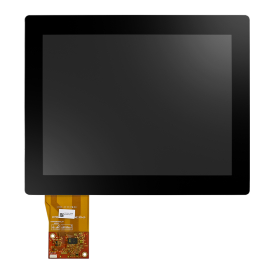
LCD Functional Block Diagram The following diagram shows the functional block of the 10.1 inches Color TFT-LCD Module: Figure 1.1 Function block diagram Mechanical Characteristics Front View IDK-1110WP User Manual... -
Page 10: Touch Screen Driver
Rear View Touch Screen driver Please down load the touchscreen driver from Advantech website. Absolute Maximum Ratings 1.6.1 TFT LCD Module Item Symbol Min. Max. Unit Note Logic/LCD Drive Voltage -0.3 [Volt] 1, 2 1.6.2 Backlight Unit Item Symbol Value... - Page 11 IDK-1110WP User Manual...
- Page 12 IDK-1110WP User Manual...
-
Page 13: Chapter 2 Electrical Characteristics
Chapter Electrical Characteristics... -
Page 14: Tft Lcd Module
TFT LCD Module 2.1.1 Power Specification Input power specifications are as follows: Table 2.1: Power specification Value Parameter Symbol Unit Condition Min. Typ. Max. Logic/LCD Drive [Volt] Voltage Input Current 0.265 0.320 [A] White Pat- tern(VCC=3.3V at 60Hz) VCC Power 0.88 1.15 [Watt]... - Page 15 Note3! The specified power supply current is under the conditions at VDD =3.3V, Ta = 25 ± 2°C, DC Current and fv = 60 Hz, whereas a power dis- sipation check pattern below is displayed. a. White Pattern b. Black Pattern Active Area Active Area IDK-1110WP User Manual...
-
Page 16: Backlight Unit
Backlight Unit Following characteristics are measured under stable condition at 25°C: Table 2.3: Backlight driving conditions Values Item Symbol Unit Condition Min. Typ. Max. Input Voltage 10.8 13.2 [Volt] Input Current 0.45 0.50 @ Vi = 12V (Duty 100%) Power Consumption [Watt] PWM Dimming Frequency [Hz]... - Page 17 Power sequence and control signal timing are shown in the following figure. Note! While the system is turned ON or OFF, the power sequences must fol- low as below descriptions. Turn ON sequence: Vi(+12V) → BLON → E_PWM signal Turn OFF sequence: E_PWM signal → BLON → Vi(+12V) IDK-1110WP User Manual...
- Page 18 IDK-1110WP User Manual...
-
Page 19: Chapter 3 Signal Characteristics
Chapter Signal Characteristics... -
Page 20: Pixel Format Image
Pixel Format Image Following figure shows the relationship between input signal and LCD pixel format. The Input Data Format IDK-1110WP User Manual... -
Page 21: Pin Description
Pin Description The module uses LVDS receivers- I-PEX 20455-040E-12 or Tyco_5-2069716-3. Table 3.1: Pin Description Pin No. Symbol Description VCCS Power Supply +3.3V(typical) VCCS Power Supply +3.3V(typical) VCCS Power Supply +3.3V(typical) L or NC: 8bit Input Mode Data format H: 6bit Input Mode No Connection (Reserve) No Connection (Reserve) No Connection (Reserve) -
Page 22: Interface Timing
Note1! “Low” stands for 0V. “High” stands for 3.3V. “NC” stands for “No Con- nection”. Note1! Interface optional pin has internal scheme as following diagram, Cus- tomer should keep the interface voltage level requirement which includ- ing panel board loading as below. Interface Timing 3.4.1 Timing Characteristics... -
Page 23: Timing Diagram
3.4.2 Timing Diagram Power ON/OFF Sequence To prevent a latch-up or DC operation of LCD assembly, the power on/off sequence should be as the diagram below Note1! Please avoid floating state of interface signal at an invalid period. Note2! When the interface signal is invalid, be sure to bring down the power supply of LCD VCC to 0 V. - Page 24 Note3! The backlight converter power must be turned on after the power supply for the logic and the interface signal to be valid. The backlight converter power must be turned off before the power supply for the logic and the interface signal to be invalid.
-
Page 25: Chapter 4 Touchscreen & Touch Controller
Chapter Touchscreen & Touch Controller... -
Page 26: Touchscreen
Clear Touch Controller Advantech’s IDK-1110WP series projective capacitive touch screen adopts a COF (Chip on FPC) design so an extra touch control board is not required. This communi- cates with a PC system directly through USB connectors. The superior design is sen- sitive, accurate and user friendly. -
Page 27: Pin Assignment And Description
4.2.2 Pin Assignment and Description 4.2.2.1 Connector and LED Location 4.2.2.2 USB interface connector and pin assignment The USB interface connector is a 5-pin and pitch 1.25mm connector. (UTY 1W 1258WOR0-05K) The pins are numbered as shown in the table below. Pin No. - Page 28 IDK-1110WP User Manual...
-
Page 29: Appendix Alcd Optical Characteristics
Appendix LCD Optical Characteristics... -
Page 30: Lcd Module Optical Characteristics
LCD Module Optical Characteristics The optical characteristics are measured under stable conditions at 25°C (Room Temperature): Table A.1: Optical Characteristics Item Conditions Min. Typ. Max. Unit Note Horizontal 80/80 85/85 CR10 Viewing Angle [degree] USB2000 Vertical 80/80 85/85 CR = 10 Luminance 2, 3 Uniformity... - Page 31 Note2 5 points position Note3 5-point luminance uniformity is defined by dividing the maximum luminance values by the minimum test point luminance Minimum [L (1) ~ L (5)] Maximum [L (1) ~ L (5)] Note4 Measurement method The LCD module should be stabilized at given temperature for 20 minutes to avoid abrupt temperature change during measuring.
- Page 32 Note5 Definition of response time The output signals of the photo detector are measured when the input signals are changed from "Full Black" to "Full White" (rising time), and from "Full White" to "Full Black "(falling time), respectively. The response time is an interval between 10% and 90% of amplitudes.
- Page 33 Appendix Handling Precautions...
- Page 34 Handling Precautions The optical characteristics are measured under stable conditions at 25°C (Room Temperature) Since the front polarizer is easily damaged, be very careful not to scratch it. Be sure to turn off the power supply when inserting or disconnecting from the input connector.
- Page 35 No part of this publication may be reproduced in any form or by any means, electronic, photocopying, recording or otherwise, without prior written permis- sion of the publisher. All brand and product names are trademarks or registered trademarks of their respective companies. © Advantech Co., Ltd. 2017...
Need help?
Do you have a question about the IDK-1110WP Series and is the answer not in the manual?
Questions and answers