
Related Manuals for Advantech IDK-1110WR-50WSA1


Summary of Contents for Advantech IDK-1110WR-50WSA1
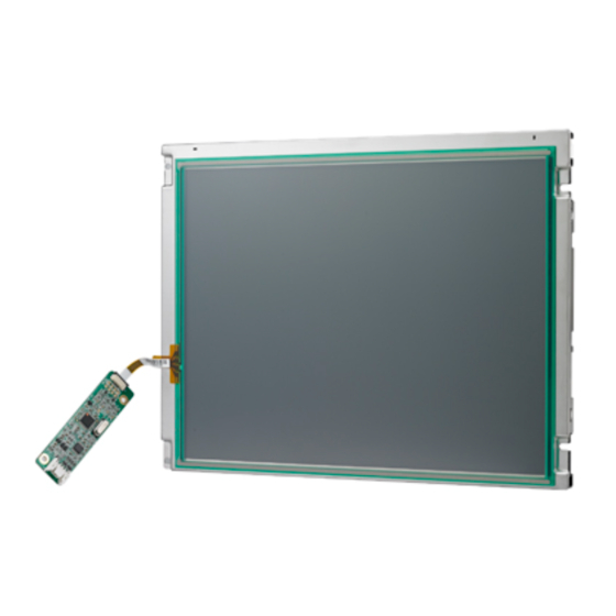
- Page 1 User Manual IDK-1110WR-50WSA1 101" WSVGA Industrial Display Kit with 4-Wire Resistive Touch Solution...
- Page 2 No part of this manual may be reproduced, copied, translated or transmitted in any form or by any means without the prior written permission of Advantech Co., Ltd. Information provided in this manual is intended to be accurate and reliable. How- ever, Advantech Co., Ltd.
- Page 3 Advantech has come to be known. Your satisfaction is our primary concern. Here is a guide to Advantech’s cus- tomer services.
- Page 4 Because of Advantech’s high quality-control standards and rigorous testing, most of our customers never need to use our repair service. If an Advantech product is defec- tive, it will be repaired or replaced at no charge during the warranty period. For out- of-warranty repairs, you will be billed according to the cost of replacement materials, service time and freight.
-
Page 5: Table Of Contents
Contents Chapter Overview..........1 General Description .................. 2 Display Characteristics................2 Display Optical Characteristics ..............3 1.3.1 Measuring Condition ..............3 1.3.2 Measuring Equipment ..............3 Block Diagram................... 5 Figure 1.1 TFT LCD Module ............5 Absolute Maximum Ratings ..............5 1.5.1 Absolute Max Rating.............. - Page 6 LCD EDID ....................24 IDK-1110WR User Manual...
-
Page 7: Chapter 1 Overview
Chapter Overview... -
Page 8: General Description
Industrial Applications. An LED driving board for the back- light unit is included in this panel. IDK-1110WR-50WSA1 uses a built in timing con- troller and LVDS interface. The screen format is intended to support the WSVGA (1024(H) x 600(V)) screen and 262k colors (RGB 6-bits). -
Page 9: Display Optical Characteristics
Display Optical Characteristics The optical characteristics are measured under stable conditions at 25°C (Room Temperature): Values Unit Note Item Symbol Conditions Min. Typ. Max. Viewing Angle degree 1, 2 Response Time TR+TF msec Contrast Ratio Color Chromaticity 0.263 0.313... - Page 10 Note 2: Definition of Contrast Ratio Contrast ratio is calculated with the following formula : Contrast Ratio (CR)=(White) Luminance of ON ÷ (Black) Luminance of OFF Note 3: Definition of Response time: Sum of TR and T Note 4: Definition of optical measurement setup Note 5: Definition of brightness uniformity (Min Luminance of 5 points)
-
Page 11: Block Diagram
Definitions of failure: LCM brightness becomes half of the minimum value. LED doesn’t light normally. Block Diagram Figure 1.1 TFT LCD Module Absolute Maximum Ratings 1.5.1 Absolute Max Rating Value Item Symbol Unit Note Min. Max. Logic/LCD Drive Voltage VCCS -0.3 EDID Drive Voltage VEDID... -
Page 12: Dimensions
Dimensions 1.6.1 Front View 1.6.2 Rear View Note: Tolerances unless marked are ±0.5mm IDK-1110WR User Manual... -
Page 13: Chapter 2 Electrical Characteristics
Chapter Electrical Characteristics... -
Page 14: Tft Lcd Module
TFT LCD Module 2.1.1 Power Specifications Input power is shown as follows: Value Item Symbol Unit Note Min. Typ. Max. Logic/ LCD Driver Voltage VCCS VDD=3.3V, at VCCS Current IVCCS 0.14 0.16 60Hz Black Pattern LCD Inrush Current Iruch VCCS=3.3V, at VCC Power PVCCS 0.46... -
Page 15: Lvds Ac Electrical Characteristics
2.1.3 LVDS AC Electrical Characteristics Item Symbol Min. Typ. Max. Unit Remark Differential Pulse Skew tSKD Transition Low to High tTLH Time Transition High to Low tTHL to Time Offset Voltage Imbal- ance IDK-1110WR User Manual... -
Page 16: Backlight Unit
Backlight Unit 2.2.1 Parameter Guidelines for LED Backlight The following characteristics are measured under a stable condition using an inverter at 25°C (Room Temperature): Value Parameter Symbol Unit Note Min. Typ. Max. LED Driver Voltage LED_VCCS VLED=12V Input Current ILED (duty 100%) Power Consumption PLED... -
Page 17: Chapter 3 Signal Characteristics
Chapter Signal Characteristics... -
Page 18: Electrical Interface Connection
Electrical Interface Connection Pin No. Symbol Description Note No connection VCCS 3.3V Power VCCS 3.3V Power 3.3V Power for EDID, if EDID function is not used, please keep it V_EDID floating. No connection, 100K pull-down resistance in LCM CLK_EDID EDID Clock Input, if EDID function is not used, please keep it floating. DATA_EDID EDID Data Input, if EDID function is not used, please keep it floating. -
Page 19: The Input Data Format
Table 3.1: Connector Manufacture IPEX or compatible Connector Model Number IPEC 20455-040E-12R or compatible Adaptable Plug IPEC 20453-040T-01 or compatible The Input Data Format Note: Output signals from any system shall be low to Hi-Z state when VCCS is off. IDK-1110WR User Manual... -
Page 20: Interface Timing
Interface Timing 3.3.1 Timing Characteristics DE mode only Table 3.2: Timing Characteristics Item Symbol Min. Typ. Max. Unit Clock Frequency Tdclk 40.8 51.2 67.2 Period 1114 1344 1400 Horizontal Active 1024 1024 1024 dlck Section Blanking Period Vertical Active Section TLine Blanking Frame rate... -
Page 21: Power On/Off Sequence
Power ON/OFF Sequence Power ON/OFF Sequence Timing Item Min. Typ. Max. Unit msec msec msec msec msec msec msec msec msec msec msec msec Note1 The above on/off sequence should be applied to avoid abnormal function in the display. Please make sure to turn off the power when you plug the cable into the connector or pull the cable out of the connector. - Page 22 IDK-1110WR User Manual...
-
Page 23: Chapter 4 Touch Screen
Chapter Touch Screen... -
Page 24: Touch Characteristics
Touch Characteristics Electronic Characteristics Item Specification Remarks Rated Voltage DC 7V max. X axis: 250 ~ 1200 (FILM) Resistance FPC at connector Y axis: 100 ~ 600 (GLASS) Chattering 10ms Max At connector pin Insulation Resistance min (DC 25V) IDK-1110WR User Manual... -
Page 25: Chapter 5 Touch Controller
Chapter Touch Controller... -
Page 26: Touch Controller Characteristics
Touch Controller Characteristics Advantech ETM-RES05C Touch Control Board is the ultimate combo board. The touch panel controller provides analog resistive touch panels for 4 wire models. It communicates with a PC system directly through USB and RS-232 connectors. The touch panel driver emulates mouse left and right button functions. -
Page 27: Pin Assignments And Description
95% at 60°C, RH Non-condensing Acquired RoHS certificate Regulatory FCC-B, CE approvals Dimension: 75 mm x 20 mm x 10 mm Pin Assignments and Description 5.4.1 Connector and LED Location JP1 Connector (USB&RS-232 Combo Interface) JP2 Connector (4-wire Touch screen interface) 5.4.2 Combo... - Page 28 TS4 Pin # Signal Name Signal Description Bottom Left Right 4-Wire Touch Screen ZIF connector 4-Wire Screen viewed from cover sheet side IDK-1110WR User Manual...
-
Page 29: Lcd Edid
Appendix LCD EDID... - Page 30 LCD EDID Address Function Value Value Value Note Header 00000000 11111111 11111111 11111111 11111111 11111111 11111111 00000000 EISA Manuf. Code LSB 00000110 Compressed ASCII 10101111 Product Code 11010010 hex. LSB first 00010000 32-bit ser # 00000000 00000000 00000000 00000000 Week of manufacture 00110000 Year of manufacture 00010111...
- Page 31 Address Function Value Value Value Note 00000001 Standard timing #2 00000001 00000001 Standard timing #3 00000001 00000001 Standard timing #4 00000001 00000001 Standard timing #5 00000001 00000001 Standard timing #6 00000001 00000001 Standard timing #7 00000001 00000001 Standard timing #8 00000001 00000001 Pixel Clock/10000 LSB...
- Page 32 Address Function Value Value Value Note 00000000 00000000 00000000 00000000 00000000 00000000 00000000 00000000 00000000 00000000 00000000 00100000 Detailed timing/monitor 00000000 descriptor #3 00000000 00000000 11111110 00000000 Manufacture 01000001 Manufacture 01010101 Manufacture 01001111 00001010 00100000 00100000 00100000 00100000 00100000 00100000 00100000 00000000 00100000...
- Page 33 Address Function Value Value Value Note 00100000 Extension Flag 00000000 Checksum 00011000 IDK-1110WR User Manual...
- Page 34 IDK-1110WR User Manual...
- Page 35 No part of this publication may be reproduced in any form or by any means, electronic, photocopying, recording or otherwise, without prior written permis- sion of the publisher. All brand and product names are trademarks or registered trademarks of their respective companies. © Advantech Co., Ltd. 2019...
Need help?
Do you have a question about the IDK-1110WR-50WSA1 and is the answer not in the manual?
Questions and answers