Table of Contents
Advertisement
Quick Links
Advertisement
Table of Contents

Related Manuals for Advantech IDK-1110R-series


Summary of Contents for Advantech IDK-1110R-series
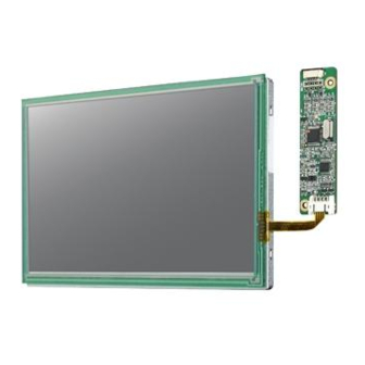
- Page 1 User Manual IDK-1110R-series TFT-LCD 10.4” SVGA (LED Backlight)
- Page 2 No part of this manual may be reproduced, copied, translated or transmitted in any form or by any means without the prior written permission of Advantech Co., Ltd. Information provided in this manual is intended to be accurate and reliable. How- ever, Advantech Co., Ltd.
- Page 3 Whether your new Advantech equipment is destined for the labo- ratory or the factory floor, you can be assured that your product will provide the reliability and ease of operation for which the name Advantech has come to be known.
- Page 4 Because of Advantech’s high quality-control standards and rigorous testing, most of our customers never need to use our repair service. If an Advantech product is defec- tive, it will be repaired or replaced at no charge during the warranty period. For out- of-warranty repairs, you will be billed according to the cost of replacement materials, service time and freight.
-
Page 5: Table Of Contents
Contents Chapter Overview..........1 General Description .................. 2 Display Characteristics................2 Mechanical Specification................2 Mechanical Dimension ................3 1.4.1 Front (For IDK-1110R-40SVA1E) ..........3 1.4.2 Rear (For IDK-1110R-40SVA1E)..........4 1.4.3 Front (For IDK-1110R-23SVA1E) ..........5 1.4.4 Rear (For IDK-1110R-23SVA1E)..........6 Absolute Maximum Ratings ..............7 1.5.1 Absolute Ratings of TFT LCD Module .......... - Page 6 Chapter Touch Screen ........25 Touch Characteristics ................26 Optical Characteristics ................26 Environment Characteristics ..............26 Mechanical Characteristics ..............26 Electronic Characteristics ............... 26 Chapter Touch Controller ....... 27 Touch Controller Characteristics............. 28 Specifications..................28 Environmental Feature................28 Pin Assignment and Description ............. 29 6.4.1 Connector and LED Location............
-
Page 7: Chapter 1 Overview
Chapter Overview... -
Page 8: General Description
General Description This specification applies to the 10.4 inch color TFT LCD module IDK-1110R-series. IDK-1110R-series designed with wide viewing angle; wide operating temperature and long life LEDs backlight is well suited to be the display units for Industrial Applica- tions. -
Page 9: Mechanical Dimension
Mechanical Dimension 1.4.1 Front (For IDK-1110R-40SVA1E) IDK-1110R User Manual... -
Page 10: Rear (For Idk-1110R-40Sva1E)
1.4.2 Rear (For IDK-1110R-40SVA1E) IDK-1110R User Manual... -
Page 11: Front (For Idk-1110R-23Sva1E)
1.4.3 Front (For IDK-1110R-23SVA1E) IDK-1110R User Manual... -
Page 12: Rear (For Idk-1110R-23Sva1E)
1.4.4 Rear (For IDK-1110R-23SVA1E) IDK-1110R User Manual... -
Page 13: Absolute Maximum Ratings
Absolute Maximum Ratings 1.5.1 Absolute Ratings of TFT LCD Module Value Item Symbol Unit Conditions Min. Max. Logic/LCD Drive -0.3 +4.0 [Volt] For IDK-1110R-40SVA1E Voltage Value Item Symbol Unit Conditions Min. Max. Logic/LCD Drive -0.3 +3.6 [Volt] For IDK-1110R-23SVA1E Voltage 1.5.2 Absolute Ratings of Environment Value... - Page 14 IDK-1110R User Manual...
-
Page 15: Chapter 2 Electrical Characteristics
Chapter Electrical Characteristics... -
Page 16: Tft Lcd Module
TFT LCD Module 2.1.1 Power specification (For IDK-1110R-40SVA1E) Value Parameter Symbol Unit Remark Min. Typ. Max. Logic/LCD Drive [Volt] VDD Current [mA] All Black Pattern (VDD=3.3V, at 60Hz) LCD Inrush Current Irush Note 1, Black Pattern, Rising time=470us VDD Power 0.924 - [Watt] All Black Pattern... -
Page 17: Signal Electrical Characteristics
2.1.3 Signal Electrical Characteristics Input signals shall be low or Hi-Z state when VDD is off. Value Parameter Symbol Unit Remark Min. Typ. Max. Differential Input [mV] VICM=1.2V High Threshold Differential Input [mV] VICM=1.2V Low Threshold Input Differential [mV] Voltage Differential Input VICM 1.45... -
Page 18: Backlight Unit
Backlight Unit 2.2.1 Parameter guideline for LED backlight (For IDK-1110R- 40SVA1E) Following characteristics are measured under a stable condition using an inverter at 25°C (Room Temperature): Value Parameter Symbol Unit Remark Min. Typ. Max. Input Voltage 10.8 12.6 [Volt] Input Current 0.32 100% PWM Duty Power Consumption... - Page 19 LED Forward Voltage 29.2 [Volt] = 25mA, Ta = 25°C -30°C LED Power Con- 1.92 [Watt] I = 25mA, sumption Ta = 25°C (total power) Operation Lifetime 25,00 30,00 Ta= 60 C RH<60% =25mA Tj <70°C Note1 Ta means ambient temperature of TFT-LCD module. Note2 VCC, Ivcc, PVCC, are defined for LED B/L.(100% duty of PWM dimming) Note3...
- Page 20 IDK-1110R User Manual...
-
Page 21: Chapter 3 Signal Characteristics
Chapter Signal Characteristics... -
Page 22: Pixel Format Image
Pixel Format Image Following figure shows the relationship between input signal and LCD pixel format. Pin Description LVDS is a differential signal technology for LCD interface and high speed data trans- fer device. The connector pin definition is as below. Note “Low”... -
Page 23: The Input Data Format
Table 3.1: Pin Description SEL68 6/ 8bits LVDS data input selection [H: 8bits L/NC: 6bit] The Input Data Format 3.3.1 SEL68 SEL68 = ”Low” or “NC” for 6 bits LVDS Input RxCLKIN RxIN0 RxIN1 RxIN1 SEL68 = “High” for 8 bits LVDS Input RxCLKIN RxIN0 RxIN1... -
Page 24: Interface Timing
Blue Data 7 Blue Data 6 Blue-pixel Data Blue Data 5 For 8 bits LVDS input, Blue Data 4 MSB: B7; LSB:B0 Blue Data 3 Blue Data 2 For 6 bits LVDS input, MSB: B5; LSB:B0 Blue Data 1 Blue Data 0 RxCLKIN LVDS Data Clock Data Enable Signal... -
Page 25: Input Timing Diagram
3.4.2 Input Timing Diagram Power ON/OFF Sequence VDD power and lamp on/off sequence is as follows. Interface signals are also shown in the chart. Signals from any system shall be Hi-Z state or low level when VDD is off. Power Sequence Timing(For IDK-1110R-40SVA1E) Parameter Value Unit... - Page 26 [ms] [ms] [ms] [ms] [ms] [ms] [ms] [ms] [ms] 1000 [ms] Power Sequence Timing(For IDK-1110R-23SVA1E) Parameter Value Unit Min. Typ. Max. [ms] [ms] [ms] [ms] [ms] [ms] [ms] [ms] [ms] [ms] [ms] [ms] 1000 [ms] The above on/off sequence should be applied to avoid abnormal function in the dis- play.
-
Page 27: Chapter 4 Display Connector Definition
Chapter Display Connector Definition... -
Page 28: Tft Lcd Signal(Cn1): Lvds Connector
TFT LCD Signal(CN1): LVDS Connector Table 4.1: Connector Connector Name / Description Signal Connector Manufacture STM, Hirose or compatible Connector Model Number STM-MSB24013P20HA or Compatitible Adapable Plug STM-P24013P20 or compatible Table 4.2: Pin Assignment Pin No. Signal Name Pin No. Signal Name RxIN0- RxIN0+... -
Page 29: Connector Specification((For Idk-1110R-23Sva1E)
Pin No. Symbol Description Color Pin1 LED anode Pin2 LED cathode White Pin3 LED cathode Black 4.3.2 Connector Specification((For IDK-1110R-23SVA1E) Connector Name / Description Signal Connector Manufacture ENTERY or compatible Connector Model Number Entery H203K-D05N-02Bor compatible Mating Model Number(CN3) Entery 3800K-F05N-03Ror compatible Pin No. - Page 30 IDK-1110R User Manual...
-
Page 31: Touch Screen
Chapter Touch Screen... -
Page 32: Touch Characteristics
Touch Characteristics TOUCH PANEL is resistance type that customer uses with flat display like LCD. Once operator touches it by resin PEN with round end or FINGER, the circuit for TOUCH PANEL sends coordinate point to PC from voltage at contact point. Optical Characteristics Item Specification... -
Page 33: Touch Controller
Chapter Touch Controller... -
Page 34: Touch Controller Characteristics
Touch Controller Characteristics Advantech ETM-RES05C Touch Control Board, the ultimate combo board. This touch panel controller provides the optimistic performance of your analog resistive touch panels for 4 wire models. It communicates with PC system directly through USB and RS-232 connector. You can see how superior the design is in sensitivity accuracy and friendly operation. -
Page 35: Pin Assignment And Description
Relative Humidity 95% at 60°C, RH Non-condensing Acquired RoHS certificate Requlatory FCC-B, CE approvals Dimension: 75 mm x 20 mm x 10 mm Pin Assignment and Description 6.4.1 Connector and LED Location JP1 Connector (USB&RS-232 Combo Interface) JP2 Connector (4-wire Touch screen interface) 6.4.2 Combo... -
Page 36: Combo Interface Connector, Jp1, Pins And Signal Descriptions 29 Figure 6.1 Board Mounted Header
Figure 6.1 Board mounted header 6.4.3 Touch Screen Connector, JP2, Pins and Signal Descriptions The Touch Screen connector, JP2, is a FFC/FPC SMD 1.0mm 4-pins 90 degree, Female type connector. The pins are numbered as shown in the table below. TS4 Pin # Signal Name Signal Description... -
Page 37: Characteristics
Appendix Optical Characteristics... -
Page 38: Optical Characteristics (For Idk-1110R-40Sva1E)
Optical Characteristics (for IDK-1110R- 40SVA1E) The optical characteristics are measured under stable conditions at 25°C (Room Temperature): Item Conditions Min. Typ. Max. Unit Note White IF= 50mA [cd/m2] Luminance (center point) Uniformity 9 Points 1, 2, 3 Contrast Ratio Response Time Rising [msec] Falling... - Page 39 Color / Chromaticity Red x 0.559 0.609 0.659 Coordinates Red y 0.283 0.333 0.383 (CIE 1931) Green x 0.315 0.365 0.415 Green y 0.520 0.570 0.620 Blue x 0.101 0.151 0.201 Blue y 0.056 0.106 0.156 White x 0.28 0.31 0.34 White y 0.30...
- Page 40 IDK-1110R User Manual...
-
Page 41: Handling Precautions
Appendix Handling Precautions... -
Page 42: Handling Precautions
Handling Precautions The optical characteristics are measured under stable conditions at 25°C (Room Temperature) Since front polarizer is easily damaged, pay attention not to scratch it. Be sure to turn off power supply when inserting or disconnecting from input con- nector. - Page 43 No part of this publication may be reproduced in any form or by any means, electronic, photocopying, recording or otherwise, without prior written permis- sion of the publisher. All brand and product names are trademarks or registered trademarks of their respective companies. © Advantech Co., Ltd. 2012...
Need help?
Do you have a question about the IDK-1110R-series and is the answer not in the manual?
Questions and answers