Table of Contents
Advertisement
Quick Links
Advertisement
Table of Contents

Related Manuals for Advantech IDK-1110P Series


Summary of Contents for Advantech IDK-1110P Series
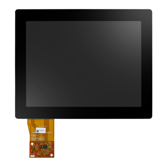
- Page 1 User Manual IDK-1110P-series TFT-LCD 10.4” XGA (LED Backlight)
- Page 2 No part of this manual may be reproduced, copied, translated or transmitted in any form or by any means without the prior written permission of Advantech Co., Ltd. Information provided in this manual is intended to be accurate and reliable. How- ever, Advantech Co., Ltd.
- Page 3 Whether your new Advantech equipment is destined for the labo- ratory or the factory floor, you can be assured that your product will provide the reliability and ease of operation for which the name Advantech has come to be known.
- Page 4 Because of Advantech’s high quality-control standards and rigorous testing, most of our customers never need to use our repair service. If an Advantech product is defec- tive, it will be repaired or replaced at no charge during the warranty period. For out- of-warranty repairs, you will be billed according to the cost of replacement materials, service time and freight.
-
Page 5: Table Of Contents
Contents Chapter Overview..........1 General Description .................. 2 Display Characteristics................2 Mechanical Specification................2 Mechanical Dimension ................3 Absolute Maximum Ratings ..............3 1.5.1 Absolute Ratings of the TFT LCD Module ........3 1.5.2 Absolute Environment Ratings............3 Block Diagram................... 4 Figure 1.1 TFT LCD module ............ - Page 6 Specifications..................24 Environmental Feature................24 Mechanical Drawing................25 6.4.1 Mechanical size ................25 Pin Assignment and Description ............. 26 6.5.1 Touch Line Pin Definition............26 6.5.2 Interface Detection and Pin Definition ........26 Table 6.1: JL3 / 4PIN / USB ............27 Table 6.2: JL4 / 7 PIN / I2C/ UART ...........
-
Page 7: Chapter 1 Overview
Chapter Overview... -
Page 8: General Description
General Description This specification applies to the 10.4 inch color TFT LCD module IDK-1110P-series. IDK-1110P is designed with wide viewing angle; wide operating temperature and long life LED backlight which is well suited for Industrial Applications. LED driving board for backlight unit is included in this panel and the structure of the LED units is replaceable. -
Page 9: Mechanical Dimension
Mechanical Dimension AA Center 2-USER HOLE M2X2.5 Patone Black C 2-USER HOLE M2X2.5 Unit:mm Absolute Maximum Ratings 1.5.1 Absolute Ratings of the TFT LCD Module Value Item Symbol Unit Min. Max. Logic/LCD Drive -0.3 [Volt] Voltage 1.5.2 Absolute Environment Ratings Value Item Symbol... -
Page 10: Block Diagram
Block Diagram Figure 1.1 TFT LCD module IDK-1110P User Manual... -
Page 11: Chapter 2 Electrical Characteristics
Chapter Electrical Characteristics... -
Page 12: Tft Lcd Module
TFT LCD Module 2.1.1 Electrical Characteristics Ta=25 ± 2 ° Parameter Symbol Value Unit Note Min. Typ. Max. Power Supply Voltage Rush Current RUSH White Power Supply Current Black Power Consumption LVDS differential input voltage lVIDl 100.0 600.0 LVDS common input voltage VICM Note! The assembly should be always operated within above ranges. -
Page 13: Backlight Unit
Note! The specified power supply current is under the conditions at Vcc=3.3 V, Ta=25+/- 2 C, fv=60 Hz, whereas a power dissipation check pattern is ° displayed. Backlight Unit 2.2.1 Parameter guideline for LED backlight Following characteristics are measured under a stable conditions using an inverter at 25°... - Page 14 Symbol Description Remark Converter input voltage 12 V Converter input voltage 12 V Converter input voltage 12 V Converter input voltage 12 V Converter ground Ground Converter ground Ground Converter ground Ground Converter ground Ground Enable pin 3.3 V Backlight Adjust PWM Dimming IDK-1110P User Manual...
-
Page 15: Chapter 3 Signal Characteristics
Chapter Signal Characteristics... -
Page 16: Pixel Format Image
Pixel Format Image Following figure shows the relationship between input signal and LCD pixel format. 1023 1024 768th Pin Description LVDS is a differential signal technology for LCD interface and high speed data trans- fer device. The connector pin definition is as below. Table 3.1: Pin Description Pin No. -
Page 17: Input Data Format
Table 3.1: Pin Description RX1+ Positive transmission data of pixel 1 Ground RX2- Negative transmission data of pixel 2 RX2+ Positive transmission data of pixel 2 Ground RXCLK- Negative of clock RXCLK+ Positive of clock Ground RX3- Negative transmission data of pixel 3 RX3+ Positive transmission data of pixel 3 Ground... - Page 18 Note! Please follow PSWG. Note! R/G/B data 7: MSB, R/G/B data 0: LSB. Table 3.2: Input Data Format Signal Name Description Remark Red Data 7 Red Data 6 Red-pixel Data Red Data 5 For 8 bits LVDS input, Red Data 4 MSB: R7;...
-
Page 19: Interface Timing
Interface Timing 3.4.1 Timing Characteristics DE mode only (For IDK-1110P-40SVA1E) Table 3.3: Timing Characteristics (For IDK-1110P-40SVA1E) Parameter Symbol Min. Typ. Max. Unit Condition Clock frequency Period Vertical Active Section Blanking Period 1104 1344 1800 Horizontal Active 1024 Clock Section Blanking Note! Frame rate is 60 Hz. -
Page 20: Power On/Off Sequence
Power ON/OFF Sequence To prevent a latch-up or DC operation of LCD assembly, the power on/off sequence should be as the diagram below. Power Sequence Timing Parameter Value Unit Min. Typ. Max. [ms] [ms] [ms] [ms] [ms] [ms] [ms] [ms] [ms] IDK-1110P User Manual... -
Page 21: Chapter 4 Display Connector Definition
Chapter Display Connector Definition... -
Page 22: Tft Lcd Signal(Cn1): Lvds Connector
TFT LCD Signal(CN1): LVDS Connector Table 4.1: Connector Connector Name / Description Signal Connector Manufacturer JAE or compatible Connector Model Number FI-XB30SRL-HF11 or compatible Adaptable Plug FI-X30C2L or compatible Table 4.2: Pin Assignments Pin No. Signal Name Pin No. Signal Name RPFI SEL6/8 RX0-... -
Page 23: Led Backlight Unit (Cn2): Led Driver Connector
LED Backlight Unit (CN2): LED Driver Connector Connector Name / Designation LED Light Bar Connector / Backlight lamp Manufacturer ACES or compatible Connector Model Number 91208-01001 or compatible Mating Model Number 91209-01011 or compatible Table 4.3: LED Backlight Pin Symbol Description Remark Converter input voltage... - Page 24 IDK-1110P User Manual...
-
Page 25: Chapter 5 Touch Screen
Chapter Touch Screen... -
Page 26: Touch Characteristics
Touch Characteristics This touch panel is a Projected Capacitive type used with flat displays like LCDs. Once an operator touches it, this is measurable as a change in capacitance and the change sensed as a 'touch' by the controller. Optical Characteristics Item Specification Remarks... -
Page 27: Mechanical Characteristics
Mechanical Characteristics Positional Accuracy: Perimeter of Active Area: it is in the 10mm area inside from active area, the accuracy specifications are based on touch panel controllers and drivers to define, the percent- age of positional inaccuracy is less than 2.5% as defined below. Inner Active Area: it is the area of 10mm inside of the active area, the accuracy specifications are based on PenMount touch panel controllers and drivers to define, the percentage of posi- tional inaccuracy is less than 1.5% as defined below. - Page 28 IDK-1110P User Manual...
-
Page 29: Chapter 6 Touch Controller
Chapter Touch Controller... -
Page 30: Touch Controller Characteristics
Touch Controller Characteristics The PenMount PM1310 control board is a high specification (Projected Capacitive Input, PCI) touch panel controller product introduced by PenMount. The PenMount PM1310 can be applied in the consumer, commercial and the industrial fields. The PenMount PM1310 provides two types of interface, USB, I2C and UART inter- face, and also supports a wide range of operating systems such as Windows and Linux.There are four connectors on this board: two 40 Pins ZIF connectors for PCI touch screen FPC cable, one USB connector for 4-pin USB cable, and one I2C/... -
Page 31: Mechanical Drawing
Mechanical Drawing 6.4.1 Mechanical size IDK-1110P User Manual... -
Page 32: Pin Assignment And Description
Pin Assignment and Description 6.5.1 Touch Line Pin Definition 6.5.2 Interface Detection and Pin Definition IDK-1110P User Manual... -
Page 33: Connector Specification
Table 6.1: JL3 / 4PIN / USB PIN No. Signal Function Vcc (USB 5 V) Ground Table 6.2: JL4 / 7 PIN / I C/ UART PIN No. Signal Function UART Remark Ground SCL,RXD SDA,TXD Pull low at least 2 μs to reset the P2-08 Reset Float Float... -
Page 34: Driver Utilities
Driver Utilities 6.7.1 Drivers For I Windows CE: Provide binary driver for freescale iMX platform. Other platform by request. Linux / Android: Provid source code for integration. For USB / UART Windows 2000, XP, 2003: Single touch, mouse driver. ... -
Page 35: Optical Characteristics
Appendix Optical Characteristics... -
Page 36: Optical Characteristics
Optical Characteristics The optical characteristics are measured under stable conditions at 25°C (Room Temperature): Item Conditions Min. Typ. Max. Unit Note White IF= 50mA [cd/m2] Luminance (center point) Uniformity 5 Points 1, 2, 3 Contrast Ratio 1000 Rising [msec] Response Time Falling [msec] Raising + Falling... - Page 37 Note! Definition of Contrast Ratio Contrast ratio is calculated with the following formula : Contrast Ratio (CR)=(White) Luminance of ON (Black) Luminance of Note! Definition of Luminance: Measure the luminance of white state at center point. Note! Definition of Luminance Uniformity: Measured Maximum luminance...
- Page 38 IDK-1110P User Manual...
-
Page 39: Handling Precautions
Appendix Handling Precautions... -
Page 40: Handling Precautions
Handling Precautions The optical characteristics are measured under stable conditions at 25°C (Room Temperature) Since front polarizer is easily damaged, take extra care not to scratch it. Be sure to turn off power supply when inserting or disconnecting from input con- nector. - Page 41 No part of this publication may be reproduced in any form or by any means, electronic, photocopying, recording or otherwise, without prior written permis- sion of the publisher. All brand and product names are trademarks or registered trademarks of their respective companies. © Advantech Co., Ltd. 2015...
Need help?
Do you have a question about the IDK-1110P Series and is the answer not in the manual?
Questions and answers