
Subscribe to Our Youtube Channel
Related Manuals for Advantech IDK-1110P-50XGB1


Summary of Contents for Advantech IDK-1110P-50XGB1
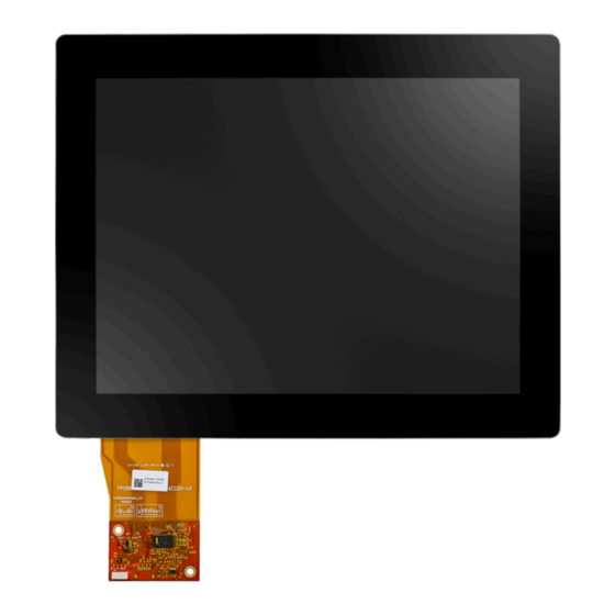
- Page 1 User Manual IDK-1110P-50XGB1 10.4” XGA Industrial Display Kit with Projected Capacitive Touch Solution...
- Page 2 No part of this manual may be reproduced, copied, translated, or transmitted in any form or by any means without the prior written permission of Advantech Co., Ltd. The information provided in this manual is intended to be accurate and reliable.
- Page 3 Product Warranty (2 years) Advantech warrants the original purchaser that each of its products will be free from defects in materials and workmanship for two years from the date of purchase. This warranty does not apply to any products that have been repaired or altered by persons other than repair personnel authorized by Advantech, or products that have been subject to misuse, abuse, accident, or improper installation.
- Page 4 Whether your new Advantech equipment is destined for the labo- ratory or the factory floor, you can be assured that your product will provide the reliability and ease of operation for which the name Advantech has come to be known.
-
Page 5: Table Of Contents
Specifications................24 3.2.2 Pin Assignment and Description ..........25 Typical Optical Characteristics..............25 Appendix A LCD Optical Characteristics .....27 Test Conditions ..................28 Optical Specifications................28 Appendix B Safety Precautions ......31 Assembly and Handling Precautions ............32 IDK-1110P-50XGB1 User Manual... - Page 6 Storage Precautions ................32 Other Precautions ................... 33 IDK-1110P-50XGB1 User Manual...
-
Page 7: Chapter 1 Overview
Chapter Overview... -
Page 8: General Description
General Description The Advantech IDK-1110P-50XGB1 comes with a 10.4" industrial grade LCD display with projected capacitive (PCAP) touch with low power consumption. This display is ideal for embedded applications that necessitate maximum flexibility for mechanical design. Specifications 1.2.1 LCD Panel Display Size: 10.4", 4:3... - Page 9 Relative Humidity (%RH) of LCD only IDK-1110P-50XGB1 User Manual...
-
Page 10: Mechanical Characteristics
Mechanical Characteristics Front View Unit: mm Rear View Note: Tolerances unless marked are ± 0.5 mm IDK-1110P-50XGB1 User Manual... -
Page 11: Chapter 2 Lcd Display
Chapter LCD Display... -
Page 12: Functional Block Diagram
-0.3 [Volt] Note (1) Permanent damage to the device may occur if maximum values are exceeded. Operation should be restricted to the conditions described under Normal Operating Conditions. Note (2) Specified values are for LED light bar. IDK-1110P-50XGB1 User Manual... -
Page 13: Lcd Electronics Specification
Power Consumption 1.67 LVDS Differential Input Voltage LVDS Common Input Voltage Logic High Input Voltage Logic Low Input Voltage LVDS terminating resistor Note (1) The assembly should always be operated within above ranges. Note (2) Measurement conditions: IDK-1110P-50XGB1 User Manual... - Page 14 Note (3) The specified power supply current is under the conditions at Vcc = 3.3V, Ta = 25 ± 2 °C (77 ± 3.6 °F), fv = 60 Hz, whereas a power dissipa- tion check pattern below is displayed. IDK-1110P-50XGB1 User Manual...
-
Page 15: Backlight Unit
(2), Sugges- tion, @190Hz<fP WM<1kHz PWM Control Duty Ratio (2), @ 1kHz?fPWM <20kHz PWM Control Frequency fPWM LED Life Time 50,000 - Note (1) LED current is measured by utilizing a high frequency current meter shown below: IDK-1110P-50XGB1 User Manual... - Page 16 Ta = 25 ± 2 º C (77 ± 3.6 °F) - and Duty 100% until the brightness becomes ≤ 50% of its original value. Operating LED at high temperature condition will reduce life time and lead to color shift. IDK-1110P-50XGB1 User Manual...
-
Page 17: Input Terminal Pin Assignment
Negative transmission data of pixel 3 RX3+ Positive transmission data of pixel 3 Ground No Connection ( 4 ) Note (1) Connector Part No.: P-TWO 187106-30091 or STM, MSCK2407P30.D or equivalent. Note (2) User's connector Part No.: JAE FI-X30H(L) or equivalent. IDK-1110P-50XGB1 User Manual... - Page 18 Converter Ground Ground VGND Converter Ground Ground VGND Converter Ground Ground Enable Pin 3.3 V, Note (3) PWM Dimming Backlight Adjustment (190-210Hz, Hi: 3.3VDC, Lo: 0VDC) , Note (3) Note (1) Connector Part No.: ACES,91208-01001-H01 or equivalent IDK-1110P-50XGB1 User Manual...
- Page 19 Note (2) User's connector Part No.: ACES,91209-01011 or equivalent Note (3) EN(BLON), ADJ(E_PWM) as shown below: IDK-1110P-50XGB1 User Manual...
-
Page 20: Color Data Input Assignment
Red(62) Red(63) Green(0) / Dark Green(1) Green(2) Gray Scale Green Green (61) Green (62) Green (63) Blue(0) / Dark Blue(1) Blue(2) Gray Scale Blue Blue(61) Blue(62) Blue(63) Note (1) 0: Low Level Voltage, 1: High Level Voltage IDK-1110P-50XGB1 User Manual... - Page 21 / Dark Green(1) Green(2) Gray Scale Green Green (253) Green (254) Green (255) Blue(0) / Dark Blue(1) Blue(2) Gray Scale Blue Blue(253) 0 Blue(254) 0 Blue(255) 0 Note (1) 0: Low Level Voltage, 1: High Level Voltage IDK-1110P-50XGB1 User Manual...
-
Page 22: Interface Timing
Note (1) Because this module is operated by DE only mode, Hsync and Vsync input signals should be set to low logic level or ground. Otherwise, this module will operate abnormally. Note (2) The Tv(Tvd+Tvb) must be integer, otherwise, the module will operate abnormally. IDK-1110P-50XGB1 User Manual... - Page 23 Input Signal Timing Diagram LVDS Timing Diagram IDK-1110P-50XGB1 User Manual...
- Page 24 Note (b) The Tv(Tvd+Tvb) must be integer, otherwise, the module will operate abnormally. Note (c) The Tv(Tvd+Tvb) must be integer, otherwise, the module will operate abnormally. IDK-1110P-50XGB1 User Manual...
-
Page 25: Power On/Off Sequence
(7)There might be slight electronic noise when LCD is turned off (even backlight unit is also off). To avoid this symptom, we suggest "Vcc falling timing" to follow "T7 spec". Table 2.8: Timing Specifications: Value Parameter Units IDK-1110P-50XGB1 User Manual... -
Page 26: The Input Data Format
The Input Data Format Note (1) R/G/B data 7: MSB, R/G/B data 0: LSB Note (2) Please follow PSWG IDK-1110P-50XGB1 User Manual... -
Page 27: Scanning Direction
The following figures show the image seen from the front view. The arrow indicates the direction of the scan. Fig.1 Normal Scan Fig.2 Reverse Scan Fig. 1 Normal scan (pin 7, RPFI = Low or NC) Fig. 2 Reverse scan (pin 7, RPFI = High) IDK-1110P-50XGB1 User Manual... - Page 28 IDK-1110P-50XGB1 User Manual...
-
Page 29: Chapter 3 Touchscreen And Touch Controller
Chapter Touchscreen and Touch Controller... -
Page 30: Mechanical Dimensions And Construction
1pt +/- 1mm offset / 10mm – Touch (point) accuracy: 1pt +/- 1mm Interface: USB 2.0 Firmware resolution: 16384x16384 Response time: Average < 25ms Report Rate(points/sec): >100 Hz (Typical) Power consumption: Active mode < 90mA @ 5Vdc IDK-1110P-50XGB1 User Manual... -
Page 31: Pin Assignment And Description
Static electricity comes from the touch side of the touch panel Note! Testing result are highly relevant to mounting methods. 3.2.2 Pin Assignment and Description Typical Optical Characteristics Visible Light Transmission: 90±3% Haze: < 3% IDK-1110P-50XGB1 User Manual... - Page 32 IDK-1110P-50XGB1 User Manual...
-
Page 33: Appendix Alcd Optical Characteristics
Appendix LCD Optical Characteristics... -
Page 34: Test Conditions
ɵX- Viewing Angle ɵY+ Vertical ɵY- Definition: Grayscale Maximum: Grayscale 255 (10 bits: grayscale 1023; 8 bits: grayscale 255; 6 bits: grayscale 63) White: Luminance of grayscale Maximum (All R,G,B) Black: Luminance of grayscale 0 (All R,G,B) IDK-1110P-50XGB1 User Manual... - Page 35 The contrast ratio can be calculated by the following expression at cen- ter point. Contrast Ratio (CR) = White / Black Note Note (3) Definition of Response Time (T Note (4) Definition of Luminance of White (L Measure the luminance of White at center point. IDK-1110P-50XGB1 User Manual...
- Page 36 40 minutes in a windless room. The measurement placement of module should be in accordance with module drawing. Note (6) Definition of White Variation ( Measure the luminance of White at 5 points. Luminance of White: L(X), where X is from 1 to 5. IDK-1110P-50XGB1 User Manual...
-
Page 37: Appendix B Safety Precautions
Appendix Safety Precautions... -
Page 38: Assembly And Handling Precautions
PRODUCT SPECIFICATION Version 2.0 20 July 2021 32 / 42 The copyright belongs to InnoLux. Any unauthorized use is prohib- ited. IDK-1110P-50XGB1 User Manual... - Page 39 Static information display recommended to use with moving image. Cycling display between 5 minutes of information for static displays and 10 sec- onds for moving images Abnormal condition means conditions not defined in normal conditions IDK-1110P-50XGB1 User Manual...
- Page 40 IDK-1110P-50XGB1 User Manual...
- Page 41 No part of this publication may be reproduced in any form or by any means, such as electronically, by photocopying, recording, or otherwise, without prior written permission from the publisher. All brand and product names are trademarks or registered trademarks of their respective companies. © Advantech Co., Ltd. 2022...
Need help?
Do you have a question about the IDK-1110P-50XGB1 and is the answer not in the manual?
Questions and answers