Edwards STP Series Instruction Manual
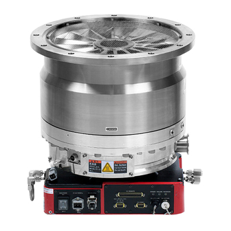
Turbomolecular pumps
Hide thumbs
Also See for STP Series:
- Instruction manual (167 pages) ,
- Instruction manual (23 pages) ,
- Instruction manual (37 pages)
Table of Contents
Advertisement
Instruction Manual
STP Series Turbomolecular Pumps
I/O Remote Interface
Applicable Models
Read through the Safety Precautions and
each section of this Manual carefully before
using the STP pump.
Keep this Manual in a place where you can
quickly access it at any time.
Read this Manual thoroughly and keep it with
the Turbomolecular Pump Instruction Manual.
◼ STP-iXA3307 series
◼ STP-iXA3307 -HV series
◼ STP-iXA4507 series
◼ STP-iXA4507 -HV series
Copyright 2023 Edwards Japan Limited. All rights reserved. Printed in Japan.
MT-91E-C01-0
2023.10
Advertisement
Table of Contents

Related Manuals for Edwards STP Series


Summary of Contents for Edwards STP Series
- Page 1 Keep this Manual in a place where you can quickly access it at any time. Read this Manual thoroughly and keep it with the Turbomolecular Pump Instruction Manual. 2023.10 Copyright 2023 Edwards Japan Limited. All rights reserved. Printed in Japan.
- Page 2 This page is intentionally blank.
-
Page 3: Table Of Contents
I/O Remote Interface CONTENTS PAGE Section Title Page INTRODUCTION Scope and definitions General description INSTALLATION Unpacking Precautions before installation User connections and indicator for I/O Remote 2.3.1 X4 REMOTE socket 2.3.2 X2 COM2 socket 2.3.3 X3 VALVE socket 2.3.4 "STATUS" LED 2.3.5 X5 STP-LINK socket 2.3.6... - Page 4 I/O Remote Interface ILLUSTRATIONS PAGE PAGE Figure Title Page I/O Remote Interface which integrated to the pump User interface of I/O Remote Interface X4 REMOTE connector Cable connection to the I/O Remote interface Example of cable installation in metallic duct Pump operation method X4 REMOTE input signal pins (contact input) X4 REMOTE input signal pins (contact output)
-
Page 5: Introduction
This manual provides installation, operation and maintenance instructions for the I/O Remote Interface. You must use the I/O Remote Interface as specified in this manual otherwise the protection provided by the equipment may be impaired. Edwards takes no responsibility for damage or injury caused by improper use of the equipment. -
Page 6: General Description
I/O Remote Interface General description The remote input/output signal connector, "X4 REMOTE", is used for input/output remote signals for I/O Remote Interface. The connectors for the I/O Remote Interface are on the front panel of the STP pump. Refer to Figure 1. Front panel (a) Front panel of STP Pump with I/O Remote Interface I/O Remote Interface connector... -
Page 7: Installation
Check outer package for damage and that the delivery note corresponds to the purchase order. Note : The I/O Remote Interface is implemented into the STP Pump by Edwards Note : It is recommended to keep the packaging materials, such as the corrugated fibreboard container and cushioning material for possible re-use. -
Page 8: X4 Remote Socket
I/O Remote Interface 2.3.1 X4 REMOTE socket X4 REMOTE connector is of D-Sub type (37 pins, socket type). The screws for the connector are M2.6. Note : The connector (pin type) is not included with the STP pump. Prepare it at your company. Note : It is recommended to use a shielded cable and connect both sides of the shells to the ground. -
Page 9: Status" Led
I/O Remote Interface 2.3.4 "STATUS" LED The STP pump operation status is indicated by the colors and flashing patterns of the "STATUS" LED. Refer to the STP pump instruction manual for detailed specifications. 2.3.5 X5 STP-LINK socket Connects the communication cable for the STP-Link (optional accessory) or the Display unit iDT-002 (optional accessory). - Page 10 I/O Remote Interface CAUTION Connect each cable securely with caution, avoiding any obstacles. DO NOT place heavy objects on the cables or bend them excessively. Support each cable so as not to apply direct force to the connectors or terminals. If any problem occurs in cables, connectors or terminals, the STP pump may not function normally.
-
Page 11: Operation
I/O Remote Interface OPERATION WARNING The I/O Remote Interface provides remote control of an Edward’s pump. You should refer to the safety information in the pump instruction manual. This unit should not be relied upon for safety related functions. Input operation port setting The STP pump needs to set the hardware which operates the STP pump before the operation. -
Page 12: Starting/Stopping The Stp Pump
I/O Remote Interface Starting/stopping the STP pump This section shows methods to operate starting/stopping the STP pump with the parallel part. Starting the pump Stopping the pump Short the circuit between (1)-(3). Open the circuit between (1)-(3). Table 1 - Starting/stopping the STP pump (X4 REMOTE) X4 REMOTE connector CLOSE... -
Page 13: Parallel Port Input/Output Signal
I/O Remote Interface Parallel port input/output signal 3.5.1 Input signal pins When using contact input, refer to Table 3 and Figure 7. The input signal pins function only when the input operation port is set to the parallel port. Two abbreviations are used in Table 3 and Figure 7: •... -
Page 14: X4 Remote Input Signal Pins (Contact Input)
I/O Remote Interface Figure 7 - X4 REMOTE input signal pins (contact input) Note : 1 pin (0 V) is isolated from the frame ground. Note : The input current of the remote input signal is approximately 3.5 mA. When the remote operation with a relay, make sure the minimum load of a relay contact is lower than that. -
Page 15: Output Signal Pins
I/O Remote Interface 3.5.2 Output signal pins Use the output signal pins according to Table 6, Table 7, and Figure 8. The pins can function when the input operation port is either in the parallel port setting or the serial port setting. Three abbreviations are used in Table 6 and Table 7, and Figure 8. -
Page 16: X4 Remote Output Signal Pins (Continued)
I/O Remote Interface Description (24) The pins for outputting multiple functions signal PROG OUT One of the following functions is available by changing the N.O. OUT setting via the serial port. (refer to Section 5, "SERIAL PROG OUT OUT COM COMMUNICATION PROTOCOL"... -
Page 17: X4 Remote Input Signal Pins (Contact Output)
I/O Remote Interface ACCELERATION state signal output pins NORMAL OPERATION state signal output pins BRAKE OPERATION state signal output pins IO ENABLE stat signal output pins FAILURE state signal output pins MULTIFUNCTION signal output pins Figure 8 - X4 REMOTE input signal pins (contact output) MT-91E-C01-0 Page 13... -
Page 18: X4 Remote Output Signal Pin That The States Change According To Abnormality Notification/Warning Notification
I/O Remote Interface Table 8 shows the rated specification of the seven photo relays' contacts. Resistance Load (COS Ø=1) Maximum voltage 30 V DC Maximum rated current 0.1 A Table 8 - The rated specification of the seven photo relays' contacts Figure 9 - X4 REMOTE output signal pin that the states change according to abnormality notification/warning notification Figure 10 - X4 REMOTE output signal pin that the states change according to rotation speed... -
Page 19: Maintenance
I/O Remote Interface MAINTENANCE Inspect the electrical connections Carry out the following checks regularly when maintaining the pumping system. 1. Inspect the electrical cables and check that they are not damaged. Repair or replace any damaged cables. 2. Inspect the electrical connections and check that they are secure. Tighten any loose connections found. - Page 20 I/O Remote Interface This page is intentionally blank. MT-91E-C01-0 Page 16...
-
Page 21: Service, Spares And Accessories
• Item number and description of part Service Edwards products are supported by a world-wide network of Edwards Service office. Each Service office offers a wide range of options including: equipment decontamination; service exchange; repair; rebuild and testing to factory specifications. Equipment, which has been serviced, repaired or rebuilt, is returned with a full warranty. - Page 22 I/O Remote Interface This page is intentionally blank. MT-91E-C01-0 Page 18...
- Page 23 For more information, contact the nearest Service Office. http://www.edwardsvacuum.com/ Manufacturer: Edwards Japan Limited 1078-1, Yoshihashi, Yachiyo-shi, Chiba 276-8523 JAPAN Telephone: Domestic 047-458-8836 International +81-47-458-8836 Facsimile: Domestic 047-458-8835 International +81-47-458-8835 Copyright 2023 Edwards Japan Limited. All rights reserved.
Need help?
Do you have a question about the STP Series and is the answer not in the manual?
Questions and answers