
Subscribe to Our Youtube Channel
Related Manuals for Huawei UPS5000-E-180 kVA


Summary of Contents for Huawei UPS5000-E-180 kVA
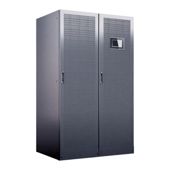
- Page 1 UPS5000-E-180 kVA User Manual (Integrated UPS, 30 kVA Power Modules) Issue Date 2024-01-30 HUAWEI DIGITAL POWER TECHNOLOGIES CO., LTD.
- Page 2 Notice The purchased products, services and features are stipulated by the contract made between Huawei Digital Power Technologies Co., Ltd. and the customer. All or part of the products, services and features described in this document may not be within the purchase scope or the usage scope. Unless otherwise specified in the contract, all statements, information, and recommendations in this document are provided "AS IS"...
-
Page 3: About This Document
Indicates a potentially hazardous situation which, if not avoided, could result in equipment damage, data loss, performance deterioration, or unanticipated results. NOTICE is used to address practices not related to personal injury. Issue 05 (2024-01-30) Copyright © Huawei Digital Power Technologies Co., Ltd. - Page 4 ● Added the dust cover check in the "Verifying the Installation" section. ● Added the description of installing EPO cables. ● Added the no-load loss and power distribution system items. ● Updated the "Maintenance" section. Issue 05 (2024-01-30) Copyright © Huawei Digital Power Technologies Co., Ltd.
- Page 5 About This Document Issue Date Description 2022-12-30 ● Updated the content about parts replacement. ● Updated the description about initial startup. 2021-10-18 This issue is the first official release. Issue 05 (2024-01-30) Copyright © Huawei Digital Power Technologies Co., Ltd.
-
Page 6: Table Of Contents
2.3.4.2 Dry Contact Card (MUE05A)............................36 2.3.4.3 Monitoring Interface Card (MUS05A)........................41 2.3.5 MDU....................................... 45 3 Technical Specifications....................... 48 4 Installation and Cable Connection..................55 4.1 Installation Preparations..............................55 4.1.1 Tools....................................... 55 Issue 05 (2024-01-30) Copyright © Huawei Digital Power Technologies Co., Ltd. - Page 7 6.3.1.1 Forced Equalized Charging Test..........................116 6.3.1.2 Shallow Discharge Test.............................. 117 6.3.1.3 Capacity Test................................. 118 6.3.2 Lithium Battery Test............................... 119 6.3.2.1 Shallow Discharge Test.............................. 119 6.3.2.2 Capacity Test................................. 120 Issue 05 (2024-01-30) Copyright © Huawei Digital Power Technologies Co., Ltd.
- Page 8 9.3 Transferring from Maintenance Bypass Mode to Normal Mode............... 136 9.4 EPO......................................136 9.5 Clearing the EPO State..............................137 9.6 Downloading Data................................138 A Power Distribution Silkscreen Description..............139 B Acronyms and Abbreviations................... 140 Issue 05 (2024-01-30) Copyright © Huawei Digital Power Technologies Co., Ltd.
-
Page 9: Safety Information
Equipment damage due to force majeure such as earthquakes, floods, volcanic eruptions, debris flows, lightning strikes, fires, wars, armed conflicts, typhoons, hurricanes, tornadoes, and extreme weather conditions ● Operation beyond the conditions specified in this document Issue 05 (2024-01-30) Copyright © Huawei Digital Power Technologies Co., Ltd. -
Page 10: Personal Safety
D ANGER During operations, use dedicated insulated tools to prevent electric shocks or short circuits. The insulation and voltage resistance must comply with local laws, regulations, standards, and specifications. Issue 05 (2024-01-30) Copyright © Huawei Digital Power Technologies Co., Ltd. - Page 11 – Trained personnel: personnel who are trained in technology and safety, have required experience, are aware of possible hazards on themselves in Issue 05 (2024-01-30) Copyright © Huawei Digital Power Technologies Co., Ltd.
-
Page 12: Equipment Safety
Issue 05 (2024-01-30) Copyright © Huawei Digital Power Technologies Co., Ltd. -
Page 13: Battery Safety
Do not expose batteries at high temperatures or around heat sources, such as scorching sunlight, fire sources, transformers, and heaters. Battery overheating may cause leakage, smoke, flammable gas release, thermal runaway, fire, or explosion. Issue 05 (2024-01-30) Copyright © Huawei Digital Power Technologies Co., Ltd. - Page 14 . To prevent fire or equipment corrosion, ensure that flammable gases are properly exhausted. D ANGER The gases generated by a burning battery may irritate your eyes, skin, and throat. Take protective measures. Issue 05 (2024-01-30) Copyright © Huawei Digital Power Technologies Co., Ltd.
- Page 15 WARNING After batteries are discharged, charge them in time to avoid damage due to overdischarge. Issue 05 (2024-01-30) Copyright © Huawei Digital Power Technologies Co., Ltd.
- Page 16 Battery use scenarios are changed without prior approval from the Company. – Battery maintenance is not performed according to the instructions in the user manual, for example, failing to check battery terminals regularly. Issue 05 (2024-01-30) Copyright © Huawei Digital Power Technologies Co., Ltd.
- Page 17 In the case of electrolyte leakage or structural deformation, contact the installer or Issue 05 (2024-01-30) Copyright © Huawei Digital Power Technologies Co., Ltd.
- Page 18 Inhalation: Evacuate from contaminated areas, get fresh air immediately, and seek immediate medical attention. ● Eye contact: Immediately wash your eyes with water for at least 15 minutes, do not rub your eyes, and seek immediate medical attention. Issue 05 (2024-01-30) Copyright © Huawei Digital Power Technologies Co., Ltd.
-
Page 19: Electrical Safety
Before connecting cables, ensure that the equipment is intact. Otherwise, electric shocks or fires may occur. D ANGER Non-standard and improper operations may result in fire or electric shocks. Issue 05 (2024-01-30) Copyright © Huawei Digital Power Technologies Co., Ltd. - Page 20 ● Before installing power cables, check that cable labels are correct and cable terminals are insulated. Issue 05 (2024-01-30) Copyright © Huawei Digital Power Technologies Co., Ltd.
- Page 21 ● Ensure that the protective ground point of the equipment is reliably connected to the ground screw of the metal enclosure (connection resistance: ≤ 0.1 ohms). Issue 05 (2024-01-30) Copyright © Huawei Digital Power Technologies Co., Ltd.
- Page 22 Do not perform any improper operations, for example, dropping cables directly from a vehicle. Otherwise, the cable performance may deteriorate due to cable damage, which affects the current-carrying capacity and temperature rise. Issue 05 (2024-01-30) Copyright © Huawei Digital Power Technologies Co., Ltd.
-
Page 23: Environmental Requirements
Do not expose the equipment to flammable or explosive gas or smoke. Do not perform any operation on the equipment in such environments. D ANGER Do not store any flammable or explosive materials in the equipment area. Issue 05 (2024-01-30) Copyright © Huawei Digital Power Technologies Co., Ltd. - Page 24 ● Ensure that the ground in the installation environment is solid, free from spongy or soft soil, and not prone to subsidence. The site must not be located Issue 05 (2024-01-30) Copyright © Huawei Digital Power Technologies Co., Ltd.
-
Page 25: Mechanical Safety
Do not use tools that have signs of scratches or fail to pass the inspection or whose inspection validity period has expired. Ensure that the tools are secure and not overloaded. Issue 05 (2024-01-30) Copyright © Huawei Digital Power Technologies Co., Ltd. - Page 26 If two persons or more move a heavy object together, ensure that the object is lifted and landed simultaneously and moved at a uniform pace under the supervision of one person. Issue 05 (2024-01-30) Copyright © Huawei Digital Power Technologies Co., Ltd.
- Page 27 Only trained and qualified personnel are allowed to work at heights. ● Do not work at heights when steel pipes are wet or other risky situations exist. After the preceding conditions no longer exist, the safety owner and Issue 05 (2024-01-30) Copyright © Huawei Digital Power Technologies Co., Ltd.
- Page 28 Ensure that the ladder is securely positioned and held firm. ● When climbing up the ladder, keep your body stable and your center of gravity between the side rails, and do not overreach to the sides. Issue 05 (2024-01-30) Copyright © Huawei Digital Power Technologies Co., Ltd.
- Page 29 During hoisting, do not stand or walk under the crane or the hoisted objects. ● Do not drag steel ropes and hoisting tools or bump hoisted objects against hard objects during hoisting. Issue 05 (2024-01-30) Copyright © Huawei Digital Power Technologies Co., Ltd.
- Page 30 To avoid short circuits or other risks, do not drill holes into buried pipes or cables. ● When drilling holes, protect the equipment from shavings. After drilling, clean up any shavings. Issue 05 (2024-01-30) Copyright © Huawei Digital Power Technologies Co., Ltd.
-
Page 31: Product Overview
Rated capacity 180K: The output capacity in full configuration is 180 kVA. Voltage level H: 380/400/415 V Smart cooling product A: air cooled type Input switch type B: MCCB Issue 05 (2024-01-30) Copyright © Huawei Digital Power Technologies Co., Ltd. -
Page 32: Working Principle
2.2.2.1 Normal Mode In normal mode, the rectifier converts AC power into DC power. Then the inverter converts DC power into AC output with higher precision and quality. The two Issue 05 (2024-01-30) Copyright © Huawei Digital Power Technologies Co., Ltd. -
Page 33: Bypass Mode
The bypass power supply is not protected by the UPS and therefore is prone to the mains outage, abnormal AC voltage waveform, or abnormal frequency. Issue 05 (2024-01-30) Copyright © Huawei Digital Power Technologies Co., Ltd. -
Page 34: Battery Mode
If the mains input is abnormal or the rectifier becomes abnormal, the UPS transfers to battery mode. The power module obtains energy from batteries, and the energy is converted into AC output by the inverter. Issue 05 (2024-01-30) Copyright © Huawei Digital Power Technologies Co., Ltd. -
Page 35: Maintenance Bypass Mode
2.2.2.4 Maintenance Bypass Mode When the UPS works in maintenance bypass mode, the current flows through the maintenance bypass instead of the power module. You can maintain the circuit inside the cabinet. Issue 05 (2024-01-30) Copyright © Huawei Digital Power Technologies Co., Ltd. -
Page 36: Eco Mode
In either bypass mode or inverter mode, the rectifier is started all the time and charges batteries using a charger. The ECO mode delivers a high efficiency. Issue 05 (2024-01-30) Copyright © Huawei Digital Power Technologies Co., Ltd. -
Page 37: Product Introduction
NO TE Manual startup is required to ensure that the inverter is in standby state and the power flow has reached the inverter. 2.3 Product Introduction 2.3.1 Product Structure Issue 05 (2024-01-30) Copyright © Huawei Digital Power Technologies Co., Ltd. - Page 38 (9) Power modules (10) Lighting circuit breaker (11) Monitoring display unit (12) Power distribution (MDU) monitoring boards (13) UPS maintenance bypass (14) UPS output circuit breaker - circuit breaker Issue 05 (2024-01-30) Copyright © Huawei Digital Power Technologies Co., Ltd.
-
Page 39: Power Module
(blinking at 0.5 Hz, on for 1s and off for interval 1s). ● The inverter is not started (blinking at 0.2 Hz, on for 2.5s and off for 2.5s). Issue 05 (2024-01-30) Copyright © Huawei Digital Power Technologies Co., Ltd. - Page 40 Dimensions (H x W x D): 86 mm x 442 mm x 620 mm ● Weight: < 21 kg ● Rated output capacity: 30 kVA/30 kW ● Power density: 20.64 W/inch Issue 05 (2024-01-30) Copyright © Huawei Digital Power Technologies Co., Ltd.
-
Page 41: Bypass Module
(6) Ready switch (7) Signal port (8) Input and output ports Table 2-3 Indicator description Indicator Color Status Description Running Green Steady The system is working in bypass mode. indicator Issue 05 (2024-01-30) Copyright © Huawei Digital Power Technologies Co., Ltd. -
Page 42: Control Module
The four cards are hot swappable. One subrack is reserved above the dry contact card. A backfeed protection card or dry contact extended card can be inserted into this subrack. Issue 05 (2024-01-30) Copyright © Huawei Digital Power Technologies Co., Ltd. -
Page 43: Ecm (Ecu01A)
● The ECM controls the running status of the UPS. ● The control module consists of one active ECM and one standby ECM. ● Hot-swappable, 1 U high. Issue 05 (2024-01-30) Copyright © Huawei Digital Power Technologies Co., Ltd. -
Page 44: Dry Contact Card (Mue05A)
The dry contact card allows the UPS to detect and manage the switch status of the battery system (including the external battery switch) and implement remote emergency power off (EPO). ● Hot-swappable, 0.5 U high. Issue 05 (2024-01-30) Copyright © Huawei Digital Power Technologies Co., Ltd. - Page 45 Port for signal alarm. no battery ground grounding fault The value can be changed to Closed: ● BTG port open: battery grounding fault ● BTG port closed: no battery grounding fault Issue 05 (2024-01-30) Copyright © Huawei Digital Power Technologies Co., Ltd.
- Page 46 (NO) signal takes effect, the (EPO) port port is connected system will to the EPO_12V generate an EPO EPO_12V +12V port, EPO is alarm and stop triggered. supplying power. Issue 05 (2024-01-30) Copyright © Huawei Digital Power Technologies Co., Ltd.
- Page 47 Open: parallel connection ● OUT port open: scenario. The PDC output switch is ON. ● OUT port closed: The PDC output switch is OFF. Issue 05 (2024-01-30) Copyright © Huawei Digital Power Technologies Co., Ltd.
- Page 48 ON. alarm and transfer to static ● BP port closed: bypass mode. The bypass input switch or system maintenance switch is OFF. Issue 05 (2024-01-30) Copyright © Huawei Digital Power Technologies Co., Ltd.
-
Page 49: Monitoring Interface Card (Mus05A)
MDU. ● The monitoring interface card provides the ambient temperature and humidity (T/H) sensor port, FE port, battery temperature monitoring port, and network management port. Issue 05 (2024-01-30) Copyright © Huawei Digital Power Technologies Co., Ltd. - Page 50 If parallel connection is required, a maximum of four devices can be connected in parallel, or an RS485 repeater can be used for connection. Figure 2-15 Appearance (8-pin COM1 port) Issue 05 (2024-01-30) Copyright © Huawei Digital Power Technologies Co., Ltd.
- Page 51 Modbus-TCP or SNMP; supports networking over SNMP. ● Supported protocols: Modbus-TCP, HTTPS, and SNMP RS485 Northbound ● Connects to a third-party network management communications device over two wires. port ● Supported protocol: Modbus-RTU Issue 05 (2024-01-30) Copyright © Huawei Digital Power Technologies Co., Ltd.
- Page 52 Connects to the MUS05A (DB26) port on the MDU for power supply and communication. Table 2-5 Pin definitions for the COM1 port Appearance COM1 Port 8-pin RS485_R+ RS485_R– 12V_PORT RS485_T+ RS485_T– 6-pin RS485_R– RS485_R+ 12V_PORT Issue 05 (2024-01-30) Copyright © Huawei Digital Power Technologies Co., Ltd.
-
Page 53: Mdu
UPS information and parameters on the LCD. The MDU allows you to control UPS operations, view the running status and alarms, and set parameters. Issue 05 (2024-01-30) Copyright © Huawei Digital Power Technologies Co., Ltd. - Page 54 NOTE The USB port is protected by a security mechanism. Users can export and import data and upgrade software only after being authenticated. Reserved Issue 05 (2024-01-30) Copyright © Huawei Digital Power Technologies Co., Ltd.
- Page 55 DIP switch Implements specific functions by using the DIP switch and specific buttons; and controls the CAN communication build-out resistor in a parallel system. For details, contact technical support. Issue 05 (2024-01-30) Copyright © Huawei Digital Power Technologies Co., Ltd.
-
Page 56: Technical Specifications
63 A/3P x 8 (derating coefficient: 0.75) smart cooling products Power distribution for ● 40 A/1P x 24 x 2 (derating coefficient: 0.7) IT equipment ● 63 A/1P x 24 x 2 (derating coefficient: 0.7) Issue 05 (2024-01-30) Copyright © Huawei Digital Power Technologies Co., Ltd. - Page 57 IEC 61000-4-2 Conducted EN/IEC 62040-2 susceptibility EN/IEC 61000-4-6 Radiated susceptibility EN/IEC 62040-2 EN/IEC 61000-4-3 Electrical fast EN/IEC 62040-2 transient IEC 61000-4-4 Surge EN/IEC 62040-2 IEC 61000-4-5 Surge protection YD/T 1095 Issue 05 (2024-01-30) Copyright © Huawei Digital Power Technologies Co., Ltd.
- Page 58 380 V AC/400 V AC/415 V AC (line voltage) Rated frequency 50/60 Hz Frequency range 50/60 Hz±6 Hz (adjustable with a tolerance of 0.5–6 Hz, ±2 Hz by default) Overvoltage category OVC II Issue 05 (2024-01-30) Copyright © Huawei Digital Power Technologies Co., Ltd.
- Page 59 2.23 V/cell to 2.3 V/cell, 2.25 V/cell by default (30–44 batteries) NO TICE SmartLi The UPS supports the SmartLi. For details about the parameters, see the User Manual . Issue 05 (2024-01-30) Copyright © Huawei Digital Power Technologies Co., Ltd.
- Page 60 ±1% (balanced load) precision Output power factor Transfer time ● Uninterruptible transfer: 0 ms ● Interruptible transfer: ≤ 20 ms Output voltage Voltage imbalance: ±3%; phase imbalance: 120°±2° imbalance Issue 05 (2024-01-30) Copyright © Huawei Digital Power Technologies Co., Ltd.
- Page 61 ● If the load exceeds 1000%, the bypass can keep working for 100 ms. (Note: current test under the 400 V AC voltage system) Branch short-circuit 724 A current Issue 05 (2024-01-30) Copyright © Huawei Digital Power Technologies Co., Ltd.
- Page 62 3 Technical Specifications Table 3-10 System electrical specifications Item Specifications Redundancy and Supported expansion No-load loss 1 kW Power distribution ● TN-S, TN-C, TN-CS system ● TT ● IT Issue 05 (2024-01-30) Copyright © Huawei Digital Power Technologies Co., Ltd.
-
Page 63: Installation And Cable Connection
The onsite operation personnel can select tools based on the site requirements. Personal Protective Equipment Safety helmet Goggles Protective shoes Reflective vest ESD gloves Insulated gloves Protective gloves Safety harness Dust mask Insulated shoes Issue 05 (2024-01-30) Copyright © Huawei Digital Power Technologies Co., Ltd. - Page 64 Including (M2.5) (M4/M5/M6) extended sockets (M8/M10/M12/ M16) Adjustable torque Hammer drill Hammer drill bit Claw hammer wrench (Φ16 mm) Electric Step ladder Pliers Rubber mallet screwdriver Issue 05 (2024-01-30) Copyright © Huawei Digital Power Technologies Co., Ltd.
- Page 65 RJ45 crimping tool Electro-hydraulic Cord end terminal Heat gun Scissors pliers crimping tool Measurement Instruments Height gauge Laser locator Electroprobe Thermometer Clamp meter Soft measuring Steel measuring Square tape tape Issue 05 (2024-01-30) Copyright © Huawei Digital Power Technologies Co., Ltd.
- Page 66 Level gauge Multimeter Network tester Phase sequence Dielectric strength Megohmmeter meter tester Machinery Small cutter Cable reel Engineering Auxiliary Materials Label Cable tie Cotton cloth Sandpaper Heat-shrink Insulation tape tubing Issue 05 (2024-01-30) Copyright © Huawei Digital Power Technologies Co., Ltd.
-
Page 67: Site
4 Installation and Cable Connection Other Tools Electrician's knife Hacksaw Powder marker Glue gun Brush Paint brush Vacuum cleaner Flashlight Insulation pad Hole saw SPD extracting Internal resistance tool tester 4.1.2 Site Issue 05 (2024-01-30) Copyright © Huawei Digital Power Technologies Co., Ltd. -
Page 68: Ups Dimensions
4.1.2.1 UPS Dimensions Figure 4-1 Dimensions (unit: mm) (1) Front door (2) Foot (3) Caster (4) Bottom panel (5) Rear door (6) Base mounting (7) Side post (8) Beam hole Issue 05 (2024-01-30) Copyright © Huawei Digital Power Technologies Co., Ltd. - Page 69 UPS5000-E-180 kVA User Manual (Integrated UPS, 30 kVA Power Modules) 4 Installation and Cable Connection Figure 4-2 Dimensions (unit: mm) Issue 05 (2024-01-30) Copyright © Huawei Digital Power Technologies Co., Ltd.
-
Page 70: Installation Environment
● Reserve a clearance of at least 500 mm from the top of the cabinets for operations. Figure 4-3 Reserved clearances (unit: mm) 4.1.3 Preparing Power Cables Issue 05 (2024-01-30) Copyright © Huawei Digital Power Technologies Co., Ltd. - Page 71 The rated voltage of the SmartLi is 512 V. The voltage is 408 V at the maximum discharge current. Table 4-2 Recommended cross-sectional areas for output cables Item Specifications Smart cooling Recommended circuit breaker 40 A/3P product Recommended cross-sectional area (mm Issue 05 (2024-01-30) Copyright © Huawei Digital Power Technologies Co., Ltd.
- Page 72 (mm Lighting system Recommended cross-sectional area (mm IT load Recommended circuit breaker 40 A/1P Recommended cross-sectional area (mm Recommended circuit breaker 63 A/1P Recommended cross-sectional area (mm Issue 05 (2024-01-30) Copyright © Huawei Digital Power Technologies Co., Ltd.
- Page 73 OT/DT threaded terminals hole diameter Crimped Rivet 30 mm 47 N·m OT/DT threaded terminals hole diameter Safety Crimped Rivet 16 mm 4.5 N·m ground OT/DT threaded terminals hole diameter Issue 05 (2024-01-30) Copyright © Huawei Digital Power Technologies Co., Ltd.
-
Page 74: Transportation, Unpacking, And Checking
Step 4 After confirming that the cabinet is intact, remove the L-shaped bracket that secures the cabinet and pallet, and secure the sliding plate to the pallet using the two M12 screws that you have removed. Issue 05 (2024-01-30) Copyright © Huawei Digital Power Technologies Co., Ltd. - Page 75 UPS5000-E-180 kVA User Manual (Integrated UPS, 30 kVA Power Modules) 4 Installation and Cable Connection Figure 4-4 Removing L-shaped brackets Figure 4-5 Securing the sliding plate to the pallet Issue 05 (2024-01-30) Copyright © Huawei Digital Power Technologies Co., Ltd.
-
Page 76: Installing A Single Ups
Otherwise, the front door will not be properly closed. Do not step on the top of the cabinet to prevent deformation or collapse. Issue 05 (2024-01-30) Copyright © Huawei Digital Power Technologies Co., Ltd. -
Page 77: Installing A Ups Cabinet
Knock the expansion bolt into the hole until the expansion sleeve completely fits into the hole. The expansion sleeve must be completely buried under the ground to facilitate subsequent installation. Issue 05 (2024-01-30) Copyright © Huawei Digital Power Technologies Co., Ltd. - Page 78 Step 5 Open the front and rear doors of the cabinet. Step 6 Insert four M12x115 expansion bolts into the expansion bolt holes in the floor, and tighten the expansion bolts. Figure 4-10 Tightening expansion bolts ----End Issue 05 (2024-01-30) Copyright © Huawei Digital Power Technologies Co., Ltd.
- Page 79 Step 1 Lift the UPS onto the support and align the UPS mounting holes with those on the floor. Step 2 Level the UPS by adjusting the anchor bolts and using a level. Issue 05 (2024-01-30) Copyright © Huawei Digital Power Technologies Co., Ltd.
-
Page 80: Installing A Tail Frame
Step 3 Insert four M12 bolt assemblies into the mounting holes on the UPS and support, and tighten the bolts. Figure 4-12 Leveling and tightening bolts (1) Anchor bolt (2) Fixing bolt (3) Level ----End 4.2.2 Installing a Tail Frame Issue 05 (2024-01-30) Copyright © Huawei Digital Power Technologies Co., Ltd. - Page 81 The tail frame can increase the UPS depth to 1200 mm. The BOM number is 21242025. Figure 4-13 Tail frame installed (1) Tail frame Procedure Step 1 Use eight M5 tapping screws to secure the tail frame accessories to the tail frame. Issue 05 (2024-01-30) Copyright © Huawei Digital Power Technologies Co., Ltd.
- Page 82 NO TICE There are two upper sealing plates for the tail frame. The one used in this step has a gap. Figure 4-15 Upper sealing plate for a tail frame Issue 05 (2024-01-30) Copyright © Huawei Digital Power Technologies Co., Ltd.
- Page 83 Figure 4-17 Removing the cabinet rear door Step 4 Remove the hinges and connecting kits from the UPS rear door and remove the ground cable. Issue 05 (2024-01-30) Copyright © Huawei Digital Power Technologies Co., Ltd.
- Page 84 NO TICE ● Align the upper and lower holes of the tail frame before tightening screws. ● The tail frame side with anchor bolts should face the cabinet bottom. Issue 05 (2024-01-30) Copyright © Huawei Digital Power Technologies Co., Ltd.
-
Page 85: Installing Batteries
● Install the batteries from the lower layer to the upper layer to prevent falling over due to imbalance. Installing Lead-Acid Batteries Install a battery rack and batteries. For details, see the battery installation guide delivered along with the batteries. Issue 05 (2024-01-30) Copyright © Huawei Digital Power Technologies Co., Ltd. -
Page 86: Ups Cable Connection Reference
Choose an appropriate cabling route based on the actual situation. The figure is for reference only. Step 4 Connect the cable with a crimped terminal to the corresponding copper bar. Issue 05 (2024-01-30) Copyright © Huawei Digital Power Technologies Co., Ltd. -
Page 87: Routing Power Cables
Step 1 Remove the six rodent-proof meshes and cable hole protection panels from the top of the cabinet. NO TE You can drill holes into the removed covers as required before reinstalling them on the cabinet. Figure 4-21 Removing rodent-proof meshes Issue 05 (2024-01-30) Copyright © Huawei Digital Power Technologies Co., Ltd. - Page 88 ● You need to prepare terminals onsite. The length of the copper wire stripped should be the same as that of the part of the terminal that covers the conductor. Issue 05 (2024-01-30) Copyright © Huawei Digital Power Technologies Co., Ltd.
- Page 89 NO TICE Connect output power cables to the UPS from inside out and from the top down. Connect the PE cable, N cable, and L cable in sequence. Issue 05 (2024-01-30) Copyright © Huawei Digital Power Technologies Co., Ltd.
- Page 90 (2) PE cables NO TE The number of cables shown in the figure is for reference only. The actual number depends on the output load. Step 6 Connect battery cables. Issue 05 (2024-01-30) Copyright © Huawei Digital Power Technologies Co., Ltd.
- Page 91 Take a battery string consisting of 40 batteries for example. The battery neutral wire is routed from the middle of positive and negative battery strings, each consisting of 20 batteries. Figure 4-29 Battery neutral wire Issue 05 (2024-01-30) Copyright © Huawei Digital Power Technologies Co., Ltd.
-
Page 92: Connecting Communications Cables
4.2.6.1 Connecting a Remote EPO Switch NO TICE ● Huawei does not provide the EPO button or cable. Prepare them by yourself. The recommended cable is 22 AWG. ● Equip the EPO switch with a protective cover to prevent misoperations, and protect the cable with a protective tube. -
Page 93: Connecting A Communications Cable To A Northbound Device
Step 1 Connect one end of the cable to the FE port on the UPS monitoring interface card, and connect the other end to any PoE port on the smart ETH gateway. Figure 4-33 Connecting a communications cable ----End Issue 05 (2024-01-30) Copyright © Huawei Digital Power Technologies Co., Ltd. -
Page 94: Optional) Connecting The Smartli Communications Cable
Step 1 Connect one end of the cable to the COM1 port on the UPS monitoring interface card, and the other end to the COM port on the SmartLi monitoring interface unit. Figure 4-34 Connecting a communications cable (8-pin COM1 port) Issue 05 (2024-01-30) Copyright © Huawei Digital Power Technologies Co., Ltd. - Page 95 Figure 4-37 Communications cable between the SmartLi and the integrated UPS (6-pin COM1 port) (1) Connecting the 8-pin connector to the (2) Connecting the 6-pin connector to the UPS SmartLi ----End Issue 05 (2024-01-30) Copyright © Huawei Digital Power Technologies Co., Ltd.
-
Page 96: Optional) Combining Cabinets
Step 2 Remove the UPS cabinet connecting kits from the rack, as shown in Figure 4-39. Step 3 Secure the connecting kits in the connection positions on the front door using screws, as shown in Figure 4-39. Issue 05 (2024-01-30) Copyright © Huawei Digital Power Technologies Co., Ltd. -
Page 97: Verifying The Installation
UPS may be damaged. Item Expected Result Consistency between the The system model and number of system configuration and modules conform to the contract. the product delivery Issue 05 (2024-01-30) Copyright © Huawei Digital Power Technologies Co., Ltd. - Page 98 The inside and outside of the cabinet are free from conductive dust or other sundries. Short circuit between Check that copper bars are open- copper bars circuited using a multimeter or an insulation resistance tester. Issue 05 (2024-01-30) Copyright © Huawei Digital Power Technologies Co., Ltd.
- Page 99 The dust covers on the cabinet are intact. Any damaged air filter should be replaced promptly. Do not remove the dust covers during construction or before power-on. Otherwise, the equipment may be damaged. Issue 05 (2024-01-30) Copyright © Huawei Digital Power Technologies Co., Ltd.
-
Page 100: Sealing Cabinets
Figure 4-40 Filling a gap with sealing putty (1) Paper protective film (2) Transparent film (3) Sealing putty (with the transparent film facing upward) Step 3 Reinstall all covers. Step 4 Close the cabinet doors. Issue 05 (2024-01-30) Copyright © Huawei Digital Power Technologies Co., Ltd. - Page 101 Remove the cover only when the device is ready for operation. Otherwise, device faults may occur. Figure 4-41 Dust cover (1) Top dust cover (if any) (2) Rear dust cover (3) Front dust cover ----End Issue 05 (2024-01-30) Copyright © Huawei Digital Power Technologies Co., Ltd.
-
Page 102: Power-On And Commissioning
The AC input voltage is within the rated input range. □ Yes □ No The battery input voltage is within the rated range. □ Yes □ No 5.2 Powering On and Starting the UPS Issue 05 (2024-01-30) Copyright © Huawei Digital Power Technologies Co., Ltd. -
Page 103: Power-On
NO TICE Technical support engineers can obtain the service authorization code through the Data Center Facility Deployment Guide . app. For details, see the Issue 05 (2024-01-30) Copyright © Huawei Digital Power Technologies Co., Ltd. - Page 104 ● Set all battery parameters correctly based on site requirements. Battery parameter settings are critical to battery maintenance, battery lifespan, and UPS discharge time. Figure 5-1 Settings Wizard Issue 05 (2024-01-30) Copyright © Huawei Digital Power Technologies Co., Ltd.
-
Page 105: Mode Settings
Step 1 On the LCD, choose System Info > Settings > System Settings and set Working mode to ECO. The information indicating that the UPS works in ECO mode is displayed on the LCD. Issue 05 (2024-01-30) Copyright © Huawei Digital Power Technologies Co., Ltd. - Page 106 If the inverter is not started, the UPS cannot transfer to inverter mode immediately when the bypass is abnormal, and the system may power off. Figure 5-4 Inverter not started in ECO mode Issue 05 (2024-01-30) Copyright © Huawei Digital Power Technologies Co., Ltd.
-
Page 107: Setting Hibernation Mode
, go to Settings > System Settings screen, and set Paral. sys. hibernate to Enable. NO TE If you have not logged in, enter a user name and password, and tap on the displayed login screen. ----End Issue 05 (2024-01-30) Copyright © Huawei Digital Power Technologies Co., Ltd. -
Page 108: Transferring To Bypass Mode
Step 3 In the displayed dialog box, tap Yes to start the inverter. ----End 5.2.5 Powering On Loads Context After the inverter starts, the UPS transfers to inverter mode, and the Bypass mode alarm on the LCD disappears. Issue 05 (2024-01-30) Copyright © Huawei Digital Power Technologies Co., Ltd. -
Page 109: Shutting Down And Powering Off The Ups
UPS supplies no power after the inverter is shut down. Before shutting down the UPS, ensure that all loads have been shut down. Issue 05 (2024-01-30) Copyright © Huawei Digital Power Technologies Co., Ltd. - Page 110 To shut down the inverter and transfer the system to bypass mode, check that the UPS has not generated an alarm and perform Step Step 2 After the inverter shuts down, switch off the UPS output circuit breaker QF3. Issue 05 (2024-01-30) Copyright © Huawei Digital Power Technologies Co., Ltd.
- Page 111 Step 4 Switch off the UPS input circuit breaker QF1. Step 5 Switch off the input circuit breaker QF. ----End Issue 05 (2024-01-30) Copyright © Huawei Digital Power Technologies Co., Ltd.
-
Page 112: Maintenance
Do not use wet cloth to clean exposed copper bars or other conductive parts. D ANGER Do not use water or any solvent to clean the equipment. D ANGER Do not remove the safety valve or fill anything into batteries. Issue 05 (2024-01-30) Copyright © Huawei Digital Power Technologies Co., Ltd. - Page 113 ● When moving batteries, do not place batteries upside down. Handle them gently, and pay attention to personal safety. ● Keep the battery switch off when installing or replacing batteries. Issue 05 (2024-01-30) Copyright © Huawei Digital Power Technologies Co., Ltd.
-
Page 114: Ups Maintenance
Ambient Actual temperature: ______ ● Check method: Monthly temperature °C (0–40°C) Measure using a hygrothermograph. ● Troubleshooting: Check that the air conditioner runs properly. Issue 05 (2024-01-30) Copyright © Huawei Digital Power Technologies Co., Ltd. - Page 115 Air outlet The air outlet is not ● Check method: visual Quarterly blocked. inspection ● Troubleshooting: Rectify the fault based on the acceptance criteria. Issue 05 (2024-01-30) Copyright © Huawei Digital Power Technologies Co., Ltd.
- Page 116 Signal cable ● The cables and ● Check method: visual Yearly insulation layer are inspection intact. ● Troubleshooting: ● Signal cable terminals Replace the cables. are securely connected. Issue 05 (2024-01-30) Copyright © Huawei Digital Power Technologies Co., Ltd.
- Page 117 The three-phase load rate ● Check method: Visual Quarterly and output power factor inspection. Check the are recorded. system status on the LCD. ● Troubleshooting: Equalize the three- phase loads. Issue 05 (2024-01-30) Copyright © Huawei Digital Power Technologies Co., Ltd.
-
Page 118: Lead-Acid Battery Maintenance
Ambient Actual humidity: ______% ● Check method: Monthly humidity RH (5%–95% RH, non- Measure using a condensing) hygrothermograph. ● Troubleshooting: Check that the air conditioner runs properly. Issue 05 (2024-01-30) Copyright © Huawei Digital Power Technologies Co., Ltd. - Page 119 ● Check method: visual Yearly of the battery reliably connected to the inspection rack or cabinet ground bar in the ● Troubleshooting: equipment room, and the Tighten the screws. screws are tightened. Issue 05 (2024-01-30) Copyright © Huawei Digital Power Technologies Co., Ltd.
- Page 120 The torque meets the requirements of the battery manufacturer. After checking that the battery screws meet the requirements, mark the screws for later check. Issue 05 (2024-01-30) Copyright © Huawei Digital Power Technologies Co., Ltd.
- Page 121 ● Troubleshooting: of the battery Correct the parameter manufacturer. settings or rectify ● The battery operating battery operating temperature is lower temperature than the ambient abnormality. temperature plus 20°C. Issue 05 (2024-01-30) Copyright © Huawei Digital Power Technologies Co., Ltd.
- Page 122 UPS. If the difference between the battery string voltage displayed on the UPS LCD and the measured value is greater than 1%, contact technical support. Issue 05 (2024-01-30) Copyright © Huawei Digital Power Technologies Co., Ltd.
-
Page 123: Testing Batteries
UPS LCD. ● Troubleshooting: View the alarm information on the LCD of the UPS and handle the alarm. 6.3 Testing Batteries 6.3.1 Lead-Acid Battery Test Issue 05 (2024-01-30) Copyright © Huawei Digital Power Technologies Co., Ltd. -
Page 124: Forced Equalized Charging Test
● The test duration reaches the forced equalized charging protection time (12–24 h, 18 h by default). ● A battery overtemperature, overvoltage, or overcurrent alarm is generated. ● A fault alarm is generated. ----End Issue 05 (2024-01-30) Copyright © Huawei Digital Power Technologies Co., Ltd. -
Page 125: Shallow Discharge Test
Step 1 On the home screen of the LCD, choose System Info > Maintenance > Battery Maint. Step 2 Tap Start on the right of Shallow Dis. Test to start a shallow discharge test. Figure 6-2 Starting a shallow discharge test Issue 05 (2024-01-30) Copyright © Huawei Digital Power Technologies Co., Ltd. -
Page 126: Capacity Test
Step 1 On the home screen of the LCD, choose System Info > Maintenance > Battery Maint. Step 2 Tap Start on the right of Capacity Test to start a capacity test. Figure 6-3 Starting a capacity test Issue 05 (2024-01-30) Copyright © Huawei Digital Power Technologies Co., Ltd. -
Page 127: Lithium Battery Test
Set Sched. shallow dis. test time and Sched. shallow dis. test interval as required. After the setting is complete, the system will perform an automatic shallow discharge test based on the settings. Issue 05 (2024-01-30) Copyright © Huawei Digital Power Technologies Co., Ltd. -
Page 128: Capacity Test
● The discharge voltage reaches the warning threshold (calculated in real time). ● The load ratio fluctuation exceeds 10%. ● A fault alarm is generated. 6.3.2.2 Capacity Test Issue 05 (2024-01-30) Copyright © Huawei Digital Power Technologies Co., Ltd. - Page 129 ● An alarm is generated. The test is complete when the minimum cell voltage reaches 2.65 V. A maximum of recent 36 capacity test records can be saved. ----End Issue 05 (2024-01-30) Copyright © Huawei Digital Power Technologies Co., Ltd.
-
Page 130: Troubleshooting
Turn on the battery switch and charge batteries until each battery has a voltage greater than the EOD voltage and 11.3 V/cell. If any unmentioned faults occur, see the alarm list or contact Huawei technical support. Issue 05 (2024-01-30) - Page 131 Reset the bypass mode and and does not transfer bypass transfer transfer times on the does not to inverter mode. times reaches the LCD. transfer to upper limit. inverter mode. Issue 05 (2024-01-30) Copyright © Huawei Digital Power Technologies Co., Ltd.
- Page 132 The bypass Reduce the load, or module improve ventilation. experiences overtemperature. NO TE For details about component replacement and maintenance involved in Troubleshooting and Alarm List, consult Huawei maintenance engineers. Issue 05 (2024-01-30) Copyright © Huawei Digital Power Technologies Co., Ltd.
-
Page 133: Parts Replacement
● The assisting tool, cabinet door key, insulation tape, and required tools are available. ● The new switch is intact and has the same specifications as the original one. Issue 05 (2024-01-30) Copyright © Huawei Digital Power Technologies Co., Ltd. - Page 134 Figure 8-2 Removing the front cover from the switch Step 2 Remove the captive screws from the clamping plate on the top of the switch, and then remove the clamping plate. Issue 05 (2024-01-30) Copyright © Huawei Digital Power Technologies Co., Ltd.
- Page 135 Step 4 Remove the two screws from the bottom of the switch and keep them properly. Then push the bottom fastener upwards. Figure 8-5 Pushing the bottom fastener upwards Step 5 Insert the assisting tool into the big positioning holes in the subrack. Issue 05 (2024-01-30) Copyright © Huawei Digital Power Technologies Co., Ltd.
- Page 136 Step 7 Place the assisting tool against the switch, remove the small covers on both sides of the switch, and pull out the hook. Issue 05 (2024-01-30) Copyright © Huawei Digital Power Technologies Co., Ltd.
- Page 137 Step 11 Insert the assisting tool into the big positioning holes in the subrack. Step 12 Slide the assisting tool horizontally to the bottom of the small holes and ensure that the tool is clamped. Issue 05 (2024-01-30) Copyright © Huawei Digital Power Technologies Co., Ltd.
-
Page 138: Replacing A Fuse
Fuse function description: Table 8-1 Fuses for models with MCCB input Fuse No. Description Mains input L3 indicator fuse Reserved FU3/4/5 Mains input L1/L2/L3 fuse FU6/7/8 UPS output U/V/W fuse Issue 05 (2024-01-30) Copyright © Huawei Digital Power Technologies Co., Ltd. - Page 139 Figure 8-13 Fuse position (1) Fuse Step 3 Open the cover and remove the fuse. Step 4 Install a new fuse, close the cover, and connect the fuse terminal. Issue 05 (2024-01-30) Copyright © Huawei Digital Power Technologies Co., Ltd.
-
Page 140: Replacing An Indicator
Step 3 Remove the indicator fastener using an insulated Phillips torque screwdriver. Step 4 Use a multimeter to measure the voltage of the faulty indicator. If no voltage is detected, the indicator needs to be replaced. Issue 05 (2024-01-30) Copyright © Huawei Digital Power Technologies Co., Ltd. - Page 141 Step 8 Reinstall the indicator on the fastener, and reinstall the fastener in the cabinet. Step 9 Reinstall the fuse to reconnect the circuit. Step 10 Check that the new indicator works properly. Step 11 Reinstall the protective panel. ----End Issue 05 (2024-01-30) Copyright © Huawei Digital Power Technologies Co., Ltd.
-
Page 142: Faq
Step 4 Use a multimeter to measure the voltages of the positive and negative battery strings connected to the UPS battery input terminals. If the measured values are Issue 05 (2024-01-30) Copyright © Huawei Digital Power Technologies Co., Ltd. -
Page 143: Transferring To Maintenance Bypass Mode
The Maint. breaker closed alarm is displayed in the alarm list on the LCD. Figure 9-1 Maint. breaker closed alarm Issue 05 (2024-01-30) Copyright © Huawei Digital Power Technologies Co., Ltd. -
Page 144: Transferring From Maintenance Bypass Mode To Normal Mode
EPO switch. Press the external EPO switch that connects to the dry contact card or remove the 4-pin terminal on the EPO port of the dry contact card. Issue 05 (2024-01-30) Copyright © Huawei Digital Power Technologies Co., Ltd. -
Page 145: Clearing The Epo State
Choose System Info, tap to enter the Alarms screen, and tap Clear Fault. In the displayed dialog box, tap Yes to clear the EPO alarm. Figure 9-3 Alarms screen Issue 05 (2024-01-30) Copyright © Huawei Digital Power Technologies Co., Ltd. -
Page 146: Downloading Data
Step 2 On the LCD home screen, choose System Info. and tap to access the Maintenance screen. Step 3 Tap USB Operations > Fault Data, specify the download path, and download the data. ----End Issue 05 (2024-01-30) Copyright © Huawei Digital Power Technologies Co., Ltd. -
Page 147: A Power Distribution Silkscreen Description
II, and QF1 indicates the first switch in the single-input scenario. Table A-1 Symbol description Symbol Name Symbol Name Circuit breaker SPD circuit breaker Fuse MCCB Molded case circuit breaker Issue 05 (2024-01-30) Copyright © Huawei Digital Power Technologies Co., Ltd. -
Page 148: B Acronyms And Abbreviations
American wire gauge bus synchronization controller BCB-BOX battery circuit breaker BBB-BOX battery bus bar box control area network Conformite Europeenne digital signal processing economic control operation Issue 05 (2024-01-30) Copyright © Huawei Digital Power Technologies Co., Ltd. - Page 149 Ethernet International Electrotechnical Commission liquid crystal display monitor display unit normally closed normally open negative temperature coefficient protective earthing power distribution unit RS485 Recommended Standard Issue 05 (2024-01-30) Copyright © Huawei Digital Power Technologies Co., Ltd.
- Page 150 THDi total distortion of the input current waveform THDv total harmonic distortion of output voltage uninterruptible power system Universal Serial Bus VRLA valve-regulated lead acid battery Issue 05 (2024-01-30) Copyright © Huawei Digital Power Technologies Co., Ltd.
Need help?
Do you have a question about the UPS5000-E-180 kVA and is the answer not in the manual?
Questions and answers