Table of Contents
Advertisement
Quick Links
Advertisement
Table of Contents

Related Manuals for Craftex CS Series


Summary of Contents for Craftex CS Series
- Page 1 MODEL CX618 – USER MANUAL...
-
Page 2: Table Of Contents
TABLE OF CONTENTS Introduction ……………………………………………………………………………………..3 General Safety Instructions for Machines……………………………………………….……..4 Specific Safety Instructions……………………………………………………………….……..5 Features…………………………………………………………………………………………...6 Physical Features………………………………………………………………………………...8 Assembly & Adjustments.…..……………………………………………………………….…10 Feed Handles…………………………………………………………………………………..11 Proper Grounding…………………………………………………………………………….…..7 Mounting the Drill Press……………………………………………………………………..…12 Installing the Arbor and Chuck…………………………………………………………….…...12 Removing the Chuck…………………………………………………………………..……...13 Raise or lower the table……………………………………………………………………..13 Tilt the table………………………………………………..…………………………………….13 Squaring the Table to the Drill Bit……………………………………………………………..14 Installing a Drill Bit…………………………………………………………..…………………..14... -
Page 3: Introduction
INTRODUCTION Welcome the Family of quality machinery from Busy Bee Tools. The CX618 is a robust drill press that will provide you with years of excellent service. As will all our products we strive to attain the best quality and the best possible price. -
Page 4: General Safety Instructions For Machines
GENERAL SAFETY INSTRUCTIONS FOR MACHINES Extreme caution should be used when operating all power tools. Know your power tool, be familiar with its operation, read through the user manual, and practice safe usage procedures at all times. Read and become familiar with this NEVER leave a tool unattended while it is entire instruction manual. -
Page 5: Specific Safety Instructions
SPECIFIC SAFETY INSTRUCTIONS FOR CX618 READ AND UNDERSTAND the user manual before operating the CX617. NEVER LEAVE the machine unattended while it is running. ALWAYS WEAR safety glasses for the protection of your eyes while operating ALWAYS turn off the power before this machine removing scrap pieces and cleaning the machine. -
Page 6: Features
CX618 – DRILL PRESS Features Shipping Dimensions: Type..........................………..Carton Content..........................….Machine Dimensions………………………………………………………………………………..……….12 x 17 x 60” Weight............................156 lbs. Must Ship Upright..........................No Electrical: Power Requirement..................110V, Single-Phase, 60 Hz Full-Load Current Rating........................8.6A Minimum Circuit Size........................15A Connection Type........................Cord & Plug Power Cord Included......................... Yes Power Cord Length.......................... -
Page 7: Proper Grounding
Table Information Max. Table Tilt (Left/Right) ………………..................90 deg. Table Swing..........................360 deg. Table Swivel Around Center.......................360 deg. Table Swivel Around Column.....................360 deg. Max. Movement of Work Table....................... 26 in. Table Length..........................11-3/8 in. Table Width..........................11-3/8 in. Floor-To-Table Height......................20 – 46 in. Construction Table......................Precision-Ground Cast Iron Column............................Steel... -
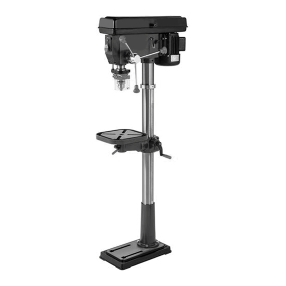
Page 8: Physical Features
CX618 – DRILL PRESS Physical Features A Digital Speed Readout I Pulley Cover Q Location Pin B ON/OFF Switch J Column R Bevel Scale C Depth Scale K Rack S Table Support Lock Handle D Chuck L Crank Handle T Speed Control Handle E Table M Column Base U LED Work light Switch... - Page 9 UNPACKING Unpack the drill press and all of its parts. Compare against the list below. Do not discard the carton or any packaging until the drill press is completely assembled. To protect the drill press from moisture, a protective coating has been applied to the machine’s surfaces. Remove this coating with a soft cloth moistened with kerosene or WD-40®.
-
Page 10: Assembly & Adjustments
ASSEMBLY AND ADJUSTMENTS WARNING: If any part is missing or damaged, do not plug the drill press in until the missing or damaged part is repaired or replaced. Tools needed for assembly Socket wrench Screwdriver Hammer and block of wood Assembly: The column assembly (column,... -
Page 11: Feed Handles
Thread the table lock handle (4) 1.) Carefully lift the drill press head assembly (1) and position it over the into the front of the table support column (2). bracket. 2.) Place the mounting opening (3) on the Align setscrew in crank handle with drill press head over the top of the flat, Figure 4, on pinion shaft and column. -
Page 12: Mounting The Drill Press
SPEED HANDLE (Fig. 7) 1. Insert the feed handle (1) into the Fig. 9 threaded opening on the speed hub (2). 2. Manually tighten handle into opening. Install the chuck 1. Inspect and clean the taper hole in the chick and the spindle. Remove all grease, oil and particles from the chuck and arbor surfaces with a clean cloth. -
Page 13: Removing The Chuck
RAISE OR LOWER THE TABLE (Fig. 12 ) 1. Loosen the support lock handle (1) and turn the crank handle (2) until the table is at the desired height. 2. Tighten the support lock handle before drilling. ROTATE THE TABLE (Fig. 12 ) 1. -
Page 14: Squaring The Table To The Drill Bit
ADJUST THE TABLE TO BE HORIZONTAL 1. Rotate the bolt (1) counter-clockwise with a wrench to loosen it. 2. Rotate the table to 0˚. 3. Hit the location pin (2) into the location hole in the table support with a hammer. 4. -
Page 15: Adjusting The Laser
ADJUSTING THE LASER WARNING: Do not stare directly at the laser beam. Please observe all safety rules. • Never aim the beam at a person or an object other than the workpiece. • Do not project the laser beam into the eyes of others. -
Page 16: Angular Play Of The Spindle
6. Tighten the two housing nuts. Do not overtighten the two nuts. If the nuts are tightened too much, the movement of the spindle and feed handles will become sluggish. REPLACING THE BELT WARNING: Disconnect the drill press from the power source before replacing ANGULAR “PLAY”... - Page 17 The laser switch (4) is located below the ON/OFF switch on the right. DRILL PRESS ON/OFF SWITCH (Fig 19) 1. To turn the drill press ON, insert the yellow safety key (1) into the switch housing (2). As a safety feature, the switch cannot be turned ON without the POSITION THE TABLE AND safety key.
- Page 18 might stop the motor, cause the belt to slip, force the workpiece loose, or break the drill bit. Practice with scrap material to get the feel of the machine before attempting to do any drilling operation. ADJUST THE DRILLING DEPTH (Fig.
-
Page 19: Drilling Speeds
3. Determine the drill depth for this workpiece. 4. Rotate the depth knob (2) until it is aligned with the desired depth mark (3) (for example, 1”) on the gauge scale. 5. The chuck will be stopped at the distance selected on the depth scale. WORKPIECE METHOD (Fig. - Page 20 twisting, or shifting causes a rough drill • Feeding too rapidly might stall the hole, and increases the potential of drill motor, cause the belt to slip, damage bit breakage. the workpiece, or break the drill bit. • Never hold a metal workpiece with •...
-
Page 21: Maintenance
position (seen below in the “Recommended Working Speeds” chart) depending on the RPM range needed. Retighten the spindles using the Lock Handle and then shut the belt cover. WARNING: Do not manually adjust belt position on the spindles when machine is MAINTENANCE WARNING: For your safety, turn the switch off and remove the plug from the power... -
Page 22: Troubleshooting
PROBLEM CAUSES SOLUTIONS Noisy operation 1) Incorrect belt tension 1) Adjust the belt tension (See 2) Dry spindle REPLACE THE BELT section) 3) Loosed spindle pulley 2) Lubricate the spindle 4) Loosed motor pulley 3) Tighten the retaining nut on the pulley insert 4) Tighten the set screw on the side of the motor pulley...
Need help?
Do you have a question about the CS Series and is the answer not in the manual?
Questions and answers