Table of Contents
Advertisement
Quick Links
Advertisement
Table of Contents

Related Manuals for Craftex CX12HC


Summary of Contents for Craftex CX12HC
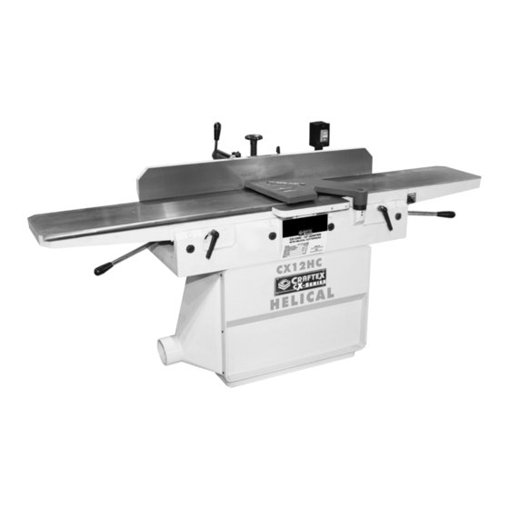
- Page 1 MODEL CX12HC 12" JOINTER WITH HELICAL CUTTERHEAD USER MANUAL Version 1.0...
-
Page 2: Table Of Contents
TABLE OF CONTENTS General Safety Instructions ............3 Specific Safety Instructions ............4 CX12HC ..................5 Physical Features ..............6 Set Up ..................7 Unpacking ................. 7 Proper Grounding ..............8 Assembly ................... 9 Basic Controls ................10 Test Run..................10 Fence Adjustment..............11 Infeed Table Adjustment............12... -
Page 3: General Safety Instructions
GENERAL SAFETY INSTRUCTIONS Extreme caution should be used when operating all power tools. Know your power tool, be familiar with its operation, read through the owner’s manual and practice safe usage procedures at all times. ALWAYS read and understand the knives or making other adjustments or user manual before operating the repairs. -
Page 4: Specific Safety Instructions
OPERATIONS MUST CX12HC. If you fail to do so, serious performed with the guards in place to injury could occur. ensure safety. WARNING! The safety instructions given above can not be complete because the environment in every shop is different. -
Page 5: Cx12Hc
FEATURES MODEL CX12HC - 12” JOINTER WITH HELICAL CUTTERHEAD As part of the growing line of Craftex woodworking equipment, we are proud to offer the CX012HC, an 12” Jointer with Helical Cutterhead. By following the instructions and procedures laid out in this user manual, you will receive years of excellent service and satisfaction. The CX12HC is a professional tool and like all power tools, proper care and safety procedures should be adhered to. -
Page 6: Physical Features
CX12HC PHYSICAL FEATURES Fence Fence Tilt Lock Lever Lock Lever Fence Outfeed Adjustment Table In-feed Knob Fence Tilt ON/OFF Table Handle Switch Depth Fence Scale Infeed Table Adjustment Lever Outfeed Table Adjustment Lever 4” Dust Cutterhead Hood Guard Infeed Outfeed... -
Page 7: Setup
WARNING! The hardware (screws, washers & etc) CX12HC is a heavy machine. Do not might be shipped in a plastic bag. After the over-exert yourself. Use fork truck or machine has been un-packed, check that other devices for safe moving. -
Page 8: Proper Grounding
CX12HC is for use on a normal 110 volt In case if you really find it necessary to use circuit. Make sure that the machine is... -
Page 9: Assembly
Insert the cutterhead guard shaft and use ASSEMBLY the set screws to tight it. See figure-10. Make sure the cord is disconnected from the power source. Install the fence assembly to the rear of the cabinet by aligning the fence mounting holes with the holes on the cabinet and tighten the cap screws to secure the fence in position. -
Page 10: Basic Controls
BASIC CONTROLS TEST RUN The basic controls of the jointer are shown Once you have assembled your machine in the figure below. Use this figure and read completely, it is then time for a test run to the text to know what the basic controls of make sure that the machine works properly your machine are. -
Page 11: Fence Adjustment
Figure-8 Fence tilt controls FENCE POSITIVE STOPS The CX12HC fence is equipped with positive stops at the most common fence positions (90° and 45° right left). Loosen the lock lever. -
Page 12: Infeed Table Adjustment
Tilt the fence inward as far as possible and INFEED TABLE use a combination square to check if the ADJUSTMENTS fence is tilted 45° inward to the table. To raise or lower the infeed table, loosen If an adjustment is necessary, loosen the the table lock lever. -
Page 13: Outfeed Table Adjustment
It may be necessary to adjust the positive stops. Loosen the two locknuts shown in figure-16 when moving the table up or down. Figure-14 Infeed table positive stop bolts Retighten locknuts. We recommend that the height of the infeed Figure-16 Outfeed table positive stops table to be adjusted so that the table at its highest point will be 1/2mm below the Turn the bolts and when the table is exactly... -
Page 14: Winding The Cutterhead Guard
WINDING THE WORKPIECE INSPECTION CUTTERHEAD GUARD Before cutting any wood, make sure to inspect the workpiece for the nails, staples, The cutterhead guar must be checked to small pieces of stone or metal and any see if it works properly. other object which is dangerous to come on contact with the blade. -
Page 15: Connecting To Adust Collector
DUST COLLECTOR When surface planing on a jointer, set the cutting depth to 1/32” and make sure the CX12HC features a 4” diameter dust ports fence is set to 90°. Place the concave face to connect to a dust collector. When... -
Page 16: Bevel Cutting
BEVEL CUTTING EDGE JOINTING Bevel cutting is the cutting operation to cut Edge jointing is to make the edge of the a desired angle on the edge of the work stock flat and suitable for joinery or piece. finishing. To edge joint on the jointer set the cutting depth to 1/16”... -
Page 17: Maintenance
To adjust or replace the carbide inserts, Since all the bearings are sealed and disconnect the machine from the power permanently lubricated on the CX12HC, source and remove the cutter head guard to you do not need to lubricated them. -
Page 18: Replacing And Tensioning V-Belts
REPLACING AND TENSIONING V-BELTS The jointer comes with two V-belts installed and properly tensioned. TO REPLACE THE V-BELTS: Disconnect the cord from the power source. Loosen the knob and pull the latch upwards. Open the rear cabinet door to access the V-belts. Figure-21 Removing the carbide inserts Loosen the lock nuts shown in figure-23 to Clean all the dust and debris on the cutter-... -
Page 19: Parts Breakdown & Parts List
FENCE PARTS BREAKDOWN... - Page 20 FENCE PARTS LIST DESCRIPTION SPRING PIN LOCK HANDLE HEX NUT FLAT WASHER HEX HD SCR HEX HD SCR HEX NUT FLAT WASHER HEX SOC SET SCR SUPPORT GUID BLOCK KNOB HEX SOC HD SCR HANDLE ROD HAND WHEEL HEX NUT HEX SOC SET SCR FENCE ADAPTER...
- Page 21 TABLE PARTS BREAKDOWN...
- Page 22 TABLE PARTS LIST DESCRIPTION OUTFEED TABLE TABLE LIP LOCK WASHER HEX SOC HD SCR SHAFT INFEED TABLE TABLE LIP HEX SOC HD SCR LOCK WASHER RABBET LEDGE HEX SOC HD SCR LOCK WASHER DEPTH LABEL RIVET FLAT WASHER CHEESE HD SCR DUST DEFLECTOR HEX SOC HD SCR BLOCK...
- Page 23 CABINET PARTS BREAKDOWN...
- Page 24 CABINET PARTS LIST LOCK WASHER DESCRIPTION SMALL STRAIN HEX SOC PAN HD RELIEF CROSS PAN HD SCR DUST HOOD FLAT WASHER DUST CHUTE MAGNETIC SWITCH COVER 434A CROSS PAN HD SCR HEX SOC PAN M5X20 HD SCR SWITCH PLATE CABINET EXT.
- Page 25 BASE PARTS BREAKDOWN...
- Page 26 BASE PARTS LIST REF DESCRIPTION SCR.(LEFT THREAD) GUARD HEX NUT WARNING LABEL LH BEARING COVER WARNING LABEL HEX SOCK HD SCR FLAT HD SCR HEX HD SCR SPECIAL WASHER HEX SOC SET SCR HEX SOC SET SCR BASE ADAPTOR HEX SOC SET SCR SPRING FLAT WASHER SHAFT COLLAR...
- Page 27 HEX.KEY(3MM) OPEN END WRENCH(17-19MM) OPEN END WRENCH(12-14MM) OPEN END WRENCH(10-12MM) LONG T- HEX.KEY(4MM)
-
Page 28: Warranty
This warranty shall not apply to consumable products such as blades, bits, belts, cutters, chisels, punches etceteras. Craftex shall in no event be liable for injuries, accidental or otherwise, death to persons or damage to property or for incidental contingent, special or consequential damages arising from the use of our products.
Need help?
Do you have a question about the CX12HC and is the answer not in the manual?
Questions and answers