Table of Contents
Advertisement
Quick Links
Advertisement
Table of Contents

Related Manuals for Craftex CT024N


Summary of Contents for Craftex CT024N
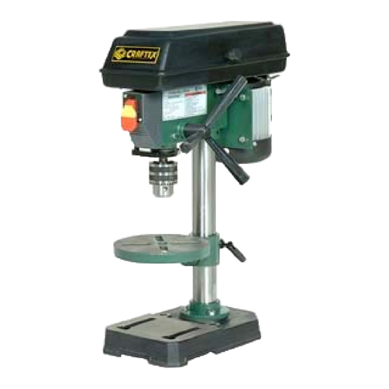
- Page 1 OWNER’S MANUAL CT024N – 8” DRILL PRESS...
-
Page 2: Table Of Contents
INDEX GENERAL SAFETY INSTRUCTIONS PAGE 3 SPECIFIC SAFETY INSTRUCTIONS PAGE 4 Features PAGE 5 Electrical Information PAGE 6 Unpacking & Cleaning PAGE 7 Assembly Base to Column PAGE 8 Drill Press Head to Column PAGE 9 Feed Handle PAGE 9 Pulley Cover PAGE 10 Mounting the Drill Press... -
Page 3: General Safety Instructions
GENERAL SAFETY INSTRUCTIONS EXTREME CAUTION SHOULD BE USED IN OPERATING ALL POWER TOOLS. KNOW YOUR POWER TOOL, BE FAMILIAR WITH ITS OPERATION. READ THE OWNER’S MANUAL AND PRACTICE SAFE USAGE PROCEDURES AT ALL TIMES. CONNECT your machine ONLY to the matched and specified power source. WEAR SAFETY GLASSES, HEARING PROTECTION and SAFETY SHOES when operating heavy machinery. -
Page 4: Specific Safety Instructions
SPECIFIC SAFETY INSTRUCTIONS Always make certain that you clamp down any object that you are drilling into. When drilling, make sure that you are using the correct speed for the material being drilled. Clear the drill press table of all objects before turning the tool on. Keep hands and fingers safely away from the spinning drill bits. -
Page 5: Features
DRILL PRESS FEATURES As part of the growing line of Craftex woodworking equipment, we are proud to offer the CT024N Drill Press. The Craftex name guarantees Craft Excellence. By following the instructions and procedures laid out in this owner’s manual, you will receive years of excellent service and satisfaction. -
Page 6: Electrical Information
In the event of a malfunction or breakdown, grounding provides the path of least resistance for electrical current and reduces the risk of electrical shock. This tool is equipped with an electrical cord that has an equipment grounding conductor and a grounding plug. The plug MUST be plugged into a matching outlet that has been properly installed and grounded in accordance with ALL local codes and ordinances. - Page 7 Carefully unpack your drill press and all of its parts. Compare the carton contents with the illustration below. Do not discard any packing material until the drill press is completely assembled and operating properly. Your drill press and some of its parts have been coated with a protective lubricant that should be removed before the machine is assembled.
-
Page 8: Assembly
ASSEMBLY BASE TO COLUMN Select the base and the drill press column from the loose parts. Select the four bolts from the parts bag. Align the holes of the post flange to the threaded holes in the base. Insert the bolts and tighten securely. -
Page 9: Drill Press Head To Column
ASSEMBLY DRILL PRESS HEAD TO COLUMN. Lift the drill press head carefully and position it over the column. The column fits into the drill press mounting hole. Make certain the mounting hole is properly seated on the column. Line the drill press head up with the table and base and then tighten the two set-screws using the supplied hex wrench. -
Page 10: Pulley Cover
ASSEMBLY PULLEY COVER Insert washer and screw through the hole in the pulley cover, thread the knob onto the screw and then tighten. MOUNTING THE DRILL PRESS Your drill press must be securely fastened to prevent the machine from tipping, sliding or walking during operation. -
Page 11: Adjustments
Adjustments CHANGING SPINDLE SPEEDS Disconnect the drill press from its power source. Open the pulley cover. Loosen the slide bar knob Move the motor to the front to loosen the tension on both belts. Relocate the belts to the pulley steps appropriate to the required spindle speed To tighten the belt tension, move the motor toward the rear of the drill press. -
Page 12: Drilling Depth
ADJUSTMENTS DRILLING DEPTH Your drill press has been equipped with a new type depth adjustment. To set the depth stop, loosen the depth locking nuts and rotate them to the desired depth as indicated on the scale. SPINDLE RETURN SPRING The spindle is equipped with an auto-return mechanism. -
Page 13: Operation
OPERATION Note: As with any new piece of equipment, the owner/operator should use scrap material in order to become accustomed to it. DRILLING SPEEDS The following is intended to be a general rule-of-thumb, not specific information. Important drilling speed factors are the type of material, hole size, the type of drill bit/cutter and the desired cut quality. -
Page 14: Maintenance
MAINTENANCE Disconnect the Power Cord before Working on the Machine Although machines such as this drill press are designed to work in wood shops and metal shops, sawdust and metal shavings are not friendly to electrical motors. The owner should routinely (once a month) blow out or vacuum metal shavings and sawdust from around the motor cover, the pulley housing, the drill press table and other surfaces. -
Page 15: Schematic Diagram
CT024N – 8” Drill Press SCHEMATIC DIAGRAM... -
Page 16: Parts List
CT024N – 8” Drill Press... -
Page 17: Warranty
CRAFTEX 2 YEAR LIMITED WARRANTY Craftex warrants every product to be free from defects in materials and agrees to correct such defects where applicable. This warranty covers two years for parts and 90 days for labour (unless specified otherwise), to the original purchaser from the date of purchase but does not apply to malfunctions arising directly or indirectly from misuse, abuse, improper installation or assembly, negligence, accidents, repairs or alterations or lack of maintenance.
Need help?
Do you have a question about the CT024N and is the answer not in the manual?
Questions and answers