Table of Contents
Advertisement
Advertisement
Table of Contents

Subscribe to Our Youtube Channel
Related Manuals for Craftex CT201


Summary of Contents for Craftex CT201
- Page 1 CT200 & CT201 6” & 8” JOINTERS With SPIRAL CUTTER-HEADS...
-
Page 2: Table Of Contents
INDEX General Safety Instructions ............... 3 Specific Safety Instructions ............... 4 CT200-6" Jointer Features ..............5 CT201-8" Jointer Features ..............6 Physical Features................7 Proper Grounding................8 Setup ....................9 Un-packing ..................9 Assembly ..................10 Mobile Base ..................10 Installing Jointer to the Stand............ -
Page 3: General Safety Instructions
GENERAL SAFETY INSTRUCTIONS Extreme caution should be used when operating all power tools. Know your power tool, be familiar with its operation, read through the owner’s manual and practice safe usage procedure at all times. CONNECT your machine ONLY to NEVER reach over the table when the matched and specific power the tool is in operation. -
Page 4: Specific Safety Instructions
CT200-6” & CT201-8” Jointers Specific Safety Instructions Always lock the mobile base Maintain the proper relationship of before operating the machine. in-feed and out-feed table surfaces IF you are not familiar with the and the cutter head knife path. operations of a jointer, you should... -
Page 5: Ct200-6" Jointer Features
FEATURES MODEL CT200-6” JOINTER WITH SPIRAL CUTTERHEAD As part of the growing line of Craftex woodworking equipment, we are proud to offer the CT200- 6” Jointer with Spiral Cutter-Head. The Craftex name guarantees Craft Excellence. By following the instructions and procedures laid out in this owner’s manual, you will receive years of excellent service and satisfaction. -
Page 6: Ct201-8" Jointer Features
FEATURES MODEL CT201-8” JOINTER WITH SPIRAL CUTTERHEAD As part of the growing line of Craftex woodworking equipment, we are proud to offer the CT201- 8” Jointer with Spiral Cutterhead. The Craftex name guarantees Craft Excellence. By following the instructions and procedures laid out in this owner’s manual, you will receive years of excellent service and satisfaction. -
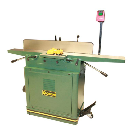
Page 7: Physical Features
PHYSICAL FEATURES Fence Tilt Lock ON/OFF Switch Out-Feed Fence Fence Tilt Knob Table Lock Cutter-Head In-Feed Guard Table Fence Out-feed Table Out-Feed Lock Table Adjustment Lever Out-Feed Table In-Feed Depth Adjustment Table Scale Lever Lock 4” Dust Hood Mobile Base... -
Page 8: Proper Grounding
Proper Grounding e machine is pre-wired to be used with a 0-volt (CT200) or 240-volts (CT201) wer supply. Ensure the cord is plugged to a grounded power outlet. To prevent possible electrical hazards, have a qualified electrician ensure that the line is properly wired. -
Page 9: Setup
Unpacking The CT200 is properly packaged in 2 T200/CT201 is a heavy m achine. Do boxes and CT201 is in a wooden crate ot over-exert yourself. For safe moving for safe transportation. When unpacking, method get the help of assistant. -
Page 10: Assembly
ASSEMBLY Installing the Mobile Base heavy, so a strong rigid mobile base has To install the mobile base of your jointer been provided). ou need to lay the stand on its side so that you can have access to the nderneath of the stand. -
Page 11: Extension Table
ASSEMBLY Installing the Extension Table stalling the Fence ake the extension table and locate the o install the fence first you have to holes for the cap screws on the in-feed install the fence carriage to the table table. Attach the extension table to the stand using wa shers and cap screws in-feed table finger tightening the cap... -
Page 12: Fence
ASSEMBLY Installing Tilt Knob and Fence stalling the Cutter-Head Guard Lock Handle To install the cutter-head guard move the The tilt lever is used to tilt the fence up fence backward so that you ha ve enough and down to your desired angle. pace. -
Page 13: Dust-Hood
ASSEMBLY Installing the Dust Hood Attach the dust hood to the side on the stand assembly by using the he x bolts, at washers and hex nuts provided. (See Figure 9) Figure 10: Installing pedestal switch Installing the V-Belt Your machine is provided with a V-belt that goes around the motor pulley and the cutterhead pulley. -
Page 14: Operations & Adjustments
OPERATIONS AND ADJUSTMENTS Basic Controls TEST RUN The basic controls of the jointer are Once you have assembled your machine shown in the figure below. Use this figure completely, then it is time for a test run to and read t he text to know what the basic make sure that the machine works controls of your machine are. -
Page 15: Surface Planing
OPERATIONS AND ADJUSTMENTS Surface Planing dge Jointing When surface planing on a jointer, make Edge jointing is to make the edge of the ure the stock is free of nails, staples or tock flat a nd suitable for joinery or any other object. -
Page 16: Bevel Cutting
OPERATIONS AND ADJUSTMENTS Bevel Cutting It is recommended to set the cutting Bevel cutting is the cutting operation to depth between 1/16” and 1/8” when cut a desired angle on the edge of the doing bevel cutting. work piece. Now, set the fence to your desired angle To perform bevel cutting operation on a and start the jointer. -
Page 17: Inspecting The Cutter-Head
OPERATIONS AND ADJUSTMENTS Inspecting the Cutter-Heads The cutter-heads are supposed to be at the same height with each other and with the out-feed table. If one of the carbide inserts is high er than the others, you will get a poor result while doing any cutting operation. - Page 18 OPERATIONS AND ADJUSTMENTS Table Parallelism Now, place the straightedge halfway across the in-feed table and halfway over For the best cutting results, the in-feed the out-feed table to adjust the in-feed and out-feed tables of the jointer must be table with the out-feed table. paralleled to the cutter-head and to each other.
-
Page 19: Setting Out-Feed Table Height
OPERATIONS AND ADJUSTMENTS Setting the Out-feed Table Height Setting the In-feed Table Height The positive stop bolts located at the The height of the out-feed table must be back of the machine allows you to adjust qual to the height of the cutter-head the height of the in-feed table. -
Page 20: Parts Breakdown & Lists
CT200 TABLE PARTS BREAKDOWN... - Page 21 CT200 CABINET PARTS BREAKDOWN...
-
Page 22: Ct201 Parts Breakdown
CT201 TABLE PARTS BREAKDOWN... - Page 23 CT201 CABINET PARTS BREAKDOWN...
- Page 24 CT200-6” JOINTER CABINET PARTS LIST REF# PART# DESCRIPTION REF# PART# DESCRIPTION M6X10MM HEX SOC SET SCR GB78 M5X16 CROSS PAN HD SCR. GB818 5X30MM KEY GB1096 5MM FLAT WASHER GB96 MOTOR 1HP BACK SIDE PANEL M8X25MM HEX SOC HD SCR MB15- GB70 8MM LOCK WASHER...
- Page 25 CT200-6” JOINTER TABLE PARTS LIST SOC HD SCR HANDLE DJ-001 STUD KNOB DJ-002 DJ-018 BUSHING INDEX PIN ASSY,INCL: DJ-003 DJ-019 (DIN 1481)M 3X20MM SPRING SHAFT DJ-004 (DIN 914)M6X16MM HEX SOC GB879 SET SCR SPRING GB80 DJ-020 (DIN 913)M8X10MM HEX SOC (DIN 933)M6X25MM HEX HD SET SCR GB80...
- Page 26 HD SCR EXTENSION SPRING DJ-060A (DIN 91 2)M8X80MM HEX SOC CHIPBREAKER DJ-055A HD SCR GB70 6MM FLAT WASHER GB97 (DIN 79 80)8MM LOCK (DIN 933)M6X12MM HEX HD WASHER GB93 GB5782 BEARING BL OCK LEFT DJ-034A FLAT WASHER DJ-011 BALL BEARING KNOB DJ-063A SPIRAL CUTTERHEAD...
- Page 27 CT201-8” JO T IN ER CABINET PAR S T LIST DESC RIPTION REF# PART# SCRIPTION M8X25MM SOC HD SCR M5X16MM PAN HD 5MM FLAT WASHER GB70 GB96 8MM LOCK WASHER PANEL GB93 M6 HEX NUT M6X12MM FLANGE SCR GB6170 6MM FLAT WASHER...
- Page 28 TABLE PARTS LIST REF# PART# DESCRIPTION REF# PART# DESCRIPTION KNOB INDES PIN ASSEMBLY DJ-001 DJ-019 STUD 3X20MM ROLL PIN DJ-002 GB879 BUSH SPRING DJ-003 DJ-020 ECCENTRIC SHAFT M6X25 HEX BOLT DJ-004 GB5782 M6X16MM HEX SOC SET M6 HEX NUT GB6170 SCR.
- Page 29 60104 BEARING CHIP BREAKER DJ-055B SPIRAL CUTTERHEAD M6 FLAT WASHER GB97 6X35 KEY M6X12MM HEX HD SCR DJ-041 GB5782 FLAT 47MM INT. RET. RING GB893 8.4X30X5 DJ-011 60105 BEARING TABLE LOCK LEVER DJ-063B BEARING BLOCK RH DJ-035B ECCENTRIC BUSHING DJ-056B CUTTER HEAD PULLEY DJ-042B TABLE SHAF...
-
Page 30: Warranty
Craftex reserves the right to spect any returned item before a refund or replacement may be issued.
Need help?
Do you have a question about the CT201 and is the answer not in the manual?
Questions and answers