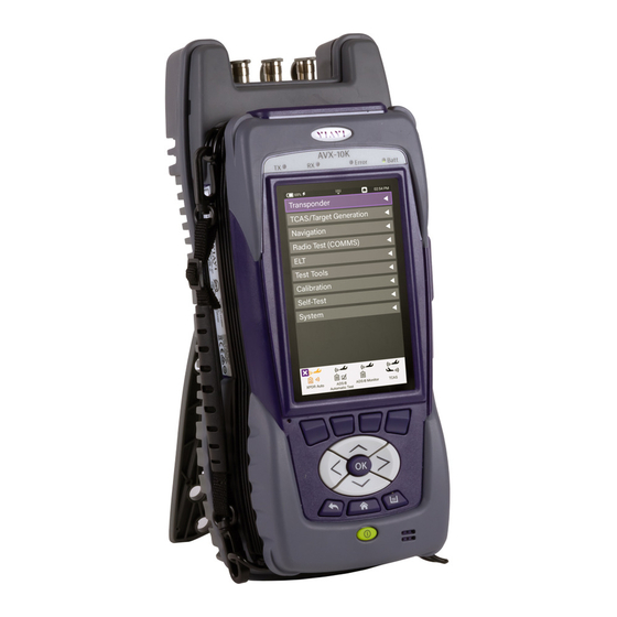
Viavi AVX-10K Operation Manual
Flight line test set
Hide thumbs
Also See for AVX-10K:
- Operation manual (147 pages) ,
- Getting started manual (31 pages) ,
- Getting started manual (21 pages)
Table of Contents
Advertisement
Quick Links
Advertisement
Table of Contents

Related Manuals for Viavi AVX-10K


Summary of Contents for Viavi AVX-10K
- Page 1 AVX-10K Flight Line Test Set Operation Manual...
- Page 2 AVX-10K Flight Line Test Set Operation Manual 22135254 / Rev. 004 VIAVI Solutions 1-844-GO-VIAVI www.viavisolutions.com...
- Page 3 Copyright/Trademarks © Copyright 2024 VIAVI Solutions, Inc. All rights reserved. No part of this guide may be reproduced or transmitted, electronically or otherwise, without written permission of the publisher. VIAVI Solutions and the VIAVI logo are trademarks of VIAVI Solutions Inc.
- Page 4 The authority to operate this equipment is conditioned by the requirements that no modifications be made to the equipment unless the changes or modifications are expressly approved by VIAVI. ALERT •...
- Page 5 VIAVI has established a take-back processes in compliance with the EU Waste Electrical and Electronic Equipment (WEEE) Directive, 2012/19/EU, and the EU Battery Directive, 2006/66/EC. Instructions for returning waste equipment and batteries to VIAVI can be found in the WEEE section of VIAVI’s Standards and Policies web page.
- Page 6 Ordering information This manual is a product of the VIAVI Technical Publications Department, issued for use with the AVX-10K Flight Line Test Set. The PDF format of this manual is available on the VIAVI product website.
- Page 7 Open Source Disclaimer - IMPORTANT READ CAREFULLY The AVX-10K Flight Line Test Set includes third party software licensed under the terms of separate open source software licenses. By using this software you agree to comply with the terms and conditions of the applicable open source software licenses.
- Page 8 CE Compliant CE Label indicates item meets the requirements of the applicable European Directives. Fuse Symbol Indicates a fuse location (AC or DC). 22135254 AVX-10K Operation Manual Rev. 004 January, 2024 Safety - 7...
- Page 9 • Do not crush, incinerate or dispose of in normal waste. • Do not short circuit or force discharge since this might cause the battery to vent, overheat or explode. Rev. 004 AVX-10K Operation Manual 22135254 Safety - 8 January, 2024...
- Page 10 Electronic Equipment (WEEE) Directive, 2012/19/EU, and the EU Battery Directive, 2006/66/EC. Information and instructions for returning waste equipment and batteries to VIAVI can be found on the VIAV website in the WEEE section of VIAVI’s Standards and Policies web page at: VIAVI’s Standards and Policies web page.
- Page 11 Contact VIAVI for packaging and labeling instructions. Mise en Garde Cet appareil contient une batterie au lithium-ion et peut nécessiter un emballage spécial et un étiquetage externe lors de l'expédition. Contactez VIAVI pour l'emballage et les instructions étiquetantes. Rev. 004 AVX-10K Operation Manual...
- Page 12 Mise en Garde Ne surchargez pas les connecteurs d'entrée. Reportez-vous aux spécifications du produit ou à la fiche technique du produit pour connaître les valeurs d'entrée maximales. 22135254 AVX-10K Operation Manual Rev. 004 January, 2024 Safety - 11...
- Page 13 • Connectez uniquement l'adaptateur secteur / cordon d'alimentation à la tension secteur appropriée indiquée sur l'étiquette des caractéristiques nominales. • N'utilisez pas l'adaptateur / cordon d'alimentation secteur s'il semble endommagé ou s'il a été modifié. Rev. 004 AVX-10K Operation Manual 22135254 Safety - 12 January, 2024...
- Page 14 électrique. L’énergie résiduelle est dans les limites des exigences de sécurité approuvées. Par contre, un léger choc électrique peut être ressenti si l’on touche les broches de la prise immédiatement après son débranchement. 22135254 AVX-10K Operation Manual Rev. 004 January, 2024 Safety - 13...
- Page 15 Battery Safety Information The battery included with the product should only to be used with VIAVI AVX-10K Flight Line Test Set. Battery Storage, Handling and Disposal CAUTION • To avoid risk of fire and burns, do not tamper with the batteries.
- Page 16 Qualified Service Personnel. Mise en Garde Cet appareil ne contient pas de pièces pouvant être entretenues par l’utilisateur. L’entretien doit seulement être effectué par du personnel de service qualifié. 22135254 AVX-10K Operation Manual Rev. 004 January, 2024 Safety - 15...
- Page 17 • Connect the equipment into an outlet on a circuit different from that to which the receiver is connected. • Use properly shielded and grounded cables and connectors in order to meet FCC emission limits. Rev. 004 AVX-10K Operation Manual 22135254 Safety - 16 January, 2024...
- Page 18 Les utilisateurs de cet équipment doivent examiner soigneusement tout fonctionnement provoquant le rayonnement d'un signal (direct ou indirect) et ils doivent prendre les dispositions nécessaires afin d'eviter des problémes potentiels d'interferénces sur les communications. 22135254 AVX-10K Operation Manual Rev. 004 January, 2024 Safety - 17...
- Page 19 This page intentionally left blank.
-
Page 20: Table Of Contents
Overview AVX-10K ........ - Page 21 2.10.5 Updating Test Set Software ........2-34 2.10.6 Updating Software Options on AVX-10K ......2-36 Chapter 3 Test Application Common Settings/Steps .
- Page 22 Run COMM High Frequency (HF) Single Side Band (SSB) Receive ..7-11 7.5.2 Run COMM High Frequency (HF) Single Side Band (SSB) Generate ..7-12 22135254 AVX-10K Operation Manual Rev. 004 January, 2024 TOC - 3...
- Page 23 9.5 Editing a Guided Test ..........9-13 9.6 Porting a Guided Test to another AVX-10K ......9-17 Chapter 10 Test Tools .
- Page 24 F.1 Appendix F. Standard Accessories and Procedures ..... . . F-2 Rev. 004 AVX-10K Operation Manual 22135254 TOC - 5...
- Page 25 This page intentionally left blank.
- Page 26 Figure 2-18 . . AVX-10K Network Address ....... . .
- Page 27 Figure 3-24 . . USB File Browser Icon........3-17 Rev. 004 AVX-10K Operation Manual 22135254...
- Page 28 Figure 5-9 . . . Target Gen Test Configuration....... . 5-9 22135254 AVX-10K Operation Manual Rev. 004...
- Page 29 Figure 7-8 . . . VHF COMM Frequency Modulation (FM) Generate ....7-10 Figure 7-9 . . . COMM High Frequency (HF) Single Side Band (SSB) Receive ..7-11 Rev. 004 AVX-10K Operation Manual 22135254 LOF - 4...
- Page 30 Figure 10-3 . . VSWR Calibration Button ........10-4 22135254 AVX-10K Operation Manual Rev. 004...
- Page 31 Figure F-3 . . . VSWR Calibration Kit – Short and 50-ohm Load ....F-3 Figure F-2 . . . AVX-10K Accessories with Transit Case ......F-3 Figure F-4 .
- Page 32 Table 7-2 ..VHF COMM Amplitude Modulation (AM) Receive Settings ....7-6 Table 7-3 ..VHF COMM Amplitude Modulation (AM) Generate Settings ....7-7 22135254 AVX-10K Operation Manual Rev. 004 January, 2024...
- Page 33 Table A-1 ..AVX-10K Test Limit Results ......
- Page 34 Contact Information ..........iii 22135254 AVX-10K Operation Manual Rev 004...
- Page 35 AVX-10K test set. Read this manual carefully before setting up or operating the instrument. Product Nomenclature The following terms may be used in this Operations Manual to refer to the AVX-10K Flight Line Test Set. •...
- Page 36 Preface Contact Information Contact VIAVI Customer Service for technical support or with any questions regarding this or any other VIAVI products. • Phone: 1-844-GO-VIAVI • Email: Techsupport.Avcomm@viavisolutions.com For the latest information, go to: https://www.viavisolutions.com/en-us/services-and-support/support/technical-assistance 22135254 AVX-10K Operation Manual Rev 004...
- Page 37 Preface This page intentionally left blank. Rev 004 AVX-10K Operation Manual 22135254 Preface - iv January 2024...
- Page 38 Overview AVX-10K Chap ter 1 This chapter provides a general overview of the AVX-10K. Topics discussed in this chapter include the following: • General Information ..........1-2 •...
-
Page 39: Chapter 1 Overview Avx-10K
Chapter 1 Overview AVX-10K General Information General Information The AVX-10K Flight Line Test Set is a portable test instrument that provides a single instrument test solution for performing a variety of flight line testing including Transponder, TCAS, Target Generation, Navigation, Communications (COMMS), and ELT testing. - Page 40 General Information VIAVI's Smart Access Anywhere application can be downloaded from the VIAVI website: https://www.viavisolutions.com/en-us/software-download/smart-access-anywhere-saa-so ftware. This software can be used to remotely connect to the AVK-10K when the AVX-10K is connected to the Internet. Figure 1-2 Mobile Tech Application...
-
Page 41: Principles Of Operation
Figure 1-3 StrataSync™ Dashboard Principles of Operation The AVX-10K consists of the VIAVI OneExpert base platform and the AVX Application Module. The VIAVI OneExpert base platform supports system functionality such as network connectivity, system updates and power management. The AVX Application Module manages the device’s RF test and measurement functions. -
Page 42: Platform And System Features
• Dual Ethernet and 2.0 USB ports • WiFi and GPS receivers • Smart Access Anywhere - allowing VIAVI tech support to troubleshoot set up and test issues remotely • Sleep Mode (battery power saving mode) 22135254 AVX-10K Operation Manual... -
Page 43: Features And Capabilities
This information is readily available on your StrataSync™ account. In the event a software update is needed, AVX-10K software can be upgraded in the field using VIAVI's StrataSync™ application (via WiFi or a direct network connection) or by downloading the latest firmware from StrataSync™... - Page 44 Press the RUN soft key and follow the prompts as directed. A cable will be needed for External Loopback test. This cable is supplied with each AVX-10K. d. When Self-Test has completed running all tests, verify that all portions of the test...
- Page 45 Chapter 1 Overview AVX-10K First Time Use and Self-Test have passed. If any portion of Self-Test fails, please contact VIAVI Customer Service. Rev 004 AVX-10K Operation Manual 22135254 1 - 8 January 2024...
- Page 46 Turn the Test Set OFF 1. Press and hold the Power button ~1 second; release the Power Button when the Front Panel displays a white screen with the VIAVI logo. 2. The device performs a series of power-down processes and shuts down. •...
- Page 47 Chapter 1 Overview AVX-10K First Time Use and Self-Test This page intentionally left blank. Rev 004 AVX-10K Operation Manual 22135254 1 - 10 January 2024...
-
Page 48: Chapter 2 Setup, Control, And Operation
Setup, Control, and Operation Chap ter 2 This chapter describes how to Setup and Operate the AVX-10K. The topics discussed in this chapter are as follows: • Control and Operation ..........2-3 •... - Page 49 Updating Test Set Software........2-34 • Updating Software Options on AVX-10K ......2-36 Rev 004...
-
Page 50: Control And Operation
Control and Operation Control and Operation The AVX-10K Flight Line Test Set can be operated locally using the touchscreen, keypad or remotely using any mobile device with VIAVI's Mobile Tech application which is available at any online application store. Optionally, remote control of the AVX-10Kcan be accomplished via a VNC viewing application (such as Tight-VNC) from a laptop or PC. -
Page 51: Controls And Buttons
(UI). • OK Button The OK Button is used to accept/confirm a changed setting or to proceed to the next menu. Rev 004 AVX-10K Operation Manual 22135254 2 - 4 January 2024... - Page 52 • Function Hard Keys (10) select screen-specific options or to select menus associated with each key. The Function Hard Keys and UI Function Soft Keys perform the same functions. 22135254 AVX-10K Operation Manual Rev 004 January 2024 2 - 5...
-
Page 53: I/O Connectors
Chapter 2 Setup, Control, and Operation Hardware 2.2.2 I/O Connectors The AVX-10K is equipped with three TNC-type connectors on the AVX Application Module. These connectors support test and measurement functions. Figure 2-3 I/O Connectors CAUTION: Do not overload input connectors. Refer to the product data sheet for maximum input ratings. -
Page 54: Hand Strap Rings
• TX: Transmit Indicator LED blinks green when transmitting to the device under test. • RX: Receive Indicator LED blinks green when the AVX-10K is receiving input from the device under test. • Error: This LED is solid red indicates error and alarm conditions. The type of error varies depending on the application. -
Page 55: Display Screen
Remote Operation The AVX-10K test set can be operated remotely via the Mobile Tech application or optionally via a VNC connection using a VNC application running on a computer. It is also possible to connect remotely via the Smart Access Anywhere application provided by VIAVI. -
Page 56: Mobile Tech Application
2.3.1 Mobile Tech Application Figure 2-6 Mobile Tech Application VIAVI’s Mobile Tech app can be found in the Apple App Store or Google Play Store and can be run from any mobile device. This application can connect to the AVX-10K via Wireless or WIFI connection. You must have an active StrataSync™... - Page 57 If that ribbon is not available on your Home Screen, you will need to add it by going to System Settings, Home Screen and enabling the WiFi option. Figure 2-8 Home Screen WiFi Selection Rev 004 AVX-10K Operation Manual 22135254 2 - 10 January 2024...
- Page 58 Figure 2-9 WiFi Access Point Start Button You will then be able to connect your tablet or phone’s WiFi to the AVX-10K. Go to your device settings, enable WiFi and look for an SSID that starts with “VIAVI-ONX” and connect.
-
Page 59: Vnc Viewer
• A VNC viewing application must be installed on the computer • AVX-10K test set and computer (both devices must be connected to the same network). Configure the AVX-10K Remote Operation via Systems Settings using your own VNC password. This will be the password that the user of the VNC viewer software will need in order to gain access. -
Page 60: Smart Access Anywhere Application
Remote Operation When you run the VNC viewer software, you will need to know the IP Address of the AVX-10K test set. This can be found by launching the Network application in the System ribbon. Figure 2-11 IP Address & Network ID View the Device UI Remotely 1. -
Page 61: Figure 2-12
Chapter 2 Setup, Control, and Operation Remote Operation To enable SAA on the AVX-10K and generate a code, open the System Settings application in the System ribbon, click Remote Operation, then Smart Access Anywhere and VNC. Ensure that top entry (Enable Smart Access Anywhere) is enabled and click the ‘Connect to SAA Server’... -
Page 62: Figure 2-13
Figure 2-13 Smart Access Anywhere Application Once connected, click the Remote Screen Page button and the application will allow you to control the test set. Figure 2-14 Remote Screen Page 22135254 AVX-10K Operation Manual Rev 004 January 2024 2 - 15... -
Page 63: Http File Server
Figure 2-15 Session Button 2.3.4 HTTP File Server Enabling the HTTP File Server in the Remote Operation System Settings allows a user to transfer files directly from the AVX-10K using a web browser. Figure 2-16 Enable HTTP File Server Feature Rev 004... -
Page 64: Figure 2-17
Remote Operation An example of the web browser interface is shown here in Figure 2-17. To use this feature, simply type in the IPv4 Network address of the AVX-10K in the address bar of the browser – 10.170.170.58 is used here. -
Page 65: User Interface (Ui) Layout
The Shortcut panel at the bottom of the screen is used to provide quick access to frequently used functions. Figure 2-19 Home Screen Examples Rev 004 AVX-10K Operation Manual 22135254 2 - 18 January 2024... -
Page 66: Application Screen Layout
Active Connectivity Icons are shown at the top of the screen. When connected to the network via the LAN port, the network connection indicator will look like this: Figure 2-21 LAN Port Indicator 22135254 AVX-10K Operation Manual Rev 004 January 2024 2 - 19... -
Page 67: Figure 2-22
AC power supply. • Lock Indicator This is an indication that the system settings have been locked by the administrator of your AVX-10K. No setting parameters can be modified while in this state. Rev 004 AVX-10K Operation Manual... - Page 68 A red “X” is displayed when the device experiences a critical system error. A system generated error message will also be displayed in the Notification panel. • Function and Test Application Status 22135254 AVX-10K Operation Manual Rev 004 January 2024 2 - 21...
-
Page 69: Ui Navigation
Return to the previously viewed screen • Close a running function or application • Close a menu without making a selection • Exit and cancel a change being made to an alpha/numeric data field. Rev 004 AVX-10K Operation Manual 22135254 2 - 22 January 2024... -
Page 70: Selecting And Entering Parameters
< or > • Use the arrow navigation keys to highlight the desired item; press the OK button to confirm. When confirmed, the selection is activated and the menu closes. 22135254 AVX-10K Operation Manual Rev 004 January 2024 2 - 23... -
Page 71: Managing Application Shortcuts
To remove, touch and hold the application icon in the shortcut panel, drag and drop away from the shortcut panel, or move an application icon to the Shortcut panel placing it over one of the existing shortcuts. Rev 004 AVX-10K Operation Manual 22135254 2 - 24 January 2024... -
Page 72: Configuring System Settings
Chapter 2 Setup, Control, and Operation Configuring System Settings Configuring System Settings Figure 2-25 System Settings 22135254 AVX-10K Operation Manual Rev 004 January 2024 2 - 25... -
Page 73: Configuring System Settings (Cont.)
USB drive. Insert a USB drive with the provided or downloaded software update file into either of the USB ports on the side of the AVX-10K. Click the Force Software Update option and then click the Update button in the lower right corner. -
Page 74: Establishing Network Connections
• Save Location – This setting allows you to select where you want report files to be saved. They can be saved locally to the AVX-10K file folders or to a connected USB drive or to both, where applicable. •... -
Page 75: Establish Ethernet Connection
1. Using an Ethernet cable, connect the instrument to the LAN: • Connect one end of the Ethernet cable to the AVX-10K Ethernet connector located on the side panel and connect the other end of the Ethernet cable to the LAN. -
Page 76: Establishing A Wifi Connection
The WiFi option allows you to establish a WiFi connection to a wireless network to 1) Synchronize your instrument to the StrataSync™ server, 2) Export reports, screenshots (using FTP), or 3) Update the firmware on your instrument. 22135254 AVX-10K Operation Manual Rev 004 January 2024 2 - 29... - Page 77 NOTE: Hidden SSIDs are not currently supported. To connect, un-hide the SSID, connect the AVX-10K and re-hide the SSID or leave the SSID unhidden. Connecting to a WiFi Connection You can manually connect to any compatible WiFi network that is within range of your instrument, and for which you have authorized access (and a password for authentication).
-
Page 78: Establishing A Wireless Connection
2. Press the box next to Enabled. A checkmark appears. 3. Press Scan for devices. The instrument scans for Wireless devices, then lists the devices on the menu. 4. Select the device to connect. 22135254 AVX-10K Operation Manual Rev 004 January 2024 2 - 31... -
Page 79: Synchronizing To The Stratasync Server
• Uploading and storing of test reports, screen shots, and configurations To obtain the latest configuration settings, software options and updates, and ownership registration information, the AVX-10K can synchronize with a VIAVI server via the Internet. The synchronization also stores any user files stored on the unit to the StrataSync™... - Page 80 • If any upgrades are available, the user will be informed of the update availability and offered the choice to upgrade. • When synchronization is complete, the Status will indicate “Sync Complete”. The device may be disconnected from the server. 22135254 AVX-10K Operation Manual Rev 004 January 2024 2 - 33...
-
Page 81: Updating Test Set Software
3. Download the file to your PC. a. There are two files – The Software and the Release Notes. b. VIAVI Solutions advises reviewing the release notes prior to upgrading. c. The Software file is in .oxu format (approx. 200-300MB size) and needs no special file structure or unzipping. - Page 82 Establishing Network Connections 4. Prepare a USB Drive as FAT32 file format. a. VIAVI Solutions advise a freshly formatted USB Drive from a reputable manufacturer, preferably with no other files on it. 5. Copy the.oxu file from step 3 to the root directory of the USB Drive.
-
Page 83: Updating Software Options On Avx-10K
Figure 2-28 Available Software Options 3. Double-click on the option that you wish to deploy and select the AVX-10K that you wish to enable with this software option. Ensure that the serial number of the AVX-10K is the correct device. Click the checkbox to the left of the selected AVX-10K and choose “Deploy”... -
Page 84: Figure 2-29
Figure 2-30 Deploy Option Window NOTE: By selecting “Send an email”, this will send an Option Key to the registered email allowing you to download and install via USB. 22135254 AVX-10K Operation Manual Rev 004 January 2024 2 - 37... -
Page 85: Figure 2-31
5. You should receive a response indicating that the software option has been deployed. Go to the StrataSync application on the AVX-10K that the software option has been deployed to and press the Start key in the lower right corner. You will be asked if you want to deploy the selected option. -
Page 86: Figure 1-2
File Management ..........3-13 22135254 AVX-10K Operaton Manual Rev 004... -
Page 87: Chapter 3 Test Application Common Settings/Steps
3.1.1 Direct with Coupler Figure 3-1 Coupler Test Setup This is one of the more common test setup methods where the AVX-10K RF I/O port is cabled to a coupler which is then mounted over or clamped to an antenna. When using this setup, the cable loss as well as the coupler loss must be considered. - Page 88 Chapter 3 Test Application Common Settings/Steps Antenna Setups The AVX-10K can also be used to test the onboard equipment using the over-the-air test setup. When using this setup, the antenna gain, the height of the antenna and the distance from the antenna must be considered. These values can also be entered in the Setup tab.
-
Page 89: Direct To Uut
3.1.3 Direct to UUT Figure 3-5 Direct to UUT Test Setup On occasion, the AVX-10K may need to be directly connected to the UUT bypassing the antenna and cabling. When using this setup, only the cable loss will factor into the setup parameters. -
Page 90: Common Setup Parameters
Chapter 3 Test Application Common Settings/Steps Common Setup Parameters Common Setup Parameters There are settings that are duplicated across many applications within the AVX-10K. This section will detail those common settings of applicable test applications from the SETUP tab. These include: •... -
Page 91: Rf Port
NOTE: Top and Bottom settings are both available only when Diversity Test (an application-specific setting) is ON. Otherwise, only Bottom Antenna settings will be available. Figure 3-8 Antenna Settings Rev 004 AVX-10K Operaton Manual 22135254 3 - 6 January 2024... -
Page 92: Figure 3-10
Figure 3-9 Range and Height Value Determination Set Antenna Gain values for 1030 MHz and 1090 MHz located on the back of the RF flat panel antenna. Figure 3-10 Antenna Gain Values 22135254 AVX-10K Operaton Manual Rev 004 January 2024 3 - 7... -
Page 93: Cable Settings
When set to Auto, the test will interrogate the UUT and use the address in the reply as the UUT Address. NOTE: For the UUT to respond to a MODE S ALL-CALL, the aircraft must be in the airborne condition. Rev 004 AVX-10K Operaton Manual 22135254 3 - 8 January 2024... -
Page 94: Position Settings
(1090MHz emitters). Most often this should be left as DF17. The DF18 option is used for beacons placed on obstacles around airports or in vehicles that are travelling around aircraft. 22135254 AVX-10K Operaton Manual Rev 004 January 2024 3 - 9... -
Page 95: Recall Data Button
• Verify Unit Setup Configuration – when set to YES, this will cause a pop-up screen to appear after the RUN button is selected, allowing the user to verify the AVX-10K is set up correctly prior to running the test. Setting this to NO will disable this popup screen. -
Page 96: Figure 3-17
SAVE was performed. This is an optional way to view report data. Figure 3-17 Screen Example After Recalling Data 22135254 AVX-10K Operaton Manual Rev 004 January 2024 3 - 11... -
Page 97: Managing Files / Reports Via Usb And Stratasync
StrataSync™ application. Work Order ID is not used for this application. Reports can then be saved onto a USB drive or sync’d with the StrataSync™ application. Rev 004 AVX-10K Operaton Manual 22135254 3 - 12 January 2024... -
Page 98: File Management
Managing Files / Reports via USB and StrataSync ™ 3.3.2 File Management The AVX-10K file browser is used to open, rename, copy, or delete saved test result files, screen shots, or other files stored on the device. Open the File Browser Expand the System ribbon and select the File Browser icon. -
Page 99: Figure 3-21
• Check the box next to the folder and select Open at the bottom of the page • Tap anywhere on the folder field you wish to open • Using the up/down arrow keys and the OK button Figure 3-21 File Options Rev 004 AVX-10K Operaton Manual 22135254 3 - 14 January 2024... -
Page 100: Figure 3-22
NOTE: In the tray there is a View Reports icon where all HTML reports can also easily be viewed on the device. This is the quickest and most concise way of viewing reports 22135254 AVX-10K Operaton Manual Rev 004 January 2024... -
Page 101: Figure 3-23
Upload Files 1. Open the File Browser. 2. Select a file or folder. 3. Press the File Options system key, and then select Upload FTP/HTTP. The Upload settings appear. • Rev 004 AVX-10K Operaton Manual 22135254 3 - 16 January 2024... -
Page 102: Figure 3-24
USB File Browser icon will appear in the system tray. All of the File management steps described above are available for this device. Figure 3-24 USB File Browser Icon 22135254 AVX-10K Operaton Manual Rev 004 January 2024 3 - 17... - Page 103 This page intentionally left blank.
- Page 104 Run UAT Monitoring ..........4-22 22135254 AVX-10K Operation Manual Rev 004...
-
Page 105: Chapter 4 Transponder
Chapter 4 Transponder XPDR Auto XPDR Auto Figure 4-1 Transponder Application 4.1.1 Unique Setup Refer to Chapter 3 for common setup items. Figure 4-2 XPDR Auto Setup Page Rev 004 AVX-10K Operation Manual 22135254 4 - 2 January 2024... -
Page 106: Run Transponder Auto Test
Configuration Box is shaded identifying it as an active field. By selecting this, it will show all available test configurations. Select desired test from the provided list. NOTE: Transponder class and option identification are found on the transponder’s TSO label. 22135254 AVX-10K Operation Manual Rev 004 January 2024 4 - 3... - Page 107 91.411 altimeter testing applications. ALTITUDE CHECK Allows for altitude testing for up to 25 altitude settings. MODE S CL A Tests Mode S Class A transponders. Rev 004 AVX-10K Operation Manual 22135254 4 - 4 January 2024...
- Page 108 Figure 4-4 Parametrics Measurements To run a complete test, select the Run button. Once the test completes, the contents of the top summary ribbon will display pass/fail results. 22135254 AVX-10K Operation Manual Rev 004 January 2024 4 - 5...
- Page 109 If any of the tests fail, you can open the associated ribbon to see the resultant failure. Figure 4-6 Example XPDR Failed Test Ribbon Figure 4-7 Example XPDR Mode S Reply Fail Rev 004 AVX-10K Operation Manual 22135254 4 - 6 January 2024...
- Page 110 This is a beneficial tool for user verification of transponder configuration. For transponder configured fields, the AVX-10K only displays the decoded data and cannot determine PASS/FAIL criteria for these fields.
-
Page 111: Run Encoder Test
Encoder Test On softkey is in the ON position. This setting will provide a faster interrogation rate to display the MODE C Altitude. Figure 4-10 Encoder Test in Decoder Ribbon Rev 004 AVX-10K Operation Manual 22135254 4 - 8 January 2024... -
Page 112: Support
1. Ensure the AVX-10K setup parameters are set correctly. 2. If data out streaming is required - To enable external data streaming via either the USB connectors on the side of the AVX-10K, connect your crossover serial cable from an AVX-10K USB output to your device. -
Page 113: Figure 4-12
Chapter 4 Transponder XPDR Auto 5. Initiate the test by clicking Run on the AVX-10K. The AVX-10k will now display the relevant transponder data. 6. If data streaming is required - Once the test is running and transponder data is available, select the “Enable Altitude Streaming”... -
Page 114: Run Altitude Check Test
"ModeS": [ "Address": "A036FF(50033377)", "TailNumber": "N1127S" Figure 4-13 Streamed Data Content Example NOTE: In the case shown above, pitot static airspeed was not being provided, so the AVX-10K is reporting that data as “INVALID”. 4.1.2.3 Run Altitude Check Test One reason that you may want to run this test is that you would like to generate a report that shows correct response to all altitudes in order to verify an aircraft with a Gillham encoder installed (grey codes). -
Page 115: Figure 4-14
This test guides you through the steps of testing all of the setup altitudes. You can back up a step in case that you got out of sequence by pressing the “Retest Prev Step” softkey. Rev 004 AVX-10K Operation Manual 22135254 4 - 12 January 2024... -
Page 116: Common Test Results
Test will not be run, as the UUT is not able to provide this information PASS Test concluded. PASSED. FAIL Test concluded. FAILED. If you choose to save your test results, please refer to Chapter 3 for managing reports. 22135254 AVX-10K Operation Manual Rev 004 January 2024 4 - 13... -
Page 117: Ads-B Auto Application
Chapter 4 Transponder ADS-B Auto Application ADS-B Auto Application Figure 4-16 ADS-B Auto Application 4.2.1 Unique Setup Refer to Chapter 3 for common setup items. Figure 4-17 ADS-B Test Setup Rev 004 AVX-10K Operation Manual 22135254 4 - 14 January 2024... - Page 118 Advanced – Choose Global (most common, decodes two consecutive squitters to determine position) or Local (uses one squitter and Position Decode entered GPS LAT/LON position to determine position) 22135254 AVX-10K Operation Manual Rev 004 January 2024 4 - 15...
-
Page 119: Run Ads-B Auto Test
Aircraft under test in the airborne state, move to the Airborne screen, and select the RUN key. Figure 4-18 ADS-B Auto Test Airborne Rev 004 AVX-10K Operation Manual 22135254 4 - 16 January 2024... -
Page 120: Figure 4-19
(weight on wheels) and select the Run button. Figure 4-19 ADS-B Auto Test Surface Once the testing completes successfully, the screens will look similar to this: 22135254 AVX-10K Operation Manual Rev 004 January 2024 4 - 17... -
Page 121: Ads-B Monitor
If you choose to save your test results, please refer to Chapter 3 for managing reports. ADS-B Monitor The AVX-10K provides flight line test capability for receiving (ADS-B Monitor mode), decoding and displaying full ADS-B DO-260/A/B DF17/DF18 extended squitter transmissions from Mode S transponders or DF18 extended squitters from 1090 MHz emitters. -
Page 122: Unique Setup
To monitor airborne or surface ADS-B messaging, press the associated tab and press the RUN key. For surface message monitoring, ensure that the test aircraft is in surface mode (weight-on-wheels is set to on). Figure 4-21 ADS-B Monitor Air and Surface 22135254 AVX-10K Operation Manual Rev 004 January 2024 4 - 19... -
Page 123: Gicb
2. The RF input was overloaded at the beginning of the test (usually indicates that antenna range/height and/or cable loss values are incorrect). GICB GICB mode fully decodes and displays all Enhanced Surveillance BDS register contents. Figure 4-22 Transponder GICB Application Rev 004 AVX-10K Operation Manual 22135254 4 - 20 January 2024... -
Page 124: Unique Setup
Simple Mode key and the test set will query for all GICB registers (Adv. Mode). Figure 4-23 GICB Monitor Screens If you choose to save your results, please refer to Chapter 3 for managing and viewing reports. 22135254 AVX-10K Operation Manual Rev 004 January 2024 4 - 21... -
Page 125: Uat Monitor
Press the RUN button to start received and decoding UAT Out information. Each unique payload will be displayed on separate lines under the Aircraft List tab. Figure 4-25 UAT Monitor Screen Rev 004 AVX-10K Operation Manual 22135254 4 - 22 January 2024... -
Page 126: Figure 4-26
Figure 4-26 UAT Monitor Payload Details Any decoded information received from the UUT will be displayed in the associated tabs as shown here. Figure 4-27 UAT Monitor Decoded Information 22135254 AVX-10K Operation Manual Rev 004 January 2024 4 - 23... -
Page 127: Figure 4-28
Chapter 4 Transponder UAT Monitor Figure 4-28 UAT Monitor Mode Status Summary Press the Save Data button to capture and store the received information. Rev 004 AVX-10K Operation Manual 22135254 4 - 24 January 2024... - Page 128 Run UAT Gen ..........5-12 ‘ 22135254 AVX-10K Operation Manual Rev 004 January 2024...
-
Page 129: Chapter 5 Tcas/Target Generation
Refer to Chapter 3 for common setup items. The following unique setup parameters are found on the SETUP tab for the TCAS application. Figure 5-2 TCAS Setup Tab Rev 004 AVX-10K Operation Manual 22135254 5 - 2 January 2024... - Page 130 Transponder. Obviously, this is not the case when testing combined TCAS/Transponder UUTs. Altitude Rate (fpm) Enter a value between 0 and 10000 feet per minute 22135254 AVX-10K Operation Manual Rev 004 January 2024 5 - 3...
-
Page 131: Run Tcas Scenario
Press the RUN button to start generating the scenario. While running the fields with the white background shown here will be updating and will turn to a green background. You can click on the tabs or swipe right to view the additional data. Rev 004 AVX-10K Operation Manual 22135254 5 - 4 January 2024... - Page 132 When the intruder type is toggled to ATCRBS as shown below, the SURVEILLANCE and BROADCAST tabs are replaced by the WHISPER/SHOUT tab where you can increase or decrease attenuation by pressing the associated buttons. Figure 5-5 TCAS and Whisper/Shout 22135254 AVX-10K Operation Manual Rev 004 January 2024 5 - 5...
-
Page 133: Target Gen
SCENARIO field, selecting one of the custom field names, renaming the scenario, and then pressing the Save Scenario button. Figure 5-6 TCAS Scenario Settings Target Gen Figure 5-7 Target Generation Application Rev 004 AVX-10K Operation Manual 22135254 5 - 6 January 2024... -
Page 134: Unique Setup
Enter a value between 0 and 40 nautical miles to define the distance from UUT. Altitude Enter a value between -3500 and 3500 feet to define the vertical distance from the UUT. Altitude Rate Select between CLIMB, LEVEL, DESCEND 22135254 AVX-10K Operation Manual Rev 004 January 2024 5 - 7... -
Page 135: Run Target Gen
Receivers. Any of the fields with a blue background are editable. The data in the Target settings are referenced from the Aircraft Under Test. Each Target can be disabled or enabled by toggling the button. Figure 5-8 Target Gen Sample Screens Rev 004 AVX-10K Operation Manual 22135254 5 - 8 January 2024... - Page 136 You may choose to save for later use by pressing the Save/Recall Configuration button, selecting one of the custom fields and then pressing the Save Configuration button. Figure 5-9 Target Gen Test Configuration 22135254 AVX-10K Operation Manual Rev 004 January 2024 5 - 9...
-
Page 137: Uat Gen
Enter a value between 0 and 359 degrees Altitude Enter a value between -1000 and 126700 feet Select between 1,0,2,0; 3,6,0,6; 1,4,4,4; 1,4,5,4; and Payload Sequence 1,0,0,0 Site ID Enter a value between 0 and 15 Rev 004 AVX-10K Operation Manual 22135254 5 - 10 January 2024... -
Page 138: Figure 5-11
Figure 5-11 UAT Traffic Generation Test Configuration The configurable settings for the FIS-B data (click on the FIS-B tab to view, setup and run) include: 22135254 AVX-10K Operation Manual Rev 004 January 2024 5 - 11... -
Page 139: Run Uat Gen
If that is not the case, press the OK button to continue with testing. Figure 5-12 UAT Generation Application Rev 004 AVX-10K Operation Manual 22135254 5 - 12 January 2024... -
Page 140: Figure 5-13
FIS-B information can also be sent using this application by selecting the FIS-B tab, setting up the configurable parameters as defined above and then pressing the RUN button. Figure 5-14 UAT Generation FIS-B Tab 22135254 AVX-10K Operation Manual Rev 004 January 2024 5 - 13... - Page 141 Chapter 5 TCAS/Target Generation UAT GEN This page intentionally left blank. Rev 004 AVX-10K Operation Manual 22135254 5 - 14 January 2024...
- Page 142 Tactical Air Navigation (TACAN) Operation......6-20 22135254 AVX-10K Operation Manual Rev 004...
-
Page 143: Chapter 6 Navigation
6.1 Instrument Landing System (ILS) Operation Figure 6-1 ILS Application 6.1.1 Setup The settings for the ILS application are described in the table below. Figure 6-2 ILS Setup Screens Rev 004 AVX-10K Operation Manual 22135254 6 - 2 January 2024... - Page 144 The main screen of the ILS application also contains configurable parameters. These configurable fields have a blue background. The available fields will be different based on the Instrument Setup detailed below. 22135254 AVX-10K Operation Manual Rev 004 January 2024 6 - 3...
-
Page 145: Run Ils Application
Only Glideslope is enabled ILS Marker Beacon Only Marker Beacon is enabled Nothing is enabled Below are examples of the screens in each mode: Figure 6-3 ILS TRI-MODE: All Instruments On Rev 004 AVX-10K Operation Manual 22135254 6 - 4 January 2024... - Page 146 Chapter 6 Navigation Instrument Landing System (ILS) Operation Figure 6-4 ILS Dual Mode: Loc and G/S Only Figure 6-5 ILS Localizer Only 22135254 AVX-10K Operation Manual Rev 004 January 2024 6 - 5...
- Page 147 Chapter 6 Navigation Instrument Landing System (ILS) Operation Figure 6-6 ILS Glide Slope Only Figure 6-7 ILS Marker Beacon Only Rev 004 AVX-10K Operation Manual 22135254 6 - 6 January 2024...
- Page 148 To review the configurable fields in the main body of the ILS Application, let’s look at the screen with all functionalities enabled (ILS TRI MODE). Each of the subsequent screens, will look similar to this screen or have a subset of the fields displayed. 22135254 AVX-10K Operation Manual Rev 004 January 2024 6 - 7...
-
Page 149: Figure 6-10
MKR Button Can be set to OFF, OUTER 400 Hz, MIDDLE 1300 Hz, or INNER 3000 Hz Can also be selected by clicking on the “O”, “M” and “I” indicators. Rev 004 AVX-10K Operation Manual 22135254 6 - 8 January 2024... - Page 150 Localizer can be modified by selecting the vertical bar on the display and moving it to the desired location. If DEV STEP is set to FIXED, the bar will snap to the nearest value. 22135254 AVX-10K Operation Manual Rev 004 January 2024 6 - 9...
- Page 151 Revert To Normal button: If any parameters have been changed and the indicators show “UNCAL”, pressing this button will “zero” all parameters back to their normal state. Center Deviation button: This sets the LOC and G/S offsets to zero. Rev 004 AVX-10K Operation Manual 22135254 6 - 10 January 2024...
-
Page 152: Vhf Omnidirectional Ranging (Vor) Operation
VHF Omnidirectional Ranging (VOR) Operation Figure 6-11 VHF Omnidirectional Ranging Application (VOR) 6.2.1 Unique Setup The settings for the VOR application are described in the table below. Figure 6-12 VOR Setup Tab 22135254 AVX-10K Operation Manual Rev 004 January 2024 6 - 11... -
Page 153: Run Vor Application
Once you enter the VOR Application, the VOR Instrument is running. Changes to the Instrument Configuration can be made at any time. Let’s review the configurable fields in the main body of the VOR Application. Rev 004 AVX-10K Operation Manual 22135254 6 - 12 January 2024... -
Page 154: Figure 6-13
VOR Beacon. BEARING STEP Toggles BEARING control between FIXED and VARIABLE. FIXED allows settings from 0 to 330 in 30-degree steps. VARIABLE allows for resolution changes down to 0.1 degrees. 22135254 AVX-10K Operation Manual Rev 004 January 2024 6 - 13... - Page 155 Depths of Modulation (SDM) of the individual tone components. TONE DELETE This field allows the 30 Hz Reference, 30 Hz Variable, or both to be deleted. Press anywhere on this control for the popup selection window. Rev 004 AVX-10K Operation Manual 22135254 6 - 14 January 2024...
-
Page 156: Distance Measuring Equipment (Dme)
Figure 6-14 Distance Measuring Equipment Application (DME) 6.3.1 Unique Setup Refer to Chapter 3 for common setup items. The settings unique to the DME application are described in the table below. 22135254 AVX-10K Operation Manual Rev 004 January 2024 6 - 15... -
Page 157: Figure 6-15
The main screen of the DME application also contains configurable parameters. These configurable fields have a blue background. The available fields will be different based on the Frequency Entry Type detailed above. Rev 004 AVX-10K Operation Manual 22135254 6 - 16 January 2024... -
Page 158: Figure 6-16
Chapter 6 Navigation Distance Measuring Equipment (DME) Figure 6-16 DME Preset Frequency Entry Figure 6-17 DME Manual Frequency Entry 22135254 AVX-10K Operation Manual Rev 004 January 2024 6 - 17... - Page 159 Enter a value between -67.0 and -2.0 dBm Up / Down Arrows Raises or Lowers the RF Level based on the Step value Step Toggles RF Level step values between 0.1, 1.0 and 10.0 increments Rev 004 AVX-10K Operation Manual 22135254 6 - 18 January 2024...
-
Page 160: Run Dme Application
Press the Pause Rate softkey to stop simulated travel. Press the Save Profile button if you wish to save the received information. Figure 6-18 Run DME Application 22135254 AVX-10K Operation Manual Rev 004 January 2024 6 - 19... -
Page 161: Tactical Air Navigation (Tacan) Operation
6.4.1 Unique Setup Refer to Chapter 3 for common setup items. The settings unique to the TACAN application are described in the table below. Figure 6-20 TACAN Setup Tab Rev 004 AVX-10K Operation Manual 22135254 6 - 20 January 2024... - Page 162 RANGE RATE can be set from 0 to 6500 knots. Identification Code Enter the three or four characters that will be used for Morse code ident. Should be 1-4 characters. 22135254 AVX-10K Operation Manual Rev 004 January 2024 6 - 21...
-
Page 163: Figure 6-21
The available fields will change based on the TACAN TEST TYPE selected (T/R NORM, T/R RNG ONLY, A/A BEACON, and A/A RNG ONLY). Figure 6-21 TACAN T/R NORM Screen Rev 004 AVX-10K Operation Manual 22135254 6 - 22 January 2024... -
Page 164: Figure 6-22
When Test Mode is set to VARIABLE, allows setting a value between 1 and 126. Paired TX FREQUENCY will change accordingly. Otherwise, this works as defined in Test Mode setting above. 22135254 AVX-10K Operation Manual Rev 004 January 2024 6 - 23... - Page 165 Toggles between OFF, TONE and IDENT. Reply (%) Enter a value between 0 and 100 percent reply. Squitter Toggles between ON and OFF Echo Toggles between ON and OFF. Rev 004 AVX-10K Operation Manual 22135254 6 - 24 January 2024...
-
Page 166: Run Tacan Application
BEARING RATE. Press the Pause Rate softkey to stop simulated travel (this will stop both Range Rate and Bearing Rate). Stop the test and press the Save Profile button if you wish to save the received information. Figure 6-23 TACAN Application Screen Examples 22135254 AVX-10K Operation Manual Rev 004 January 2024 6 - 25... - Page 167 Chapter 6 Navigation Tactical Air Navigation (TACAN) Operation This page intentionally left blank. Rev 004 AVX-10K Operation Manual 22135254 6 - 26 January 2024...
- Page 168 COMM SELCAL..........7-13 22135254 AVX-10K Operation Manual Rev 004...
-
Page 169: Chapter 7 Radio Test (Comm)
Selective Calling Capability conforming to ARINC 596. Figure 7-1 Radio Test Application (COMM) There is a RECEIVE and GENERATE tab for these applications. SELCAL is only available on the GENERATE tab. Rev 004 AVX-10K Operation Manual 22135254 7 - 2 January 2024... - Page 170 Chapter 7 Radio Test (COMM) Radio Test (COMM) Figure 7-2 COMM Receive Tab Figure 7-3 COMM Generate Tab 22135254 AVX-10K Operation Manual Rev 004 January 2024 7 - 3...
-
Page 171: Comm Unique Setup
COMM Unique Setup Refer to Chapter 3 for common setup items. The settings unique to the ELT application are described in the table below. Figure 7-4 COMM Setup Rev 004 AVX-10K Operation Manual 22135254 7 - 4 January 2024... -
Page 172: Vhf Comm Amplitude Modulation (Am)
7.3.1 Run VHF COMM Amplitude Modulation (AM) Receive The main screen of the COMM AM Receive application also contains configurable parameters. These configurable fields have a blue background. Figure 7-5 VHF COMM Amplitude Modulation (AM) Receive 22135254 AVX-10K Operation Manual Rev 004 January 2024 7 - 5... -
Page 173: Run Vhf Comm Amplitude Modulation (Am) Generate
Power Meter Mode Toggles between PEAK and AVERAGE Press the RUN button and the AVX-10K will measure the incoming signal and display Frequency, Modulation, and Peak or Average Power values when directly connected to the UUT. When running, the Measurement Hold softkey will be displayed. Press the Measurement Hold softkey to lock in the reading. - Page 174 RF Level Allows selection of values between -68 and -11db. Will be offset by the value of External Attenuation and Cable Loss in setup parameters. 22135254 AVX-10K Operation Manual Rev 004 January 2024 7 - 7...
-
Page 175: Vhf Comm Frequency Modulation (Fm)
25 kHz and 8.33 Press the RUN button to trigger the AVX-10K to generate the defined signal. Press STOP to turn the signal off. Press the Save Settings button to capture the setup parameters. -
Page 176: Run Vhf Comm Frequency Modulation (Fm) Generate
Power Meter Mode Toggles between PEAK and AVERAGE Press the RUN button and the AVX-10K will measure the incoming signal and display Frequency, Modulation, and Peak or Average Power values when directly connected to the UUT. When running, the Measurement Hold softkey will be displayed. Press the Measurement Hold softkey to lock in the reading. - Page 177 RF Level Allows selection of values between -68 and -11.9db. Will be offset by the value of External Attenuation and Cable Loss in setup parameters. Rev 004 AVX-10K Operation Manual 22135254 7 - 10 January 2024...
-
Page 178: Comm High Frequency (Hf) Single Side Band (Ssb)
25 kHz and 12.5 Press the RUN button to trigger the AVX-10K to generate the defined signal. Press STOP to turn the signal off. Press the Save Settings button to capture the setup parameters. -
Page 179: Run Comm High Frequency (Hf) Single Side Band (Ssb) Generate
Toggles between PEAK and AVERAGE Power Meter Mode Press the RUN button and the AVX-10K will measure the incoming signal and display Frequency, Modulation, and Peak or Average Power values when directly connected to the UUT. When running, the Measurement Hold softkey will be displayed. Press the Measurement Hold softkey to lock in the reading. -
Page 180: Comm Selcal
Mod Tone Toggles the Modulation Tone between OFF and 1000 Hz. Press the RUN button to trigger the AVX-10K to generate the defined signal. Press STOP to turn the signal off. Press the Save Settings button to capture the setup parameters. - Page 181 “Transmitting Tones” when generating. Press the same button to turn off the generated signal or Press the STOP softkey. Press the Save Settings button to capture the setup parameters. Rev 004 AVX-10K Operation Manual 22135254 7 - 14 January 2024...
- Page 182 Run ELT 121.5 / 243 Beacon ........8-9 22135254 AVX-10K Operation Manual Rev 004...
-
Page 183: Chapter 8 Elt (Emergency Location Transmitter)
Refer to Chapter 3 for common setup items. The settings unique to the ELT application are described in the table below. Figure 8-2 ELT (Emergency Location Transmitter) Unique Setup Rev 004 AVX-10K Operation Manual 22135254 8 - 2 January 2024... -
Page 184: Run Elt Application
Once you are connected to the ELT or ready to test over-the-air, select the RUN key in the lower right corner. All measured and decoded fields will be displayed. Click Save Profile key to capture the information for review. 22135254 AVX-10K Operation Manual Rev 004 January 2024 8 - 3... - Page 185 This Field displays the transmitter power received (0.10 to 30 W) over the RF I/O Connector. The TX PWR Field is not displayed if the ANT Connector is selected (Setup Menu). CAUTION: OBSERVE DUTY CYCLE LIMITS: Rev 004 AVX-10K Operation Manual 22135254 8 - 4 January 2024...
- Page 186 A number that defines the associated code Serial Number Beacon Serial Number Aux Radio Values can include: "None" "121.5 MHz" "9 GHz SART" "Other" "Unknown" Latitude Latitude Data Longitude Longitude Data 22135254 AVX-10K Operation Manual Rev 004 January 2024 8 - 5...
- Page 187 Specific Beacon Baudot Code RLS Tac Num Return Link Service Type Approval Certificate Number C/S Encoded C/S Certificate encoded flag Code flag for the nature of distress Emergency Code Flag Rev 004 AVX-10K Operation Manual 22135254 8 - 6 January 2024...
- Page 188 Flag for non-available altitude Location Freshness Values can include: "More than 60 seconds" "More than 2 seconds" "Less than 2 seconds" Rotating Field Values can include: "Aircraft Operator 3LD" "Spare" 22135254 AVX-10K Operation Manual Rev 004 January 2024 8 - 7...
- Page 189 Always refer to the Beacon Manufacturer’s Test Documentation for specific tests. NOTE: VIAVI does not recommend Beacon radiated testing, unless testing is conducted in an RF shielded room. CAUTION: IF TESTING THE 406 MHz BEACON RADIATED SIGNAL IN FREE SPACE VIA THE ANT CONNECTOR, ALWAYS ENSURE THE BEACON ONLY TRANSMITS THE TEST MESSAGE.
-
Page 190: Run Elt 121.5 / 243 Beacon
“Enabled 121.5” and “Enabled 243” and then select the RUN key in the lower right corner. All measured and decoded fields will be displayed. Click Save Profile key to capture the information for review. Figure 8-4 ELT 1212.5 / 243 Beacon 22135254 AVX-10K Operation Manual Rev 004 January 2024 8 - 9... - Page 191 Mod Stop Sweep This field displays the swept modulation stop frequency. NOTE: Always refer to the Beacon Manufacturer’s Test Documentation for specific tests. VIAVI does not recommend Beacon radiated testing unless testing is conducted in an RF shielded room. CAUTION: •...
- Page 192 Editing a Guided Test ..........9-13 • Porting a Guided Test to another AVX-10K ......9-17 22135254...
-
Page 193: Chapter 9 Guided Test Overview
Guided Test Overview Guided Test Overview The AVX-10K provides a guided test function, which allows instrument settings to be stored as a sequence and stepped through either by keypress or a delay between steps. Each sequence can be stored as a unique filename and once created, can be run at any time. - Page 194 The ILS, VOR, DME, and TACAN applications all have the Guided Test Feature. This section uses the ILS application to walk through the Guided Test feature, however, this information applies to all the Navigation applications. 22135254 AVX-10K Operation Manual Rev 004 January 2024 9 - 3...
-
Page 195: Creating A Guided Test
Enter the password and press OK. Figure 9-3 Guided Test Password Dialog Box The password is 2154 and is unchangeable. Rev 004 AVX-10K Operation Manual 22135254 9 - 4 January 2024... - Page 196 Select the New Guided Test File Name button, enter the name for the guided test to be created and then press OK. The Create button should not be pressed yet. Figure 9-4 Guided Test File Name Figure 9-5 Guided Test File Name Dialog Box 22135254 AVX-10K Operation Manual Rev 004 January 2024 9 - 5...
- Page 197 Edit all setup parameters and then set the parameters for the first step of the test you are working on. When finished, press the Next Step of Guided Test Button. Rev 004 AVX-10K Operation Manual 22135254 9 - 6 January 2024...
- Page 198 Step Method: Keypress - The test set will advance to the next step of the Guided Test after the operator presses any key. Step Method: Delay - the test set will advance to the next step of the guided test after a set time delay. 22135254 AVX-10K Operation Manual Rev 004 January 2024 9 - 7...
-
Page 199: Figure 9-10
Press the Next Step button to create the second step in your Guided Test. Figure 9-10 Guided Test Step 2 Set up the parameters for the second step in the Guided Test. Press the Next Step Guided Test button when complete. Rev 004 AVX-10K Operation Manual 22135254 9 - 8 January 2024... -
Page 200: Figure 9-11
Choose the step method (if different than the previous step) and press the Next Step button if more steps are required. Otherwise, press the Done button to complete and save the guided test. 22135254 AVX-10K Operation Manual Rev 004 January 2024 9 - 9... -
Page 201: Running A Guided Test
Select the desired Guided Test from the list of available tests and press the Run Guided Test button. The AVX-10K will proceed to step number 1 of the saved Guided Test. Depending on the guided test advancement method previously chosen, the AVX-10K will advance to step number 2, either by keypress or by the previously entered wait time. -
Page 202: Removing A Guided Test
Chapter 9 Guided Test Overview Removing a Guided Test Removing a Guided Test Figure 9-13 Removing a Guided Test Figure 9-14 Guided Test Removal Confirmation 22135254 AVX-10K Operation Manual Rev 004 January 2024 9 - 11... -
Page 203: Figure 9-15
Highlight the guided test you wish to remove. Press the Remove Guided Test button to pop up the password entry box. Figure 9-15 Guided Test Password Dialog Box Enter the password “2154” to remove the chosen guided test. Rev 004 AVX-10K Operation Manual 22135254 9 - 12 January 2024... -
Page 204: Editing A Guided Test
Highlight the guided test you wish to edit. Press the Edit Guided Test button to pop up the password entry box. Enter the password “2154” to start the Edit process. Figure 9-16 Edit Guided Test 22135254 AVX-10K Operation Manual Rev 004 January 2024 9 - 13... -
Page 205: Figure 9-17
Chapter 9 Guided Test Overview Editing a Guided Test Please read and fully understand these instructions. Press the Edit button when ready. Figure 9-17 Edit Guided Test Instructions Rev 004 AVX-10K Operation Manual 22135254 9 - 14 January 2024... -
Page 206: Figure 9-18
Chapter 9 Guided Test Overview Editing a Guided Test Use the arrow keys on the screen header or on the AVX-10K to advance to the step to change. There is also a Goto Step button on the setup page to jump to a particular step.Additional steps can be added or steps can be removed using the +/- button. -
Page 207: Figure 9-20
Exit Editor button. The next time that this guided test is Run, it will run with all modifications. Figure 9-20 Guided Test Exit Editor Rev 004 AVX-10K Operation Manual 22135254 9 - 16 January 2024... -
Page 208: Porting A Guided Test To Another Avx-10K
Porting a Guided Test to another AVX-10K For those that own multiple AVX-10K’s and would like to distribute a guided test to other units, this can be accomplished using a USB thumb drive. With the thumb drive inserted into one of the USB slots on the side of the AVX-10K, open File Browser from the System Tray. -
Page 209: Figure 9-22
(by clicking in the box to the left of the file/folder) and then click File Options and Copy to USB. This will copy the guided test from this AVX-10K to the USB Thumb Drive. Figure 9-23 Guided Test Copy to USB... -
Page 210: Figure 9-24
Porting a Guided Test to another AVX-10K Insert that thumb drive into the USB slot of the AVX-10K that you would like to port these files to and on that AVX-10K open the USB File Browser application under the System ribbon. -
Page 211: Figure 9-26
Chapter 9 Guided Test Overview Porting a Guided Test to another AVX-10K Exit the USB File Browser using the back button or by clicking on the home key or icon and run the File Browser application. Select both the File and Folder (by clicking in the box to the left of the folder) and click File Options and Cut. -
Page 212: Figure 9-27
Chapter 9 Guided Test Overview Porting a Guided Test to another AVX-10K Figure 9-27 Navigate to Application Guided Test Repository Click on the File Options button and then Paste. If you overwriting older files, you may need to select the OK button to confirm. - Page 213 This page intentionally left blank.
- Page 214 Cable Database ..........10-9 22135254 AVX-10K Operation Manual Rev 004...
-
Page 215: Chapter 10 Test Tools
The following equipment is required to perform the procedures defined in this section: • Cable or antenna to be tested • Calibration Kit (short cable with short and load – included with the AVX-10K) Rev 004 AVX-10K Operation Manual 22135254... -
Page 216: Figure 10-1
1. It is recommended that the VSWR calibration be performed prior to testing any antenna or cable. 2. Connect the short TNC to TNC cable to the AVX-10K as shown. Figure 10-2 VSWR Calibration RF Port Setup 3. Power on the AVX-10K. -
Page 217: Figure 10-3
The “short” is the smaller of the two terminators. Press SAVE button to complete. Figure 10-4 VSWR Calibration Instructions 10. When external calibration has been completed, the calibration plot should resemble the following figure. Rev 004 AVX-10K Operation Manual 22135254 10 - 4 January 2024... -
Page 218: Figure 10-5
Chapter 10 Test Tools VSWR Figure 10-5 VSWR Calibration Results Plot Perform VSWR Test Figure 10-6 Perform VSWR Test Setup 22135254 AVX-10K Operation Manual Rev 004 January 2024 10 - 5... -
Page 219: Figure 10-7
Chapter 10 Test Tools VSWR Configure the AVX-10K for VSWR Test 1. Power on the AVX-10K. 2. Select the Test Tools ribbon on the Home screen. 3. Select the VSWR/DTF application. 4. Select the VSWR tab. 5. Open the Instrument Settings menu. -
Page 220: Distance To Fault
10.2.3 Equipment Needed for DTF Test The following equipment is required to perform the procedures defined in this section: • Cable to be tested • TNC adapter if applicable to interface with the AVX-10K SWR port Perform DTF Test Figure 10-8 DTF Test Setup... -
Page 221: Figure 10-9
8. Open the instrument settings menu and set the stop distance to a distance longer than the cable under test. 9. Close the instrument settings tab and ensure the DTF enable soft key displays DTF on. 10. The AVX-10K will display the DTF trace. Rev 004 AVX-10K Operation Manual 22135254... -
Page 222: Cable Database
(if additional peaks exist). 10.3 Cable Database The AVX-10K comes preloaded with a large set of cables. The values for these cables are shown here for reference. If needed, you can create your own User Defined cable or use one whose values are similar. - Page 223 Add button. You will be prompted to enter a unique cable name, cable velocity, and cable loss values. The velocity and loss values are typically provided by the cable manufacturer. Rev 004 AVX-10K Operation Manual 22135254 10 - 10 January 2024...
-
Page 224: Figure 10-11 Vswr Adding A Cable
Chapter 10 Test Tools Cable Database Figure 10-11 VSWR Adding a Cable 22135254 AVX-10K Operation Manual Rev 004 January 2024 10 - 11... - Page 225 Chapter 10 Test Tools Cable Database This page intentionally left blank. Rev 004 AVX-10K Operation Manual 22135254 10 - 12 January 2024...
-
Page 226: Chapter 11 System Functions
System Functions Chap ter 11 This chapter reviews the applications in the Systems ribbon of the AVX-10K. • Introduction ........... . . 11-2 •... -
Page 227: Introduction
11.2 System Functions System functions are accessed from the System Menu on the device’s Home Screen. System Settings are discussed in Section 2.12. Figure 11-1 System Ribbon Applications Rev 004 AVX-10K Operation Manual 22135254 11 - 2 January 2024... -
Page 228: Figure 11-2
USB File Browser – similar to the File Browser but associated with the connected USB drive. Icon will only appear when a USB drive is connected. This supports only one USB Drive at a time. Figure 11-2 File Browser 22135254 AVX-10K Operation Manual Rev 004 January 2024 11 - 3... - Page 229 • GPS– Allows for User Entry or GPS Module Position Settings. These settings are used globally for associated applications. Rev 004 AVX-10K Operation Manual 22135254 11 - 4 January 2024...
-
Page 230: Chapter 12 Battery Replacement
Battery Replacement Chap ter 12 This chapter covers the steps necessary to replace the AVX-10K battery. • Battery Replacement ..........12-2... -
Page 231: Battery Replacement
Remove cover carefully to avoid damaging the PCB assembly and module sticks to the base unit, insert a screwdriver where pry slots are provided and gently pry until module releases. Rev 004 AVX-10K Operation Manual 22135254 12 - 2 January 2024... -
Page 232: Figure 12-2
PCB assembly. If module sticks to the base unit, insert a screwdriver where pry slots are provided and gently pry until module releases. Figure 12-2 Module Unit Side View 22135254 AVX-10K Operation Manual Rev 004 January 2024 12 - 3... -
Page 233: Figure 12-3
Battery Replacement Figure 12-3 Battery Cover Removal 4. Loosen the screw that secures the battery cover and remove the cover to expose the battery. Figure 12-4 Battery Cover Screw Removal Rev 004 AVX-10K Operation Manual 22135254 12 - 4 January 2024... -
Page 234: Figure 12-5
5. Push tab on battery cable connector clip to release and pull cable away from connector. 6. Remove battery from the device. Dispose of the old battery according to local regulations. Figure 12-5 Battery Removal 22135254 AVX-10K Operation Manual Rev 004 January 2024 12 - 5... - Page 235 3. Screw in the six screws to secure the Module Cover to the base unit. 4. Dispose of the old battery according to local regulations. Rev 004 AVX-10K Operation Manual 22135254 12 - 6 January 2024...
- Page 236 AVX-10K Result Test Limits........
-
Page 237: Chapter Aavx-10K Result Test Limits
Chapter A AVX-10K Result Test Limits AVX-10K Result Test Limits A.1 AVX-10K Result Test Limits List of explanations for all tests. Table A-1 AVX-10K Test Limit Results Field name Test performed AUTOTEST SUMMARY RIBBON LEVEL Level of the transponder being reported by... - Page 238 Chapter A AVX-10K Result Test Limits AVX-10K Result Test Limits Table A-1 AVX-10K Test Limit Results Field name Test performed TAIL Tail number of the aircraft being tested No FAR reference Announced address of the transponder being tested FAR 43 Appendix F paragraph (h)
- Page 239 Chapter A AVX-10K Result Test Limits AVX-10K Result Test Limits Table A-1 AVX-10K Test Limit Results Field name Test performed MODE A FREQUENCY Frequency of the bottom port replies test criteria- For class A transponders: 1090.00 MHz +/- 1 For class B transponders: 1090.00 MHz +/-...
- Page 240 Chapter A AVX-10K Result Test Limits AVX-10K Result Test Limits Table A-1 AVX-10K Test Limit Results Field name Test performed MODE A ITM REPLY CAP Intermode Reply Capability- Verify that the mode S transponder only replies to a mode S ALL-CALL...
- Page 241 Table A-1 AVX-10K Test Limit Results Field name Test performed DIVERSITY ISOLATION If turned on the AVX-10K will determine if the Isolation between the top and bottom channels is within tolerance. Disabled by the operator if not a diversity transponder.
- Page 242 Chapter A AVX-10K Result Test Limits AVX-10K Result Test Limits Table A-1 AVX-10K Test Limit Results Field name Test performed Was the reply to this interrogation a DF5 FAR 43 Appendix F paragraph (g) Displays the Mode 3 Code in the DF5...
- Page 243 Chapter A AVX-10K Result Test Limits AVX-10K Result Test Limits Table A-1 AVX-10K Test Limit Results Field name Test performed MODE A ID COMPARE Compares the Mode 3 ID from the Mode 3 reply to the ID in the reply from the UF21...
- Page 244 Frequently Asked Questions ......... B-2 22135254 AVX-10K Operation Manual Rev 004...
-
Page 245: Chapter B Frequently Asked Questions
Some older versions of transponder software may not support this and you may need to upgrade the transponder software. Rev 004 AVX-10K Operation Manual 22135254 B - 2 January 2024... -
Page 246: Chapter C Abbreviations
Abbreviations Chap ter C Appendix C contains AVX-10K Abbreviations • Appendix C. Abbreviations......... . . C-2... -
Page 247: Appendix C. Abbreviations
I LS Int egr ated Landi ng Sys tem K H z Ki l o-H er tz ( kH z) L AT Lati tude L ON G Longi tude Rev 004 AVX-10K Operation Manual 22135254 C - 2 January 2024... - Page 248 Ver y Hi gh F r equenc y VO R VH F Omn i- D ir ec ti onal R angi ng VN C Vi r tual N etw or k C om puti ng 22135254 AVX-10K Operation Manual Rev 004 January 2024 C - 3...
- Page 249 Chapter C Abbreviations Appendix C. Abbreviations This page intentionally left blank. Rev 004 AVX-10K Operation Manual 22135254 C - 4 January 2024...
- Page 250 Appendix D. Terminology Chap ter D This section contains AVX-10K terminology • Appendix D. Terminology..........D-2...
-
Page 251: Chapter D Appendix D. Terminology
ARINC-552. Used to drive analog altitude indicators and other sub systems. Decision Height An altitude, at which the pilot is alerted by the radio altimeter. Typically used to make landing decisions Rev 004 AVX-10K Operation Manual 22135254 D - 2 January 2024... - Page 252 Label 164 ARINC 429 binary data word for radio height. An altitude data output format for ARINC -707 radio altimeters. May also be output on ARINC-707 radio altimeter test ports. 22135254 AVX-10K Operation Manual Rev 004 January 2024 D - 3...
- Page 253 1. BITE data output 2. Radio Height in the form of DC altitude, Audio Frequency Altitude or Digital Altitude. 3. Analog trips 4. System flags Unit Under Test Rev 004 AVX-10K Operation Manual 22135254 D - 4 January 2024...
-
Page 254: Xpdr Auto Test Configuration Limits
XPDR Auto Test Configuration Limits Chap ter E Appendix E contains AVX-10K Configuration Limits • Appendix E. XPDR Auto Test Configuration Limits ......E-2... -
Page 255: Figure 1-1
1 09 0 ( ±3 ) GE N E R IC M OD E S 4 8. 5 t o 5 7. 0 -74 (±3) 1 09 0 ( ±3 ) Rev 004 AVX-10K Operation Manual 22135254 E - 2 January 2024... -
Page 256: Figure 4-2
1 09 0 ( ±3 ) AT C R BS C L AS S B 4 8. 5 t o 5 7. 0 -73 (±4) 1 09 0 ( ±3 ) 22135254 AVX-10K Operation Manual Rev 004 January 2024 E - 3... - Page 257 Chapter E XPDR Auto Test Configuration Limits Appendix E. XPDR Auto Test Configuration Limits This page intentionally left blank. Rev 004 AVX-10K Operation Manual 22135254 E - 4 January 2024...
- Page 258 Standard Accessories and Procedures Chap ter F Appendix F contains AVX-10K Accessories and Procedures. • Appendix F. Standard Accessories and Procedures ..... . . F-2...
-
Page 259: Chapter F Standard Accessories And Procedures
AC10K-HANDSTRAP Hand Strap for ease of carrying. Can be connected to top or sides of test set. AC10K-TRANSITCASE Transit Case for transporting the AVX-10K and accessories AC10K-ADPTRKIT Calibration Kit - VSWR/DTF – includes a short and a 50-ohm load for the calibration process in VSWR application. - Page 260 Chapter F Standard Accessories and Procedures Appendix F. Standard Accessories and Procedures Figure F-2 AVX-10K Accessories with Transit Case Figure F-3 VSWR Calibration Kit – Short and 50-ohm Load 22135254 AVX-10K Operation Manual Rev 004 January 2024 F - 3...
- Page 261 Chapter F Standard Accessories and Procedures Appendix F. Standard Accessories and Procedures Figure F-4 Replacement Battery / Location Rev 004 AVX-10K Operation Manual 22135254 F - 4 January 2024...
- Page 262 The Flat Panel bracket is inserted into the quick disconnect holes at the top of the AVX-10K. The antenna can be oriented in either direction, whichever direction works best for the user. Connect the antenna to the AVX-10K with the 1’ coaxial cable. Figure F-5 Antenna...
- Page 263 Chapter F Standard Accessories and Procedures Appendix F. Standard Accessories and Procedures To disconnect, press both release buttons just behind the connectors and pull up on the antenna bracket. Figure F-6 Release Buttons Rev 004 AVX-10K Operation Manual 22135254 F - 6 January 2024...
- Page 264 3) Lock the coupler into place by pushing the lever on the side of the coupler into the locked position. NOTE: Coupler must be tightly pressed and locked in place for the AVX-10K test set to function properly. If not, the measurement functions may not be accurate.
- Page 265 Diversity Test to ON and complete the setup with Cable Settings and Coupler Settings.Select either the TOP or BOTTOM tab and continue with the test. Once testing on one antenna is complete, swap the AVX-10K and the load to the opposite couplers, and complete the other test (TOP or BOTTOM).
- Page 266 This page intentionally left blank.
- Page 267 AVX-10K Operation Manual 22135254 / Rev. 004 Part of CD: 22141759 January 2024 English VIAVI Solutions North America: 1.844.GO VIAVI / 1.844.468.4284 Latin America +52 55 5543 6644 EMEA +49 7121 862273 APAC +1 512 201 6534 All Other Regions:...
Need help?
Do you have a question about the AVX-10K and is the answer not in the manual?
Questions and answers