Viavi AVX-10K Operation Manual
Flight line test set
Hide thumbs
Also See for AVX-10K:
- Operation manual (267 pages) ,
- Getting started manual (31 pages) ,
- Getting started manual (17 pages)
Table of Contents
Advertisement
Quick Links
Advertisement
Table of Contents

Related Manuals for Viavi AVX-10K


Summary of Contents for Viavi AVX-10K
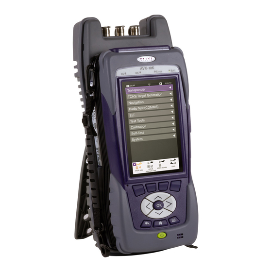
- Page 1 AVX-10K Flight Line Test Set Operations Manual...
- Page 2 A VX- 10K Fl ight Li ne Test Set Oper at io n M anual P U BL IS HE D B Y V IAV I S o lutio n s, I nc . O rigi na l Is su e A UG , 20 21 R e-is su ed (0 0 1) M AR , 20 22...
-
Page 3: Table Of Contents
Purpose and Scope ............................... 6 Product Nomenclature ............................6 Intended User ............................... 6 Related Information .............................. 7 Contact Information .............................. 7 Overview AVX-10K ..........................8 1.1. General Information ............................. 8 1.2. Principles of Operation ..........................10 Platform and System Features ........................11 1.4. - Page 4 Synchronizing to the StrataSync™ Server ..................40 2.10.5. Updating Test Set Software ....................... 43 2.10.6. Updating Software Options on AVX-10K ................... 45 Test Application Common Settings / Steps ..................47 3.1. Antenna Setups ............................47 Direct with Coupler ..........................47 3.1.1.
- Page 5 AVX-10K Operation 4.1.3. Common Test Results ........................70 4.2. ADS-B Auto ..............................71 4.2.1. Unique Setup ............................. 71 4.2.2. Run ADS-B Auto Test ......................... 72 4.3. ADS-B Monitor ............................75 4.3.1. Unique Setup ............................. 75 4.3.2. Run ADS-B Monitor ........................... 75 4.4.
- Page 6 Introduction ............................. 119 10.2. System Functions ............................. 119 11. Battery Replacement ........................121 Appendix A. AVX-10K Result Test Limits ....................126 Appendix B. Caveats and Statements ...................... 131 Caveats and Statements ............................131 Safety and Compliance Information ........................132 Symbols and Markings ............................132 Safety Definitions ..............................
-
Page 7: Table Of Figures
AVX-10K Operation Table of Figures Figure 1: AVX-10K Flight Line Operations Test Set ..................8 Figure 2: Mobile Tech Application ....................... 9 Figure 3: StrataSync™ Dashboard ........................ 9 Figure 4: Operational Test Methods ......................10 Figure 5: Front View ........................... 14 Figure 6: Side View ............................. -
Page 8: Preface
AVX-10K test set. Read this manual carefully before setting up or operating the instrument. Product Nomenclature The following terms may be used in this Operations Manual to refer to the AVX-10K Flight Line Test Set. •... -
Page 9: Related Information
Sheet: provides technical specifications. • StrataSync™ User Guide: provides operational information on the StrataSync™ Application • Contact Information Contact VIAVI Customer Service for technical support or with any questions regarding this or any other VIAVI products. Phone: 844-GO-VIAVI • email: Techsupport.avcomm@viavisolutions.com •... -
Page 10: Overview Avx-10K
1.1. General Information The AVX-10K Flight Line Test Set is a portable test instrument that provides a single instrument test solution for performing a variety of flight line testing including Transponder, TCAS, Target Generation, Navigation, Communications (COMMS), and ELT testing. -
Page 11: Figure 2: Mobile Tech Application
AVX-10K Operation Figure 2: Mobile Tech Application Figure 3: StrataSync™ Dashboard Rev. 002 2022-08-25 22135254 VIAVI Page... -
Page 12: Principles Of Operation
1.2. Principles of Operation The AVX-10K consists of the VIAVI OneExpert base platform and the AVX Application Module. The VIAVI OneExpert base platform supports system functionality such as network connectivity, system updates and power management. The AVX Application Module manages the device’s RF test and measurement functions. -
Page 13: Platform And System Features
This information is readily available on your StrataSync™ account. In the event a software update is needed, AVX-10K software can be upgraded in the field using VIAVI's StrataSync™ application (via WiFi or a direct network connection) or by downloading the latest firmware from StrataSync™... -
Page 14: First Time Use And Self-Test
AVX-10K Operation 1.6. First Time Use and Self-Test For First Time Use and unboxing instructions, please review the included Getting Started Guide. Part of the First Time Use procedure is the Self-Test process. This process should be run any time that you believe there are issues with the test set. - Page 15 External Loopback test. This cable is supplied with each AVX-10K. d. When Self-Test has completed running all tests, verify that all portions of the test have passed. If any portion of Self-Test fails, please contact VIAVI Customer Service. Turn the Test Set OFF 1.
-
Page 16: Setup, Control, And Operation
2.1. Control and Operation The AVX-10K Flight Line Test Set can be operated locally using the touchscreen, keypad or remotely using any mobile device with VIAVI's Mobile Tech application which is available at any online application store. Optionally, remote control of the AVX-10Kcan be accomplished via a VNC viewing application (such as Tight-VNC) from a laptop or PC. -
Page 17: Figure 6: Side View
AVX-10K Operation Figure 6: Side View Rev. 002 2022-08-25 22135254 VIAVI Page... -
Page 18: Controls And Buttons
AVX-10K Operation 2.2.1. Controls and Buttons The front panel controls and buttons are used to operate, control, and configure the device, change test settings, view data, and navigate the user interface (UI). • OK Button The OK Button is used to accept/confirm a changed setting or to proceed to the next menu. -
Page 19: I/O Connectors
The Function Hard Keys and UI Function Soft Keys perform the same functions. 2.2.2. I/O Connectors The AVX-10K is equipped with three TNC-type connectors on the AVX Application Module. These connectors support test and measurement functions. Figure 7: I/O Connectors Caution: Do not overload input connectors. -
Page 20: Hand Strap Rings
2.2.4. Status Indicators • TX: Transmit Indicator LED blinks green when transmitting to the device under test. RX: Receive Indicator LED blinks green when the AVX-10K is receiving input from the device • under test. • Error: This LED is solid red indicates error and alarm conditions. The type of error varies depending on the application. -
Page 21: Display Screen
2.3. Remote Operation The AVX-10K test set can be operated remotely via the Mobile Tech application or optionally via a VNC connection using a VNC application running on a computer. It is also possible to connect remotely via the Smart Access Anywhere application provided by VIAVI. -
Page 22: Mobile Tech Application
2.3.1. Mobile Tech Application VIAVI’s Mobile Tech app can be found in the Apple App Store or Google Play Store and can be run from any mobile device. This application can connect to the AVX-10K via Wireless or WIFI connection. You must have an active StrataSync™... - Page 23 WiFi and look for an SSID that starts with “VIAVI-ONX” and connect. Then in the Mobile Tech application, type in the IP for the AVX-10K at the top of the screen where it says, “Enter an IP for Manual Connection” and press the CONNECT button. The default address for the AVX-10K device is 10.0.0.1.
-
Page 24: Vnc Viewer
A VNC viewing application must be installed on the computer • AVX-10K test set and computer (both devices must be connected to the same network). • Configure the AVX-10K Remote Operation via Systems Settings using your own VNC password. This will be the password that the user of the VNC viewer software will need in order to gain access. -
Page 25: Smart Access Anywhere Application
AVX-10K Operation When you run the VNC viewer software, you will need to know the IP Address of the AVX-10K test set. This can be found by launching the Network application in the System ribbon. Figure 10: IP Address & Network ID View the Device UI Remotely 1. - Page 26 AVX-10K Operation To enable SAA on the AVX-10K and generate a code, open the System Settings application in the System ribbon, click Remote Operation, then Smart Access Anywhere and VNC. Ensure that top entry (Enable Smart Access Anywhere) is enabled and click the ‘Connect to SAA Server’ button in the lower right corner.
- Page 27 AVX-10K Operation Once connected, click the Remote Screen Page button and the application will allow you to control the test set. Once you have completed the session, click on the Session button and then ‘Disconnect”. Rev. 002 2022-08-25 22135254 VIAVI...
-
Page 28: User Interface (Ui) Layout
AVX-10K Operation 2.4. User Interface (UI) Layout This section describes the UI screen layout and UI components. 2.4.1. General Screen Layout The device’s UI area consists of a Header Bar and Main Display area. The Header Bar is system defined and appears at the top of every screen. -
Page 29: Application Screen Layout
AVX-10K Operation 2.4.3. Application Screen Layout Application screens contain the Header Bar, a main Display Area and a row of Function Soft Keys. Function Soft Keys are selected using the touchscreen or the device’s Function Hard Keys. The content of application screens varies according to the application, but layout is consistent from one application to another. -
Page 30: Ui Header Info And Indicators
AVX-10K Operation 2.5. UI Header Info and Indicators The UI uses the following indicators to show function and system status: • Active Connectivity Icons are shown at the top of the screen. When connected to the network via the LAN port, the top indicators will look like this:... - Page 31 AVX-10K Operation • AC Power Indicator The AC Power Indicator is displayed when the device is connected to an AC power supply. GPS Connection Indicator • This indicates the status of your GPS Connection: Green indicates a 3D Fix; Yellow indicates a 2D Fix, and Red indicates it is in an Acquisition state.
-
Page 32: Ui Navigation
AVX-10K Operation • Function and Test Application Status Function and test application icons change color to indicate whether or not the function is current initialized (actively running) on the device. Function Off Function icons are displayed with a white background when the function is inactive (turned off). -
Page 33: Selecting And Entering Parameters
AVX-10K Operation 2.7. Selecting and Entering Parameters The UI uses menus and editable data fields for making selections and configuring system and test parameters. Entering Alpha/Numeric Data Some parameters are defined using text or numeric entry fields (for example, test settings or user information). -
Page 34: Managing Application Shortcuts
AVX-10K Operation 2.8. Managing Application Shortcuts Figure 14: UI Shortcuts Panel The Home Screen contains an area at the bottom of the screen that can be used to create shortcuts for up to four frequently used applications. To create a shortcut Touch and hold the function icon, drag and drop the icon to the Shortcut panel located at the bottom of the screen. -
Page 35: Configuring System Settings
Configuring System Settings Figure 15: System Settings. Date and Time – Time and Date are driven by having the AVX-10K connected to an NTP • (Network Time Protocol) server. Date and Time formats can be adjusted, and Time Zone set for local time. - Page 36 • Save Location – This setting allows you to select where you want report files to be saved. They can be saved locally to the AVX-10K file folders or to a connected USB drive or to both, where applicable. Restore Factory Defaults – Resets all System and Application Settings back to factory defaults •...
-
Page 37: 2.10. Establishing Network Connections
Using an Ethernet cable, connect the instrument to the LAN: • Connect one end of the Ethernet cable to the AVX-10K Ethernet connector located on the side panel and connect the other end of the Ethernet cable to the LAN. - Page 38 AVX-10K Operation Use User Class – Enter your User Class if your network requires a User Class Use Arp Announce – If required, enable Arp Announce to have the instrument do the Arp announce after the DHCP request. Static IPv4 Address – Enter the instrument’s IP address.
-
Page 39: Establishing A Wifi Connection
AVX-10K Operation Manual – Enter the IPv6 Local Address. Automatic – The address is populated automatically. IPv6 Subnet Prefix Length – Enter the subnet prefix length. IPv6 Gateway – Enter the address for the gateway that is used to route packets that are not on the same subnet. - Page 40 6. Return to the System Network menu. The network that you created a profile for is listed on the menu. Note: Hidden SSIDs are not currently supported. To connect, un-hide the SSID, connect the AVX-10K and re-hide the SSID or leave the SSID unhidden. Rev. 002 2022-08-25...
- Page 41 AVX-10K Operation Connecting to a WiFi Connection You can manually connect to any compatible WiFi network that is within range of your instrument, and for which you have authorized access (and a password for authentication). 1. Verify that network connectivity is enabled.
-
Page 42: Establishing A Wireless Connection
2.10.4. Synchronizing to the StrataSync™ Server StrataSync™ is a hosted, cloud-based software application that provides VIAVI instruments with access to asset, configuration, and test-data management functions. StrataSync™ manages inventory, test results and performance data with browser-based ease and improves technician and instrument efficiency. - Page 43 To obtain the latest configuration settings, software options and updates, and ownership registration information, the AVX-10K can synchronize with a VIAVI server via the Internet. The synchronization also stores any user files stored on the unit to the StrataSync™ server.
- Page 44 AVX-10K Operation Server Address - Enter the DNS address for the server. The default address is: “https://stratasync.viavisolutions.com” Server Port - Enter the server port number. The default port is: 443 3. Select the Start button. As the process runs, the sync state is displayed on the screen.
-
Page 45: Updating Test Set Software
AVX-10K Operation 2.10.5. Updating Test Set Software StrataSync™ Update Procedure 1. From the StrataSync™ account, select “Update Firmware” from the Assets Menu and click the rocket ship icon next to the version of the software to install. Figure 16: StrataSync™ Update 2. - Page 46 Do not alter the filename. 4. Prepare a USB Drive as FAT32 file format. a. VIAVI Solutions advise a freshly formatted USB Drive from a reputable manufacturer, preferably with no other files on it. 5. Copy the .oxu file from step 3 to the root directory of the USB Drive.
-
Page 47: Updating Software Options On Avx-10K
2. All available software options will be displayed along with the available quantity for distribution. 3. Double-click on the option that you wish to deploy and select the AVX-10K that you wish to enable with this software option. Ensure that the serial number of the AVX-10K is the correct device. - Page 48 4. You should receive a response indicating that the software option has been deployed. Go to the StrataSync application on the AVX-10K that the software option has been deployed to and press the Start key in the lower right corner. This will enable this AVX-10K to utilize this software option.
-
Page 49: Test Application Common Settings / Steps
Direct with Coupler This is one of the more common test setup methods where the AVX-10K RF I/O port is cabled to a coupler which is then mounted over or clamped to an antenna. When using this setup, the cable loss as well as the coupler loss must be considered. - Page 50 AVX-10K Operation Three antennas are shipped with the AVX-10K-CNS kit. The larger panel antenna (AC10K-FPANT) is intended for use with all Transponder, TCAS, Target Generation and the DME Applications. The other two antennas (AC10K-ANT-ILS and AC10K-ANT-MB) are intended for use for Navigation, COMMs and ELT Testing.
-
Page 51: Direct To Uut
AVX-10K Operation 3.1.3. Direct to UUT On occasion, the AVX-10K may need to be directly connected to the UUT bypassing the antenna and cabling. When using this setup, only the cable loss will factor into the setup parameters. 3.2. Common Setup Parameters There are settings that are duplicated across many applications within the AVX-10K. -
Page 52: Rf Port
AVX-10K Operation All application-specific settings will be discussed in the associated application sections below. 3.2.1. RF Port There are three methods for any typical test setup: Direct Connect with Coupler (RF I/O), Antenna (over-the-air), and Direct Connect. The RF Port setting allows you to select the test method. -
Page 53: Antenna Settings
AVX-10K Operation 3.2.2. Antenna Settings When ANTENNA is selected as the RF Port in use, applicable settings will become active. Set Top and Bottom Antenna Range and Height in accordance with the figure below. Values can be selected by scrolling the vertical bar or using the plus and minus keys. -
Page 54: Cable Settings
AVX-10K Operation Set Antenna Gain values for 1030 MHz and 1090 MHz located on the back of the RF flat panel antenna. 3.2.3. Cable Settings The Cable Settings will be enabled when Direct Connect or Direct Connect with Coupler are selected as the RF Port setting. -
Page 55: Coupler Settings
AVX-10K Operation 3.2.4. Coupler Settings Coupler Settings will be enabled if Direct Connect with Coupler is selected as the RF Port setting. Enter the loss of the coupler being used. These values should be listed on the coupler label. 3.2.5. -
Page 56: Position Settings
USER ENTRY or VIA GPS RX. The GPS Receiver will allow you to use your local position. If needed, you can obtain your position using the GPS RX functionality of the AVX-10K. GPS Position Format can be set to be displayed in Degrees, Degrees Minutes, or Degrees Minutes Seconds. -
Page 57: Advanced Settings
Verify Unit Setup Configuration – when set to YES, this will cause a pop-up screen to appear after the RUN button is selected, allowing the user to verify the AVX-10K is set up correctly prior to running the test. Setting this to NO will disable this popup screen. -
Page 58: Recall Data Button
AVX-10K Operation 3.2.8. Recall Data Button At the bottom of most SETUP screens is a “Recall Data” button. Pressing this button will bring up a list of Previously Saved Tests. You can select any of these tests and then press the LOAD key and the main screen of the associated instrument will populate the fields and display the data in the state that it was displayed when the SAVE was performed. - Page 59 AVX-10K Operation Note: Overall Test Status and Ribbon Title may show “NOT RUN”, but all of the fields below will be populated. Rev. 002 2022-08-25 22135254 VIAVI Page...
-
Page 60: Managing Files / Reports Via Usb And Stratasync
AVX-10K Operation 3.3. Managing Files / Reports via USB and StrataSync™ 3.3.1. Saving Reports After running a test or collecting monitored information, press SAVE to access the Save Test screen. The Test Name can be overwritten or used as provided and saved locally by selecting the Save button. -
Page 61: File Management
AVX-10K Operation 3.3.2. File Management The AVX-10K file browser is used to open, rename, copy, or delete saved test result files, screen shots, or other files stored on the device. Open the File Browser Expand the System ribbon and select the File Browser icon. - Page 62 AVX-10K Operation Use the up and down arrow keys to navigate folders or files. Rev. 002 2022-08-25 22135254 VIAVI Page...
- Page 63 AVX-10K Operation Opening a File or Folder You can open a folder using any of the following: Check the box next to the folder and select Open at the bottom of the page • Tap anywhere on the folder field you wish to open •...
- Page 64 AVX-10K Operation Once opened, a list of test results are shown in TXT, HTML and .json formats. Rev. 002 2022-08-25 22135254 VIAVI Page...
- Page 65 AVX-10K Operation TXT and .json formats can be exported and formatted by users for report generation in supporting programs. HTML format is readable on the device as shown below and as a downloaded file / test report. Note – in the tray there is a View Reports icon where all HTML reports can also easily be viewed on the device.
- Page 66 AVX-10K Operation Copy Files or Folders 1. Open the File Browser. 2. Select a file or folders. Multiple folders can be selected for download by checking the box next to the folder (for example, to copy multiple files to USB, or upload multiple files using FTP/ HTTP).
-
Page 67: Transponder
AVX-10K Operation Transponder 4.1. XPDR Auto 4.1.1. Unique Setup Refer to Chapter 3 for common setup items. Setting Definition Diversity (on, off) Set to ‘On’ to test both top and bottom antennas for a diversity system and Diversity Isolation Test... -
Page 68: Run Transponder Auto Test
AVX-10K Operation Setting Definition Advanced – RAD47 An Australian directive for civil aviation where the reply pulse width is between 0.35 to 0.55 us and amplitude variation (droop) is not greater than 1dB. Set to ON if applicable. 4.1.2. Run Transponder Auto Test With the Transponder AUTO TEST ribbon expanded, you will see that the Test Configuration Box is shaded identifying it as an active field. - Page 69 AVX-10K Operation Configuration Description GENERIC MODE S Tests Mode S transponders, specifically when the class of the transponder is unknown plus this test includes test requirements like EHS/ELS in addition to the FAR Part 43 Appendix F test. GENERIC ATCRBS Tests ATCRBS transponders, specifically when the class of the transponder is unknown.
- Page 70 AVX-10K Operation If any of the tests fail, you can open the associated ribbon to see the resultant failure. If any of the individual test ribbons are expanded and the Run button is selected, you will be asked if you want to loop on that specific expanded ribbon test, which will also include all expanded ribbons, or run a complete test.
-
Page 71: Run Encoder Test
For transponder configured fields, the AVX-10K only displays the decoded data and cannot determine PASS/FAIL criteria for these fields. Note: In the test results, the nomenclature ITM refers to “Intermode”. Intermode is when a Mode A or C Interrogation is tested along with a Mode S Interrogation. -
Page 72: Common Test Results
AVX-10K Operation screen ensure that the Encoder Test On softkey is in the ON position. This setting will provide a faster interrogation rate to display the MODE C Altitude. 4.1.3. Common Test Results Test Status Indication Description NOT RUN RUN button has not yet been pressed NO REPLY UUT has not yet provided the information. -
Page 73: Ads-B Auto
AVX-10K Operation 4.2. ADS-B Auto 4.2.1. Unique Setup Refer to Chapter 3 for common setup items. Rev. 002 2022-08-25 22135254 VIAVI Page... -
Page 74: Run Ads-B Auto Test
AVX-10K Operation Setting Definition Barometric Altitude Set to ‘YES’ and enter test altitude for comparison to transponder Reference reported barometric altitude Test Type Allows selection between AC20-165 FAA Advisory Circular for testing ADS-B installed systems and CS-ACNS applicable EASA requirements Test Type >... - Page 75 AVX-10K Operation Once the Airborne tests have completed, move to the Surface screen, set the aircraft under test in the surface mode (weight on wheels) and select the Run button. Rev. 002 2022-08-25 22135254 VIAVI Page...
- Page 76 AVX-10K Operation Once the testing completes successfully, the screens will look similar to this: Note: If the HEADING field is displayed in yellow (typical), this is because the aircraft is stationary. If you choose to save your test results, please refer to Chapter 3 for managing reports.
-
Page 77: Ads-B Monitor
AVX-10K Operation 4.3. ADS-B Monitor The AVX-10K provides flight line test capability for receiving (ADS-B Monitor mode), decoding and displaying full ADS-B DO-260/A/B DF17/DF18 extended squitter transmissions from Mode S transponders or DF18 extended squitters from 1090 MHz emitters. 4.3.1. - Page 78 AVX-10K Operation When running this test, the returned values can include: INTERVAL TIME (squitter has been captured) • NO SQUITTER (squitter not captured) • • NO REPLY (no squitter was received) NOT RUN (test has not yet been run) •...
-
Page 79: Gicb
AVX-10K Operation 4.4. GICB GICB mode fully decodes and displays all Enhanced Surveillance BDS register contents. 4.4.1. Unique Setup Refer to Chapter 3 for common setup items. Setting Definition Advance – GICB Choose DF20 or DF21. Typically left as DF20. This option is available Downlink Format for change due to the transponder specification. -
Page 80: Gibc Monitoring
AVX-10K Operation 4.4.2. GIBC Monitoring The default mode (Simple Mode) will query for common GICB register values. Toggle the mode by pressing the Simple Mode key and the test set will query for all GICB registers (Adv. Mode). If you choose to save your results, please refer to Chapter 3 for managing and viewing reports. -
Page 81: Uat Monitoring
AVX-10K Operation 4.5. UAT Monitoring 4.5.1. Unique Setup Refer to Chapter 3 for common setup items. For the UAT Monitor application, there are no unique settings in the SETUP tab. 4.5.2. Run UAT Monitoring Press the RUN button to start received and decoding UAT Out information. Each unique payload will be displayed on separate lines under the Aircraft List tab. - Page 82 AVX-10K Operation Press the Next Payload softkey at the bottom of the screen to display details for each payload. Any decoded information received from the UUT will be displayed in the associated tabs as shown here. Rev. 002 2022-08-25 22135254...
- Page 83 AVX-10K Operation Press the Save Data button to capture and store the received information. Rev. 002 2022-08-25 22135254 VIAVI Page...
-
Page 84: Tcas / Target Generation
AVX-10K Operation TCAS / Target Generation 5.1. TCAS 5.1.1. Unique Setup Refer to Chapter 3 for common setup items. The following unique setup parameters are found on the SETUP tab for the TCAS application. Setting Description Test Set Address Enter a 6-digit Hexadecimal address other than the address of the unit under test. -
Page 85: Run Tcas Scenario
AVX-10K Operation The main screen of the TCAS application also has a number of configurable parameters. These configurable fields have a blue background. Setting Description Scenario Allows for selection of predefined scenarios and a provision for saving custom scenarios. When one of the predefined scenarios are selected, all the following parameters will be loaded with values. - Page 86 AVX-10K Operation Rev. 002 2022-08-25 22135254 VIAVI Page...
- Page 87 AVX-10K Operation Press the RUN button to start generating the scenario. While running the fields with the white background shown here will be updating and will turn to a green background. You can click on the tabs or swipe right to view the additional data.
- Page 88 AVX-10K Operation Rev. 002 2022-08-25 22135254 VIAVI Page...
- Page 89 AVX-10K Operation If you created a new profile, you may choose to save for later use by pressing the Save Profile button, selecting one of the custom fields and then pressing the Save Scenario button. Rev. 002 2022-08-25 22135254 VIAVI...
-
Page 90: Target Gen
AVX-10K Operation 5.2. Target Gen 5.2.1. Unique Setup Refer to Chapter 3 for common setup items. For the Target Generation application, there are no unique settings in the SETUP tab, however, the main screen of the TARGET GEN application has a number of configurable parameters. -
Page 91: Run Target Gen
AVX-10K Operation Altitude Enter a value between -3500 and 3500 feet to define the vertical distance from the UUT. Altitude Rate Select between CLIMB, LEVEL, DESCEND 5.2.2. Run Target Gen This application will allow you to set up to five static intruders for testing of ADS-B In Receivers. Any of the fields with a blue background are editable. -
Page 92: Uat Gen
AVX-10K Operation You may choose to save for later use by pressing the Save/Recall Configuration button, selecting one of the custom fields and then pressing the Save Configuration button. 5.3. UAT GEN 5.3.1. Unique Setup Refer to Chapter 3 for common setup items. For the UAT Traffic Generation application, there are no unique settings in the SETUP tab, however, the main screen of the UAT GEN application has a number of configurable parameters. - Page 93 AVX-10K Operation Aircraft Under Test Description Setting Target Type Select between ADS-B and TIS-B AG State Toggles between AIRBORNE and GROUND Latitude Set to Latitude of UUT Longitude Set to Longitude of UUT Heading Enter a value between 0 and 359 degrees...
- Page 94 AVX-10K Operation The configurable settings for the FIS-B data (click on the FIS-B tab to view, setup and run) include: FIS-B Weather Description Report Select between METAR and TAF (the predefined settings will be displayed in the Weather Data section at the bottom of the screen).
-
Page 95: 5.3.2. Run Uat Gen
AVX-10K Operation 5.3.2. Run UAT Gen This application will allow you to set up to five static intruders for testing of UAT-In Receivers. The UAT Gen application is dependent on precise timing parameters. Should this screen popup, it is a notification that the unit is likely past the calibration schedule. - Page 96 AVX-10K Operation FIS-B information can also be sent using this application by selecting the FIS-B tab, setting up the configurable parameters as defined above and then pressing the RUN button. Rev. 002 2022-08-25 22135254 VIAVI Page...
-
Page 97: Navigation
AVX-10K Operation Navigation 6.1. Integrated Landing System (ILS) Operation 6.1.1. Setup The settings for the ILS application are described in the table below. Setting Definition RF Port The ILS Instrument supports either over-the-air antenna testing or direct connection to the LRU. - Page 98 AVX-10K Operation This parameter allows for compensation (0.0 to 22.0 dB) of an External Attenuation External Attenuator on the RF I/O Connector. This is used for extending the power monitor rating and range. If the External Attenuator is selected, the value is displayed on all Mode Screens in the EXT ATTN Field under the RF LVL Field.
-
Page 99: 6.1.2. Run Ils Application
AVX-10K Operation 6.1.2. Run ILS Application Once you enter the ILS Application, the ILS Instrument is running. Changes to the Instrument Setup can be made at any time. The instruments supported by the ILS Application include: Setting Definition ILS Tri Mode... - Page 100 AVX-10K Operation Glide Slope Only Marker Beacon Only All Instruments Off When turning Localizer, Glideslope, and Marker Beacon functions on and off, a “SELECT VALID MODE” popup might appear that helps to drive you to one of these available modes.
- Page 101 AVX-10K Operation Setting Definition LOC Button Settings include OFF, ON, TONE, and MORSE GS Button Can be set to ON or OFF MKR Button Can be set to OFF, OUTER 400 Hz, MIDDLE 1300 Hz, or INNER 3000 Hz Can also be selected by clicking on the “O”, “M” and “I” indicators.
- Page 102 AVX-10K Operation Setting Definition When set to CHANNEL, the UP/DOWN Arrow keys will cycle through the list of valid channels. This list can be seen by clicking in the center of the control and the channel can be directly selected in this manner.
-
Page 103: Vhf Omnidirectional Ranging (Vor) Operation
AVX-10K Operation Save Settings button: This allows all of the values on the main page to be saved for later recall as needed. Center Deviation button: This sets the LOC and G/S offsets to zero. 6.2. VHF Omnidirectional Ranging (VOR) Operation 6.2.1. -
Page 104: 6.2.2. Run Vor Application
AVX-10K Operation Setting Definition RF Port The VOR Instrument supports either over-the-air antenna testing or direct connection to the LRU. RF Power Units Can be set to dBm or V (Volts in 50 ohms) PRESET, CHANNEL OR VAR: Frequency Input Type PRESET provides a set of three fixed frequencies;... - Page 105 AVX-10K Operation Setting Definition TO / FROM Press to toggle between TO and FROM. TO sets the Bearing towards the VOR Beacon and FROM set the Bearing away from the VOR Beacon. Toggles BEARING control between FIXED and VARIABLE. FIXED allows settings from BEARING STEP 0 to 330 in 30-degree steps.
-
Page 106: Distance Measuring Equipment (Dme)
AVX-10K Operation This field depends on the setting of BEARING STEP. If BEARING STEP is FIXED, the BEARING UP/DOWN Arrow keys will update the value in 30-degree increments. Clicking in the center of the control will allow direct selection of a Bearing value from 0 to 330 degrees. - Page 107 AVX-10K Operation Setting Definition Frequency Entry Allows selection of either Presets or Manual entry of Frequencies. Type Identification Code Enter the three characters that will be used for Morse code ident. Squitter Sets squitter output to ON or OFF Maximum Range...
-
Page 108: 6.3.2. Run Dme Application
AVX-10K Operation Setting Definition Preset (MHz) Will toggle between 108.05, 117.95 and 108.00. The paired TX Frequency, Channel and Mode values will change accordingly. VOR (MHz) When in Manual Frequency Entry mode, allows setting a value between 108.00 and 135.05. The paired TX Frequency, Channel and Mode will change accordingly. - Page 109 AVX-10K Operation Rev. 002 2022-08-25 22135254 VIAVI Page...
-
Page 110: Radio Test (Comms)
AVX-10K Operation Radio Test (COMMS) 7.1. VHF COM Amplitude Modulation (AM) (Reserved) 7.2. VHF COM Frequency Modulation (FM) (Reserved) 7.3. COM High Frequency (HF) Single Side Band (SSB) (Reserved) 7.4. COM SelCal (Reserved) Rev. 002 2022-08-25 22135254 VIAVI Page... -
Page 111: Elt
AVX-10K Operation 8.1. ELT 121.5 (Reserved) 8.2. ELT 243 (Reserved) 8.3. ELT 406 (Reserved) Rev. 002 2022-08-25 22135254 VIAVI Page... -
Page 112: Test Tools
AVX-10K Operation Test Tools 9.1. VSWR 9.1.1. VSWR Test Function The VSWR test function provides users with the ability to troubleshoot potential cabling and / or antenna issues. Voltage Standing Wave Ratio (VSWR) is a measurement that represents how well an antenna's •... -
Page 113: Equipment Needed For Vswr Test
• Cable or antenna to be tested • Calibration Kit (short cable with short and load – included with the AVX-10K) Run VSWR Calibration 1. It is recommended that the VSWR calibration be performed prior to testing any antenna or cable. - Page 114 AVX-10K Operation 3. Power on the AVX-10K. 4. Select the Test Tools ribbon on the Home screen. 5. Select the VSWR/DTF application. 6. Select the VSWR tab. 7. Press the Calibrate soft-key. 8. Select External Standards. Select OK button to confirm.
- Page 115 AVX-10K Operation 10. When external calibration has been completed, the calibration plot should resemble the following figure. Rev. 002 2022-08-25 22135254 VIAVI Page...
-
Page 116: Figure 19: Vswr Test Setup Diagram
AVX-10K Operation Perform VSWR Test Figure 19: VSWR Test Setup Diagram Configure the AVX-10K for VSWR Test 1. Power on the AVX-10K. 2. Select the Test Tools ribbon on the Home screen. 3. Select the VSWR/DTF application. 4. Select the VSWR tab. -
Page 117: Distance To Fault
AVX-10K Operation Review Test Data 1. Observe the VSWR trace. 2. This example shows an antenna that appears to be tuned well for 1030 MHz and 1090 MHz which indicates a good antenna. A poor antenna would have high VSWR values in this band. -
Page 118: Scope Of Dft Test
Equipment Needed for DTF Test The following equipment is required to perform the procedures defined in this section: Cable to be tested • TNC adapter if applicable to interface with the AVX-10K SWR port • Perform DTF Test Figure 20: DTF Test Setup Diagram Configure the AVX-10K for DTF Test 1. - Page 119 8. Open the instrument settings menu and set the stop distance to a distance longer than the cable under test. 9. Close the instrument settings tab and ensure the DTF enable soft key displays DTF on. The AVX-10K will display the DTF trace. Rev. 002 2022-08-25...
- Page 120 AVX-10K Operation 11. Set the marker to the peak which reflects a fault indication to determine the distance to fault. The markers can be moved manually or using the peak buttons at the bottom of the screen. The middle button is peak find and the adjacent buttons are next peak left or right (if additional peaks exist).
-
Page 121: 10. System And Utility Functions
AVX-10K Operation 10. System and Utility Functions 10.1. Introduction System and utility functions configure device parameters such as date and time, network, WiFi and Wireless access. The Test Set contains built-in signal generators and modulators for XPDR frequencies. System and utility functions also support file management, user setup information and updating the device’s software and firmware. - Page 122 AVX-10K Operation StrataSync™ – This application allows for reports to be pushed to the StrataSync™ server. It is • recommended that synchronization be performed often to check for firmware updates. Network – You can select between WIFI or hard-wired connectivity and set all of the associated •...
-
Page 123: 11. Battery Replacement
AVX-10K Operation 11. Battery Replacement Caution: Remove device from AC power supply. To Remove the Battery. Place the test set on a suitable work bench with the display facing down. Loosen but do not fully remove the six flat blade, captive screws that secure the module to the base unit. - Page 124 AVX-10K Operation Caution: Remove cover carefully to avoid damaging the PCB assembly and water seal. If module sticks to the base unit, insert a screwdriver where pry slots are provided and gently pry until module releases. Disconnect the module from the base unit while carefully avoiding damage to the PCB assembly.
- Page 125 AVX-10K Operation Loosen the screw that secures the battery cover and remove the cover to expose the battery. Push tab on battery cable connector clip to release and pull cable away from connector. Rev. 002 2022-08-25 22135254 VIAVI Page...
- Page 126 AVX-10K Operation Remove battery from the device. Dispose of the old battery according to local regulations. Rev. 002 2022-08-25 22135254 VIAVI Page...
- Page 127 AVX-10K Operation New Battery Installation Procedure WARNING: The battery that came with the device is a Lithium-Ion battery. If the battery is not installed correctly it may explode. Use care when installing the battery to ensure the battery is properly inserted in the device.
-
Page 128: Appendix A. Avx-10K Result Test Limits
AVX-10K Operation Appendix A. AVX-10K Result Test Limits List of explanations for all tests. Field name Test performed Autotest summary ribbon Level Level of the transponder being reported by the transponder being tested No FAR reference A code Mode A code being reported... - Page 129 AVX-10K Operation Field name Test performed A/C Decoder/SLS ribbon SLS A Code 0dB Replies <1% when P2 is equal in amplitude to P1. FAR 43 Appendix F paragraph (b) -9dB Replies >90% when P2 is -9dB down from P1 FAR 43 Appendix F paragraph (b)
- Page 130 Time period between DF11 acquisition squitters FAR 43 Appendix F paragraph (j) Diversity Isolation If turned on the AVX-10K will determine if the Isolation between the top and bottom channels is within tolerance. Disabled by the operator if not a diversity transponder.
- Page 131 AVX-10K Operation Field name Test performed FAR 43 Appendix F paragraph € UF4 ribbon Was the reply to this interrogation a DF4 FAR 43 Appendix F paragraph (g) Displays the Altitude Code in the DF4 FAR 43 Appendix F paragraph (g)
- Page 132 AVX-10K Operation Field name Test performed Mode C ALT Compare Compares the altitude from the Mode C reply to the altitude in the reply from the UF20 FAR 43 Appendix F paragraph (h) DF11 Address Compare Compares the address from the DF11 squitter to the...
-
Page 133: Appendix B. Caveats And Statements
Copyright/Trademarks • © Copyright 2022 VIAVI Solutions Inc. All rights reserved. No part of this guide may be reproduced or transmitted, electronically or otherwise, without written permission of the publisher. VIAVI Solutions and the VIAVI logo are trademarks of VIAVI Solutions Inc. (“VIAVI”). All other trademarks and registered trademarks are the property of their respective owners. -
Page 134: Safety And Compliance Information
• Open Source Disclaimer - IMPORTANT READ CAREFULLY The AVX-10K Flight Line Test Set includes third party software licensed under the terms of separate open source software licenses. By using this software you agree to comply with the terms and conditions of the applicable open source software licenses. Software originated by VIAVI is not subject to third party licenses. - Page 135 AVX-10K Operation ESD Sensitive Indicates item is static sensitive. Item should only be handled by Qualified Service Personnel. Voltage Symbol This symbol represents hazardous voltages. It may be associated with either a DANGER, WARNING, CAUTION, or ALERT message. Hot Surface Symbol This symbol represents a risk of a hot surface.
- Page 136 AVX-10K Operation GITEKI Certification (Japan) 当該機器には電波法に基づく、技術基準適合証明等を受けた特定無線 設備を装着している。 電波法により5.2/5.3 GHz帯は屋内使用に限ります The Giteki certification includes two types namely Technical Standards Conformity Certification and Construction Design (Construction Type) Certification. Technical Standards Conformity Certification • Certify and test for conformity of an equipment for each unit to which the certification mark “Giteki”...
-
Page 137: Safety Definitions
AVX-10K Operation Safety Definitions This Operation Manual uses the following terms to indicate conditions or activities which are potential safety hazards: Term Definition Identifies conditions or activities that, if ignored, can result in WARNING personal injury or death. Caution Identifies conditions or activities that, if ignored, can result in equipment or property damage, e.g., Fire. -
Page 138: Electrical Hazards
AVX-10K Operation • Electrical Hazards WARNING: Improper grounding of equipment can result in electrical shock. To ensure proper grounding, this device should only be connected to a grounded AC Power Supply. The instrument is provided with a protective grounding lead that conforms with IEC Safety Class I. - Page 139 (see section “Electromagnetic Interference (EMI)” on page xii). The authority to operate this product is conditioned by the requirements that no modifications be made to the equipment unless the changes or modifications are expressly approved by VIAVI. • Industry Canada Requirements This Class A digital apparatus complies with Canadian ICES-003.
- Page 140 Electronic Equipment (WEEE) Directive, 2012/19/EU, and the EU Battery Directive, 2006/66/EC. Information and instructions for returning waste equipment and batteries to VIAVI can be found on the VIAV website in the WEEE section of the VIAVI Standards and Policies web page at: https://www.viavisolutions.com/en-us/corporate/legal/policies-standards#sustain.
-
Page 141: Appendix C. Safety Data Sheets
AVX-10K Operation Appendix C. Safety Data Sheets Safety Data Sheets • Rechargeable Lithium-Ion Batteries Rev. 002 2022-08-25 22135254 VIAVI Page... - Page 142 Other materials, such as the battery housing and the electrical insulation, are not hazardous under normal conditions but may emit hazardous chemicals such as carbon dioxide, carbon monoxide and formaldehyde in a fire. VIAVI Solutions Document 22055514 Revision 010 effective 1 Jan 2022...
- Page 143 Store in a dry place, at temperatures between -40C (-40F) and 60C (140F). Exposure to extreme high temperatures can cause the cells within the battery to vent (releasing chemicals that might become hazardous). VIAVI Solutions Document 22055514 Revision 010 effective 1 Jan 2022...
- Page 144 Ecological damage has not occurred and is not expected to occur under normal conditions. Keep away from open flame, hot surfaces, and sources of ignition. Do not puncture, crush or incinerate cells. Do not flush into surface water or sanitary sewer system. VIAVI Solutions Document 22055514 Revision 010 effective 1 Jan 2022...
- Page 145 Transport information For transportation purposes, lithium ion batteries are considered dangerous goods. All lithium ion batteries used in all active VIAVI Solutions products comply with requirements defined by ICAO, IMDG, US DOT, ADR, UN Model Regulations, and IATA DGR (63 Edition, 2022).
- Page 146 Consult your shipping company or freight forwarder ahead of time. Regulatory information All lithium ion batteries sold by VIAVI Solutions have been tested and found to comply with the requirements of the UN Manual of Tests and Criteria, Section 38.3.
- Page 147 22135254 / Rev. 002 Part of CD: 22141759 August 2022 English VIAVI Solutions North America: 1.844.GO VIAVI / 1.844.468.4284 Latin America +52 55 5543 6644 EMEA +49 7121 862273 APAC +1 512 201 6534 All Other Regions: viavisolutions.com/contacts...
Need help?
Do you have a question about the AVX-10K and is the answer not in the manual?
Questions and answers