
Subscribe to Our Youtube Channel
Related Manuals for ADLINK Technology IMB-M47


Summary of Contents for ADLINK Technology IMB-M47
- Page 1 IMB-M47 User’s Manual ATX Motherboard with 12/13th Gen Intel ® Core™ i9/i7/i5/i3 Processors and Intel Q670 Chipset ® Manual Rev.: Revision Date: Sep.20, 2023 Part Number: 50M-13016-1000...
- Page 2 Preface Copyright Copyright 2022 ADLINK Technology, Inc. This document contains proprietary information protected by copyright. All rights are reserved. No part of this manual may be reproduced by any mechanical, electronic, or other means in any form without prior written permission of the manufacturer.
- Page 3 IMB-M47 Revision History Revision Description Date Initial release 2023-09-20 Preface...
-
Page 4: Table Of Contents
Table of Contents Preface ..........................ii Table of Contents ......................iv List of Figures ........................vi List of Tables ........................vii Introduction ........................ 1 Packing List ........................ 1 Optional Accessories ....................1 Specifications ......................3 Core System ....................... 3 I/O Interface ........................ 4 Video ........................... -
Page 5: Preface
IMB-M47 Security Screen ......................50 Boot Screen ......................54 Exit Screen ....................... 55 Safety Instructions ......................57 Getting Service ......................... 58 Preface... -
Page 6: List Of Figures
List of Figures Figure 1: Functional Block Diagram ......................6 Figure 2: IO Panel Connector Locations ....................7 Figure 3: Onboard Connector Locations ....................8 Figure 4: Mechanical Dimensions ......................11 Figure 5: Mechanical Dimensions - IO Panel ..................12 Preface... -
Page 7: List Of Tables
IMB-M47 List of Tables Table 1: IO Panel Connector Definitions ....................7 Table 2: Onboard Connector Definitions ....................9 Preface... - Page 8 This page intentionally left blank. viii Preface...
-
Page 9: Introduction
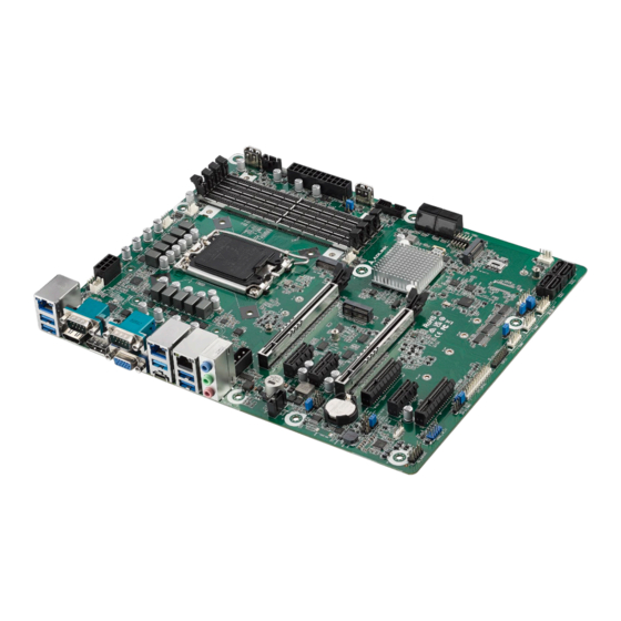
IMB-M47 1 Introduction ADLINK IMB-M47 ATX is an industrial motherboard supporting 12/13th Generation Intel® Core™ i9/i7/i5/i3 desktop processors, an Intel® Q670 Chipset, and 7 PCIe expansion slots to provide a cost-competitive embedded computing solution. It includes high-speed data transfer interfaces such as PCIe 5.0, USB 3.2 Gen2, and SATA 6 Gb/s (SATA III), and dual-channel DDR5 3600/4000/4800 MHz RAM for industrial automation applications. - Page 10 This page intentionally left blank. Introduction...
-
Page 11: Specifications
IMB-M47 2 Specifications Core System CPU: Intel® Core™ i9-12900E, 5.00GHz, 16 Core, DDR5 4800MHz supported, 30M Cache, 65W TDP • Intel® Core™ i9-12900TE, 4.80GHz, 16 Core, DDR5 4800MHz supported, 30M Cache, 35W TDP • Intel® Core™ i7-12700E, 4.80GHz, 12 Core, DDR5 4800MHz supported, 25M Cache, 65W TDP •... -
Page 12: I/O Interface
I/O Interface Expansion slots: • 1x PCIe x16 Gen5 • 1x PCIe x8 Gen5 2x PCIe x4 Gen4 • 3x PCIe x1 Gen3 • SATA: 8x SATA 6.0 Gb/s connectors, Intel® software RAID 0/1/5/10 support USB: 1x USB 3.2 Gen2 type C connector (rear) •... -
Page 13: Temperatures
IMB-M47 Temperatures Operating Temperature: 0°C to 60°C Storage Temperature: -40°C to 85°C Humidity 60°C at 90% RH, non-condensing Certificate (EMC) CE/FCC Class B Form Factor ATX: 305 mm x 244 mm (W x L) 2.10 Operating Systems Microsoft®... -
Page 14: Functional Block Diagram
2.11 Functional Block Diagram Figure 1: Functional Block Diagram Specifications... -
Page 15: Mechanical Layout
IMB-M47 3 Mechanical Layout Connector Locations Figure 2: IO Panel Connector Locations Table 1: IO Panel Connector Definitions IO Panel Connectors Item Description USB 3.2 Gen2 Port USB 3.2 Gen2 Port RJ45 LAN Port (LAN3) COM Port (COM1) (RS232/422/485) COM Port (COM2) (RS232/422/485) -
Page 16: Figure 3: Onboard Connector Locations
PCIE1 PCIE2 PCIE3 PCIE4 CMOS Battery PCIE5 PCIE6 PCIE7 Figure 3: Onboard Connector Locations Mechanical Layout... - Page 17 IMB-M47 Table 2: Onboard Connector Definitions Onboard Connectors Item Description Remarks COM Port Pin9 PWR Setting Jumpers PWR_COM1~2 (For COM Port1~2) PS/2 Keyboard/Mouse Header LAN LED Headers I225_LED3 (For LAN3 Port) ATX 12V Power Connector ATX12V1 Chassis Fan Connectors (+12V)
- Page 18 Onboard Connectors Buzzer BUZZ2 Clear CMOS Headers CLRMOS1~2 PWR_BAT1 LAN LED Headers (For LAN1~2 Port) I225_LED1 I225_LED2 DACC1 M.2 Key-E Socket M2_E1 5-pin Thunderbolt AIC Connector PCIe Power Connector PCIE_PWR1 Mechanical Layout...
-
Page 19: Mechanical Dimensions
IMB-M47 Mechanical Dimensions Top View Dimensions: mm Figure 4: Mechanical Dimensions Mechanical Layout... -
Page 20: Figure 5: Mechanical Dimensions - Io Panel
Side View Dimensions: mm Figure 5: Mechanical Dimensions - IO Panel Mechanical Layout... -
Page 21: Connector Pinouts
IMB-M47 4 Connector Pinouts See 3.1 Connector Locations on page 7 for connector locations. Rear IO Connectors 4.1.1 HDMI Signal Signal HDMI1_CON_DP2 HDMI1_CON_DN2 HDMI1_CON_DP1 HDMI1_CON_DN1 HDMI1_CON_DP0 HDMI1_CON_DN0 HDMI1_CON_CKP HDMI1_CON_CKN HDMI1_DDC_CLK HDMI1_DDC_DATA +5V_HDMI HDMI1_CON_HPD 4.1.2 DisplayPort Signal Signal CN_DDPx0+ CN_DDPx0- CN_DDPx1+... - Page 22 4.1.3 VGA Connector Signal Signal VGA_CON_RED VGA_CON_GREEN VGA_CON_BLUE +5V_HDMI VGA_DDCDAT VGA_CON_HS VGA_CON_VS VGA_DDCCLK 4.1.4 COM 1-2 Connectors COM1 and COM2 ports (RS232/422/485) can be adjusted in BIOS setup utility > Advanced Screen > Super IO Configuration. Signal RS-232 RS-422 RS-485 DCD# Tx/Rx- Tx/Rx+...
- Page 23 IMB-M47 4.1.5 Ethernet Connectors (LAN1, LAN2, LAN3) Three 10/100/1000/2500 Mbps LAN Ethernet controllers based on Intel® i226LM, support PXE and WOL. LAN2 supports vPro. 10BASE-T/100BASE-TX 1000BASE-T LAN_MDI0+ LAN_MDI0- LAN_MDI1+ LAN_MDI2+ LAN_MDI2- LAN_MDI1- LAN_MDI3+ LAN_MDI3- LED1 (Speed) LED2 (Link/Activity) Status Description...
-
Page 24: Onboard Headers / Connectors
Onboard Headers / Connectors 4.2.1 PS/2 Keyboard/Mouse Header Signal Signal Signal Signal KBCLK KBDATA MSDATA MSCLK 4.2.2 LAN LED Header Signal Signal Signal Signal LILEDP LED_LNK#_ACT LED_1000# LED_2500# 4.2.3 ATX12V Power Connector This motherboard provides an 8-pin ATX 12V power connector. To use a 4-pin ATX power supply, please plug it along Pin 1 and Pin 5. - Page 25 IMB-M47 4.2.6 USB 2.0 Connectors There are two USB 2.0 Type-A vertical connectors on this motherboard. Signal USB_D+ USB_D- USB_PWR 4.2.7 PSU_SMB1 Signal SMB_CLK SMB_DATA SMBALERT# 4.2.8 24-pin ATX Power Input Connector This motherboard provides a 24-pin ATX power connector. To use a 20-pin ATX power supply, plug it along Pin 1 and Pin 13.
- Page 26 4.2.9 USB 3.2 Gen 1 Header 4.2.10 SATA3 Connectors The Serial ATA3 (SATA3) connectors support SATA data cables for internal storage devices. The current SATA3 interface allows up to 6.0 Gb/s data transfer rate. Signal Signal SATA-B- SATA-A+ SATA-B+ SATA-A- 4.2.11 System Panel Header This header accommodates several system front panel functions.
- Page 27 IMB-M47 4.2.13 ESP1 Header (ESP1) ESPI_CLK ESPI_CS# SMB_CLK_MAIN ESPI_RST# SMB_DATA_MAIN ESPI_IO3 ESPI_IO2 ESPI_IO1 ESPI_IO0 +3VSB ESPI_ALERT# 4.2.14 Printer Port / GPIO Header If you want to use the printer port function, please short pin4 and pin5 on Digital Input / Output Power Select (JGPIO_PWR1).
- Page 28 4.2.15 USB 2.0 Header USB PWR DUMMY USB PWR 4.2.16 SPDIF Header SPDIF header, providing SPDIF audio output to HDMI VGA card, allows the system to connect HDMI Digital TV/projector/LCD devices. Please connect the SPDIF connector of HDMI VGA card to this header. 4.2.17 Front Panel Audio Header This is an interface for front panel audio cable that allows convenient connection and control of audio devices.
- Page 29 IMB-M47 4.2.20 5-pin Thunderbolt AIC Connector Pin Signal TB_FRC_PWR TBCIO_PLUG_EVENT_R2 SLP_S3 TBT_SLP_S5_S4# 4.2.21 PCIe Power connector +12V Connector Pinouts...
-
Page 30: Jumper And Swtich Settings
Jumper and Swtich Settings 4.3.1 COM Port Pin9 PWR Setting Jumpers (No.1, 2, 25) 3-pin PWR for COM Port 1, COM Port 2, and COM Port 3~6. 1-2: +5V 2-3: +12V 4.3.2 Chassis Intrusion Headers (No. 10, 13) This motherboard supports CASE OPEN detection feature that detects if the chassis cover has been removed. This feature requires a chassis with chassis intrusion detection design. -
Page 31: Expansion Slots
IMB-M47 4.3.7 Clear CMOS Jumpers (No. 35) CLRMOS1 allows you to clear the data in CMOS. To clear and reset the system parameters to default setup, please turn off the computer and unplug the power cord from the power supply. After waiting for 15 seconds, use a jumper cap to short pin2 and pin3 on CLRMOS1 for 5 seconds. - Page 32 M.2 sockets: M.2 Key-M (M2_M1) • Signal Signal +3.3V +3.3V PERn3 PERp3 PETn3 +3.3V PETp3 +3.3V +3.3V PERn2 +3.3V PERp2 PETn2 PETp2 PERn1 PERp1 PETn1 PETp1 DEVSLP SMB_CLK PERn0 SMB_DATA PERp0 PETn0 PETp0 PERST# CLKREQ# PEFCLKn WAKE# PEFCLKp PEDET +3.3V +3.3V +3.3V Connector Pinouts...
- Page 33 IMB-M47 M.2 Key-E (M2_E1) • Signal Signal +3VSB USB_D+ +3VSB USB_D- CNV_WGR_D1- CNV_RF_RESET CNV_WGR_D1+ MODEM_CLKREQ CNV_WGR_D0- CNV_WGR_D0+ CNV_WGR_CLK- CNV_BRI_RSP CNV_WGR_CLK+ CNV_BGI_DT PETp CNV_RGI_RSP PETn CNV_BRI_DT PERp PERn PEFCLKp PEFCLKn SUSCLK CLKREQ# PERST0# WAKE# W_DISABLE1# W_DISABLE2# CNV_WT_D1- SMB_DATA CNV_WT_D1+ SMB_CLK CNV_WT_D0-...
- Page 34 • M.2 Key-B (M2_B1) Signal Signal +3.3V +3.3V FuLL_Card_Power_off USB_D+ W_DISABLE USB_D- WWAN_LED# USB3_RX- USB3_RX+ UIM_RESET UIM_CLK USB3_TX- UIM_DATA USB3_TX+ UIM_PWR PERn0 PERP0 PETn0 PETP0 PERST# PEFCLKn CLKREQ# PEFCLKp WAKE# +3.3V +3.3V +3.3V Connector Pinouts...
-
Page 35: Driver Installation
IMB-M47 5 Driver Installation Download the requisite drivers for your system from the IMB-M47 product page at: https://www.adlinktech.com/Products/Industrial_Motherboards_SBCs/ATXMotherboards/IMB-M47 Driver Installation... - Page 36 This page intentionally left blank. Driver Installation...
-
Page 37: Uefi Setup
IMB-M47 6 UEFI Setup Menu Structure This section presents the primary menus of the UEFI Setup Utility. Use the following table as a quick reference for the contents of the UEFI Setup Utility. The subsections describe the submenus and options for each menu item. -
Page 38: Main Menu
6.2 Main Menu Upon entering the UEFI Setup Utility, the Main Menu is displayed, providing read-only information about your system and also allows you to set the System Date and Time. Refer to the screenshots and tables below for details of the submenus and settings. -
Page 39: Advanced Menu
IMB-M47 Advanced Menu Contains the configurations for the following: CPU Configuration, Chipset Configuration, Storage Configuration, Super IO Configuration, AMT Configuration, ACPI Configuration, USB Configuration, Trusted Computing, and Thunderbolt(TM) Configuration. Feature Description Instant Flash Instant Flash is a UEFI flash utility embedded in Flash ROM. This convenient UEFI update tool allows you to update system UEFI without entering operating systems first like MS-DOS or Windows®. - Page 40 6.3.1 Advanced > CPU Configuration Feature Description Intel Hyper Threading Technology Intel Hyper Threading Technology allows multiple threads to run on each core, so that the overall performance on threaded software is improved. Configuration options: [Enabled] [Disabled] Active Processor P-Cores This allows you to select the number of cores to enable in each processor package.
- Page 41 IMB-M47 Feature Description Configuration options: [Enabled] [Disabled] Intel SpeedStep Technology Intel SpeedStep technology allows processors to switch between multiple frequencies and voltage points for better power saving and heat dissipation. CPU turbo ratio can be fixed when Intel SpeedStep Technology is set to [Disabled] and Intel Turbo Boost Technology is set to [Enabled].
- Page 42 6.3.2 Advanced > Chipset Configuration Feature Description Primary Graphics Adapter The option allows you to select a primary VGA. Configuration options: [Onboard] [PCI Express] (Options vary when you have installed a graphics card on your motherboard.) Above 4G Decoding The option allows you to enable or disable above 4G Memory Mapped IO decoding. This is disabled automatically when Aperture Size is set to 2048MB.
- Page 43 IMB-M47 Feature Description Configuration options: [Auto] [Gen1] [Gen2] [Gen3] (Options vary depending on your motherboard.) PCIE3 Link Speed The option allows you to configure PCIE3 Slot Link Speed. Auto mode is optimizing for overclocking. Configuration options: [Auto] [Gen1] [Gen2] [Gen3] (Options vary depending on your motherboard.)
- Page 44 6.3.3 Advanced > Storage Configuration Feature Description VMD Configuration This item allows you to enable or disable the Intel VMD support function. SATA Controller(s) The option allows you to enable or disable the SATA controllers. Configuration options: [Enabled] [Disabled] SATA Mode Selection AHCI supports new features that improve performance.
- Page 45 IMB-M47 Feature Description Enable VMD Controller Allows you to enable or disable the Intel VMD controller. This following items appear when it is set to [Enabled]. UEFI Setup...
- Page 46 6.3.4 Advanced > Super IO Configuration Feature Description COM1 Configuration Use this to set parameters of COM1. Type Select Use this to select COM1 port type: [RS232], [RS422] or [RS485]. COM2 Configuration Use this to set parameters of COM2. Type Select Use this to select COM2 port type: [RS232], [RS422] or [RS485].
- Page 47 IMB-M47 6.3.5 Advanced > AMT Technology Feature Description USB Provisioning of AMT Use this to enable or disable AMT USB Provisioning. The default is [Disabled]. MAC Pass Through The option enables or disables MAC Pass Through function. Activate Remote Assistance Trigger CIRA boot.
- Page 48 Feature Description PET Progress User can enable or disable PET Events progress to receive PET events or not. The default is [Enabled]. WatchDog Use this to enable or disable AMT WatchDog Timer. The default is [Disabled]. ASF Sensors Table Use this to enable or disable ASF Sensor Table. The default is [Disabled]. UEFI Setup...
- Page 49 IMB-M47 Feature Description Secure Erase mode Change Secure Erase module behavior: Simulated: Performs SE flow without erasing SSD. Real: Erase SSD. Force Secure Erase Use this to enable or disable Force Secure Erase on next boot. The default is [Disabled].
- Page 50 Feature Description OCR Http Boot Use this to enable or disable One Click Recovery Https Boot. The default is [Enabled]. OCR PBA Boot Use this to enable or disable One Click Recovery PBA Boot. The default is [Enabled]. OCR Windows Recovery Boot Use this to enable or disable One Click Recovery Windows Recovery Boot.
- Page 51 IMB-M47 Feature Description Intel(R) ME Password MEBx Login UEFI Setup...
- Page 52 6.3.6 Advanced > ACPI Configuration Feature Description Suspend to RAM Suspend to RAM allows you to select [Disabled] for ACPI suspend type S1. It is recommended to select [Auto] for ACPI S3 power saving. Configuration options: [Auto] [Disabled] PCIE Devices Power On Use this item to enable or disable PCIE devices to turn on the system from the power- soft-off mode.
- Page 53 IMB-M47 6.3.7 Advanced > USB Configuration Feature Description USB Support Use this option to control USB power. M.2 Key_B Function The item enables or disables M.2 Key_B USB function. UEFI Setup...
- Page 54 6.3.8 Advanced > Trusted Computing Feature Description Security Device Support Security Device Support allows you to enable or disable BIOS support for security device. O.S. will not show Security Device. TCG EFI protocol and INT1A interface will not be available. Configuration options: [Enabled] [Disabled] Active PCR banks This item displays active PCR Banks.
- Page 55 IMB-M47 Feature Description Configuration options: [1.2] [1.3] TPM 2.0 Interface Type This item allows you to view the Communication Interface to TPM 2.0 Device: CRB or ITS. Device Select This item allows you to select the TPM device to be supported.
-
Page 56: Thunderbolt (Tm) Configuration
Thunderbolt (TM) Configuration Feature Description Discrete Thunderbolt(TM) This item enables or disables the Discrete Thunderbolt(TM) Support. Support UEFI Setup... -
Page 57: Hardware Health Event Monitoring Screen
IMB-M47 Hardware Health Event Monitoring Screen This screen allows you to monitor the status of your system and installed devices, such as CPU temperature, mothboard temeprature, CPU fan speed, chassis fan speed, and the ctritical voltage. Feature Description CPU_Fan 1 Setting This item allows you to select a fan mode for CPU Fan 1. -
Page 58: Security Screen
Security Screen The Security Screen lets you change or clear the supervisor / user passwords for the system. Feature Description Supervisor Password Set or change the password for the administrator account. Only the administrator has the authority to change the settings in the UEFI Setup Utility. Leave it blank and press enter to remove the password. - Page 59 IMB-M47 Feature Description Secure Boot Mode [Standard] Select this item and the system will automatically load the Secure Boot keys from the BIOS database. [Custom] Select this item and Secure Boot Policy variables can be configured by a physically present user without full authentication.
- Page 60 Feature Description Factory Key Provision Allows you to install factory default Secure Boot keys after the platform reset and while the System is in Setup mode. Install Default Secure Boot Please install default secure boot keys if it’s the first time you use secure boot. Keys Clear Secure Boot Keys This item appears only when you load the default Secure Boot keys.
- Page 61 IMB-M47 Feature Description b) EFI_CERT_X509 (DER) c) EFI_CERT_RSA2048 (bin) d) EFI_CERT_SHAXXX 2. Authenticated UEFI Variable 3. EFI PE/COFF Image(SHA256) Key Source: Factory, Modified, Mixed Authorized Signatures Enroll Factory Defaults or load certificates from a file: 1. Public Key Certificate: a) EFI_SIGNATURE_LIST...
-
Page 62: Boot Screen
Boot Screen This section displays the avaialbe devices on your system for you to configure the boot priority and settings. Feature Description Boot Option #1 The item allows you to set the system boot order. Boot From Onboard LAN The item allows the system to be waked up by the onboard LAN. Configuration options: [Enabled] [Disabled] Setup Prompt Timeout The item allows you to configures the number of seconds to wait for the UEFI setup... -
Page 63: Exit Screen
IMB-M47 Exit Screen Feature Description Save Changes and Exit When you select this option, the following message “Save configuration changes and exit setup?” will pop out. Select [Yes] to save the changes and exit the UEFI SETUP UTILITY. Discard Changes and Exit When you select this option, the following message “Discard changes and exit setup?”... - Page 64 This page intentionally left blank. UEFI Setup...
-
Page 65: Safety Instructions
IMB-M47 Safety Instructions Read and follow all instructions marked on the product and in the documentation before you operate your system. Retain all safety and operating instructions for future use. Please read these safety instructions carefully. • • Please keep this User‘s Manual for later reference. -
Page 66: Getting Service
6450 Via Del Oro, San Jose, CA 95119-1208, USA Tel: +1-408-360-0200 Toll Free: +1-800-966-5200 (USA only) Fax: +1-408-600-1189 Email: info@adlinktech.com ADLINK Technology (China) Co., Ltd. Address: 300 Fang Chun Rd., Zhangjiang Hi-Tech Park, Pudong New Area Shanghai, 201203 China Tel: +86-21-5132-8988 Fax: +86-21-5132-3588 Email: market@adlinktech.com...
Need help?
Do you have a question about the IMB-M47 and is the answer not in the manual?
Questions and answers