Table of Contents

Related Manuals for ADLINK Technology IMB-M45


Summary of Contents for ADLINK Technology IMB-M45
- Page 1 IMB-M45 User’s Manual ® ATX Motherboard with 8th/9th Gen Intel Core™ i7/i5/i3 Processors or ® Xeon™ E Processors and Intel C246 Chipset Manual Rev.: Revision Date: January 24, 2021 Part Number: 50-1Z352-1000 Leading EDGE COMPUTING...
- Page 2 Preface Copyright Copyright 2021 ADLINK Technology, Inc. This document contains proprietary information protected by copyright. All rights are reserved. No part of this manual may be reproduced by any mechanical, electronic, or other means in any form without prior written permission of the manufacturer.
- Page 3 IMB-M45 Revision History Revision Description Date Initial release 2021-01-24 Preface...
-
Page 4: Table Of Contents
Table of Contents Preface ..........................ii List of Figures ........................vi List of Tables........................vii Introduction........................1 Packing List ........................1 Optional Accessories ....................1 Specifications ......................3 Core System .......................3 I/O Interface ........................4 Video........................... 4 Audio........................... 4 LAN..........................4 Temperatures ......................4 Humidity........................5 Certificate (EMC) ......................5 Form Factor ........................5 2.10 Operating Systems .....................5 2.11... -
Page 5: Preface
IMB-M45 BIOS Setup.......................35 Menu Structure ......................35 Main Menu ........................36 Advanced Menu......................37 Chipset Menu......................46 Security Menu......................53 Boot Menu ........................54 Save & Exit Menu .....................55 Safety Instructions......................57 Getting Service.........................58 Preface... -
Page 6: List Of Figures
List of Figures Figure 1: Functional Block Diagram ......................6 Figure 2: IO Panel Connector Locations ....................7 Figure 3: Onboard Connector Locations ....................8 Figure 4: Mechanical Dimensions ......................10 Figure 5: Mechanical Dimensions - IO Panel ..................10 Preface... - Page 7 IMB-M45 List of Tables Table 1: IO Panel Connector Definitions ....................7 Table 2: Onboard Connector Definitions ....................8 Table 3: Jumper and Switch Definitions ....................22 Table 4: System Memory Map ......................29 Table 5: IO Map............................. 29 Table 6: IRQ Lines PIC Mode........................ 31 Table 7 IRQ Lines APIC Mode ......................
- Page 8 This page intentionally left blank. viii Preface...
-
Page 9: Introduction
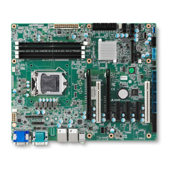
IMB-M45 Introduction The IMB-M45 is an ATX motherboard supporting Intel® Xeon™ E workstation and 8th and 9th Generation Intel® Core™ i7/i5/i3 desktop processors, an Intel® C246 Chipset, and 5 PCIe expansion slots to provide a cost- competitive embedded computing solution. With high-speed data transfer interfaces such as PCIe 3.0/2.0, USB 3.1... - Page 10 This page intentionally left blank. Introduction...
-
Page 11: Specifications
IMB-M45 Specifications Core System CPU: Intel® Xeon™ E or 8 Generation Intel® Core™ i7/i5/i3 Desktop Processor, LGA1151 socket • Intel® Xeon™ E-2278GE, 3.3GHz, 16M Cache, 80W TDP, LGA1151, DDR4 2666MHz support, (8C/16T) • Intel® Xeon™ E-2226GE, 3.4GHz, 12M Cache, 80W TDP, LGA1151, DDR4 2666MHz support, (6C/6T) •... -
Page 12: I/O Interface
I/O Interface Expansion slots: • Signals If PEG2 is occupied, PEG1 is PCIe x8 Gen3, PEG2 is PCIe x8 Gen3 If PEG2 is not occupied, PEG1 is PCIe x16 Gen3, and PEG2 has no signal PCIe1: PCIe x4 Gen3, PCIe2: PCIe x4 Gen3, PCIe3: PCIe x4 Gen3 PCI1/ PCI2: PCI 2.2 •... -
Page 13: Humidity
IMB-M45 Humidity 60° C at 95% RH, non-condensing Certificate (EMC) CE/FCC Class B Form Factor ATX: 305 mm x 244 mm (W x L) 2.10 Operating Systems Microsoft® Windows® 10, 64-bit Microsoft® Windows® Server 2016, 64-bit OpenSUSE Leap 15.1, 64-bit Fedora 30, 64-bit Ubuntu 18.10, 64 bit... -
Page 14: Functional Block Diagram
2.11 Functional Block Diagram One PCIe Gen3 x16 or Two PCIe Gen3 x8 Xeon™ E or Dual Channel 8th/9th Gen HDMI Intel® Core™ DDR4-2400/2666 PTN3355BS Line out/in, Mic in RJ45 ALC892 or I219LM ALC888S RJ45 PCIe x1 I210AT PCI 1-2 PCIe x1 IT8892E SATA Gen3 x6... -
Page 15: Mechanical Layout
IMB-M45 Mechanical Layout Connector Locations Figure 2: IO Panel Connector Locations Table 1: IO Panel Connector Definitions IO Panel Connectors Item Description VGA Port HDMI Port Display Port COM1 RS-232/422/485, RI pin with Power Jumper Select COM2 RS-232/422/485 LAN1 2x USB3.1 Gen2 port LAN2 2x USB3.1 Gen2 port... -
Page 16: Figure 3: Onboard Connector Locations
Figure 3: Onboard Connector Locations Table 2: Onboard Connector Definitions Onboard Connectors Item Description Remarks ATX POWER 8-pin ATX12V1 CPU_FAN CPU_FAN1 ATX POWER 24-pin EATXPWR1 SATA12 SATA1 (TOP) and SATA2 SATA34 SATA3 (TOP) and SATA4 SATA56 SATA5 (TOP) and SATA6 SYS_FAN1 SYS_FAN1 USB1314... - Page 17 IMB-M45 Onboard Connectors COM4 COM4 USB3.0 pin header USB56 COM3 COM3 PRINT PORT LPT1 GPIO JDIO1 PEG1 PCIEx16_1 PEG2 PCIEx16_2 PCIEx4 PCIEx4_1 PCIEx4 PCIEx4_2 PCIEx4 PCIEx4_3 PCI1 PCI1 PCI2 PCI2 FP_AUDIO1 AAFP1 COM1 RS-232/422/485 select JSETCOM1 COM2 RS-232/422/485 select JSETCOM2...
-
Page 18: Mechanical Dimensions
Mechanical Dimensions Top View Dimensions: mm Figure 4: Mechanical Dimensions Side View Dimensions: mm Figure 5: Mechanical Dimensions - IO Panel Mechanical Layout... -
Page 19: Connector Pinouts
IMB-M45 Connector Pinouts See 3.1 Connector Locations on page 7 for connector locations. Rear IO Connectors 4.1.1 HDMI Signal Signal HDMI1_CON_DP2 HDMI1_CON_DN2 HDMI1_CON_DP1 HDMI1_CON_DN1 HDMI1_CON_DP0 HDMI1_CON_DN0 HDMI1_CON_CKP HDMI1_CON_CKN HDMI1_DDC_CLK HDMI1_DDC_DATA +5V_HDMI HDMI1_CON_HPD 4.1.2 Display Port Signal Signal CN_DDPx0+ CN_DDPx0- CN_DDPx1+... - Page 20 4.1.3 VGA Connector Signal Signal VGA_CON_RED VGA_CON_GREEN VGA_CON_BLUE +5V_HDMI VGA_DDCDAT VGA_CON_HS VGA_CON_VS VGA_DDCCLK 4.1.4 USB Connectors USB 3.1 Gen2, USB 3.0, USB 2.0 Signal +5 VDC USB D- USB2.0 USB D+ Signal StdA_SSRX- StdA_SSRX+ GND_DRAIN StdA_SSTX- StdA_SSTX+ VUSB Connector Pinouts...
- Page 21 IMB-M45 Signal +5V_USB12 USB_CM_N1 9 8 7 6 5 USB_CM_P1 1 2 3 4 USB3_RX_CM_N1 USB3.0 USB3_RX_CM_P1 USB3_TX_CM_N1 USB3_TX_CM_P1 4.1.5 COM 1-2 Connector Stack (Top connector COM1, Bottom connector COM2) Signal RS-232 RS-422 RS-485 DCD# Tx/Rx- Tx/Rx+ N /A DTR#...
- Page 22 4.1.6 Ethernet Connectors (LAN1, LAN2) Dual 10/100/1000Mbit/s LAN Ethernet controllers based on Intel® i219LM/i210AT, support PXE and WOL over both LANs.In BIOS menu only LAN 1 have wake on LAN option 10BASE- 1000BASE-T T/100BASE-TX LAN_MDI0+ LAN_MDI0- LAN_MDI1+ LAN_MDI2+ LAN_MDI2- LAN_MDI1- LAN_MDI3+ LAN_MDI3- LED1 (Speed)
-
Page 23: Internal Connectors
IMB-M45 Internal Connectors 4.2.1 PS2 Combo connector Signal KB_DAT KB_CLK MS_DAT MS_CLK +5V_DUAL 4.2.2 USB5,6 Signal Signal +5 VDC Port1_RX- Port1_RX+ Port1_TX- Port1_TX+ Port1_D - Port1_D + Port2_D + Port2_D - Port2_TX+ Port2_TX- Port2_RX+ Port2_RX- +5 VDC KEY (no pin) 4.2.3... - Page 24 4.2.4 SATA1, SATA2, SATA3, SATA4, SATA5, SATA6 Signal Description Ground Transmit diff data – positive Transmit diff data – negative Ground Receive diff data – negative Receive diff data – positive Ground 4.2.5 COM3, COM4, COM5, COM6 Serial Port is over-current protected. Signal Description Signal...
- Page 25 IMB-M45 4.2.7 FP_AUDIO1 Signal Signal [Port 2] SENSE_RETURN_B Line-In Port2 Left Line-In Port2 Right GND_A MIC-In Port2 Left SIDE OUT Right MIC-In Port2 Right SIDE OUT Left 4.2.8 JCASE1 Signal Description Ground SIO_CASEOPEN# Case open signal 4.2.9 CPU_FAN1, SYS_FAN1, SYS_FAN2...
- Page 26 4.2.11 EATXPWR1 Signal Signal +3.3 V +3.3 V +3.3 V -12 V Ground Ground +5 V PS-ON# (power supply remote on/off) Ground Ground +5 V Ground Ground Ground PWRGD (Power Good) No connect +5 V (Standby) +5 V +12 V +5 V +12 V +5 V...
- Page 27 IMB-M45 4.2.14 SPI1 Signal Signal VCC3 SPI_CS# SPI_CLK SPI_MISO SPI_MOSI HOLD# 4.2.15 JPSON1 (Default 2-3) Signal Description PANSWIN# Power switch signal PSON_AT AT mode signal 4.2.16 JDIO1 (TTL High:3.3V / TTL Low:0V) Signal Signal DIO1 DIO17 DIO2 DIO18 DIO3 DIO19...
- Page 28 4.2.17 JSETCOM1, JSETCOM2 Signal Signal UART1_RXD COM1_RXD485 UART1_RXD COM1_RXD422 UART1_RXD COM1_RXD232 COM1_DCD# COM1_TX COM1_CN_DCD# COM1_CN_TX TXD485#1 RXD485P1 COM1_RX COM1_DTR# COM1_CN_RX COM1_CN_DTR# TXD485P1 RXD485#1 4.2.18 JCMOS1 (Default 1-2) Signal Description RTCRST# Reset CMOS 4.2.19 JPW2 (Default: 3-4) Signal Signal JDIO1. Pin40 JDIO1.
- Page 29 IMB-M45 4.2.22 JSMB1 Signal Description NC/+3.3V/+5V select SMB_DATA SMBUS data SMB_CLK SMBUS clock Ground 4.2.23 JI2C1 Signal Description NC/+3.3V/+5V select I2C_DATA I2C data I2C_CLK I2C clock Ground Connector Pinouts...
-
Page 30: Jumper And Switch Settings
Jumper and Switch Settings Table 3: Jumper and Switch Definitions Jumper Block Item Description Remarks JCMOS1 One 1x3 2.54mm pin header Normal (Default) 1-2 (default) = Normal, 2-3 = Clear CMOS Clear CMOS JPSON1 One 1x3 2.54mm pin header AT mode 1-2 = AT Mode;... - Page 31 IMB-M45 Jumper Block COM1_S1~S4 master/slave and terminal selection COM2_S1~S4 master/slave and terminal selection Connector Pinouts...
- Page 32 Jumper Block JPW2 One 2x3 2.0mm pin header NC (Default) NC (default)/+5V/+12V +12V JPW1 One 2X3 2.0mm pin header NC (Default) NC (default)/+5V/+3.3V +3.3V Connector Pinouts...
- Page 33 IMB-M45 Jumper Block JPW3 One 2x3 2.0mm pin header NC (Default) NC (default)/+5V/+3.3V +3.3V Connector Pinouts...
- Page 34 This page intentionally left blank. Connector Pinouts...
-
Page 35: Driver Installation
IMB-M45 Driver Installation Download the requisite drivers for your system from the IMB-M45 product page at: https://www.adlinktech.com/Products/Industrial_Motherboards_SBCs/ATXMotherboards/IMB-M45 Driver Installation... - Page 36 This page intentionally left blank. Driver Installation...
-
Page 37: System Resources
IMB-M45 System Resources System Memory Map Table 4: System Memory Map Address Range Address Range Size Description (4GB-2MB) FFE00000 – FFFFFFFF 2 MB High BIOS Area (4GB-18MB) – (4GB-17MB-1) FEE00000 – FEEFFFFF 1 MB MSI Interrupts (4GB-20MB) – (4GB-19MB-1) FEC00000 – FECFFFFF... - Page 38 Hex Range Device 0063-0063 Motherboard resources 0065-0065 Motherboard resources 0067-0067 Motherboard resources 0070-0070 Motherboard resources 0080-0080 Motherboard resources 0092-0092 Motherboard resources 00B2-00B3 Motherboard resources 0680-069F Motherboard resources FFFF-FFFF Motherboard resources 1800-18FE Motherboard resources 164E-164F Motherboard resources 0040-0043 System timer 0050-0053 System timer 0070-0077 System CMOS/real time clock...
-
Page 39: Interrupt Request (Irq) Lines
IMB-M45 Interrupt Request (IRQ) Lines 6.3.1 IRQ Lines PIC Mode Table 6: IRQ Lines PIC Mode IRQ# Device System timer COM2 COM1 COM3, COM4 System CMOS/real time clock COM5, COM6 Numeric data processor Intel Serial IO GPIO Host Controller Intel Chipset Smbus HD Audio Controller Note: These IRQs can be used for PCI devices when onboard device is disabled. -
Page 40: Pci Features
PCI Features 6.4.1 PCI Configuration Space Map Table 8 PCI Configuration Space Map Device Function Routing Description Number Number Number Intel Host Bridge Internal Intel VGA Controller Internal Intel USB 3.0 XHCI Internal Intel Data acquisition/signal process Internal Intel Communication device Internal Intel AHCI 1.0 controller Internal... -
Page 41: Smbus Slave Addresses
IMB-M45 6.4.2 Table 9 PCI Interrupt Routing Map LpcBridge High SMBus PCIE Root PCIE Root Port PCIE Root Line Definition Port #2 #3 (LAN3) Port #4 Audio (IT8892) (LAN4) Int0 INTA:16 INTA:16 INTA:16 INTB:17 INTC:18 INTD:19 Int1 INTB:17 INTC:18 INTD:19... - Page 42 This page intentionally left blank. System Resources...
-
Page 43: Bios Setup
IMB-M45 BIOS Setup Menu Structure This section presents the primary menus of the BIOS Setup Utility. Use the following table as a quick reference for the contents of the BIOS Setup Utility. The subsections describe the submenus and options for each menu item. -
Page 44: 7.2 Main Menu
Feature Options Description BIOS Vendor American Megatrends Core Version x.xx Compliancy UEFI x.x; PI x.x Project Version IMB-M45 x.xx.xx Build Date and Time mm/dd/yyyy hh:mm:ss Access Level Administrator Memory Information Total Memory xxxx MB Memory Frequency xxxx MHz Power Type... -
Page 45: Advanced Menu
IMB-M45 Advanced Menu This menu contains the settings for most of the user interfaces in the system. 7.3.1 Advanced > CPU Configuration Feature Options Description Type Info Only CPU type Info Only CPU ID Speed Info Only CPU Speed (xxxx MHz) - Page 46 Feature Options Description Package C state limit Maximum Package C State Limit Setting. Auto CPU Default CPU Default: Leaves to Factory default value. Auto: Initializes to deepest available Package C State Limit. C0/C1 7.3.2 Advanced > PCH-FW Configuration Feature Options Description ME Firmware Version Info Only...
- Page 47 IMB-M45 7.3.4 Advanced > NCT6106D SuperIO Configuration Feature Options Description Serial Port 1 Configuration► Submenu Sets Parameters of Serial Port 1 (COMA) Serial Port 2 Configuration► Submenu Sets Parameters of Serial Port 2 (COMB) Serial Port 3 Configuration► Submenu Sets Parameters of Serial Port 3 (COMC) Serial Port 4 Configuration►...
- Page 48 7.3.7 Advanced > NCT6106D SuperIO Configuration > Serial Port 3 Configuration Feature Options Description Serial Port Disabled Enables or Disables Serial Port (COM) Enabled Device Settings IO=3E8h Serial Port device settings IRQ=5 Change Settings Selects optimal settings for Super IO Device Auto 7.3.8 Advanced >...
- Page 49 IMB-M45 7.3.11 Advanced > NCT6106D SuperIO Configuration > Parallel Port Configuration Parallel Port Options Note Parallel Port Disabled Enables or Disables Parallel Port (LPT/LPTE) Enabled Device Settings Info Only Serial Port device settings Change Settings Selects optimal settings for Super IO Device...
- Page 50 7.3.14 Advanced > Smart Fan > Smart Fan Mode Configuration – Manual Mode Feature Options Description SYS Smart Fan1 Mode SYS Smart Fan1 Mode Manual Mode Thermal Cruise Mode SYS expect PWM Output/DC Voltage System FAN1 expect PWM Output/DC Voltage CPU Smart Fan Mode CPU Smart Fan Mode Manual Mode...
- Page 51 IMB-M45 7.3.18 Advanced > Serial Port Console Redirection > Console Redirection Settings Feature Options Description Terminal Type VY100 Type Select VT100+ VT-UTF8 ANSI Bits per second 9600 Select serial port transmission speed. 19200 38400 57600 115200 Data Bits Data Bits...
- Page 52 7.3.19 Advanced > Intel TXT Information Feature Options Description Chipset Info Only BIOS Acm Info Only Chipset Txt Info Only CPU Txt Info Only Error Code Info Only Class Code Info Only Major Code Info Only Minor Code Info Only 7.3.20 Advanced >...
- Page 53 IMB-M45 7.3.22 Advanced > NVMe Configuration Feature Options Description NVMe controller and Drive information Info Only NVMe Device Options Settings Show device Info Only 7.3.23 Advanced > USB Configuration Feature Options Description USB Devices Show current USB devices Legacy USB Support Enables or Disables Legacy USB support.
-
Page 54: Chipset Menu
Chipset Menu This menu contains settings for other user interfaces in the system. 7.4.1 Chipset > System Agent (SA) Configuration Feature Options Description SA PCIe Code Version Info Only VT-d Capability Info Only Memory Configuration► Submenu Memory Configuration Parameters Graphics Configuration► Submenu Graphics Configuration PEG Port Configuration►... - Page 55 IMB-M45 7.4.3 Chipset > System Agent (SA) Configuration > Graphics Configuration Feature Options Description Selects which of IGFX/PEG/PCIE Graphics device should be Primary Display Auto Primary Display IGFX PCIE Internal Graphics Keeps IGFX enabled based on the setup options Auto...
- Page 56 7.4.4 Chipset > System Agent (SA) Configuration > PEG port Configuration Feature Options Description PEG 0:1:0 Enable Root port Disabled Enables or Disables the Root Port Enabled Auto Max Link Speed Configures PEG 0:1:0 Max Speed Auto Gen1 Gen2 Gen3 PEG 0:1:1 Enable Root port Disabled...
- Page 57 IMB-M45 7.4.5 Chipset > PCH-IO Configuration Feature Options Description PCI Express Configuration► Submenu PCI Express Configuration settings SATA And RST Configuration► Submenu SATA Device Options Settings USB Configuration► Submenu USB Configuration settings HD Audio Configuration► Submenu HD Audio Subsystem Configuration settings Serial IO Configuration►...
- Page 58 7.4.6 Chipset > PCH-IO Configuration > PCI Express Configuration Feature Options Description PCI Express Configuration Info only PCI Express Root Port 3(LAN3) PCI Express Root Port 4(LAN4) PCIE Port 2 is assigned to IT8892 PCI Express Root Port 5( x4, slot 4 )► Submenu PCI Express Root Port 5 Settings.
- Page 59 IMB-M45 7.4.8 Chipset > PCH-IO Configuration > SATA Configuration SATA Configuration Options Note SATA Controller(s) Disabled Enables or Disables SATA Device Enabled SATA Mode Determines how SATA controllers AHCI operate. Intel RST Premium with Intel Optane System Acceleration Serial ATA Port 1...
- Page 60 7.4.9 Chipset > PCH-IO Configuration > USB Configuration Feature Options Description XHCI Disable Compliance Mode Enables or Disables XHCI Disable Compliance Mode Disabled Enabled USB12 Standby Power Support Disabled Enables or Disables USB standby power Enabled USB34 Standby Power Support Disabled Enables or Disables USB standby power Enabled...
-
Page 61: Security Menu
IMB-M45 Security Menu Feature Options Description Administrator Password Enter password Set Administrator Password User Password Enter password Set User Password BIOS Setup... -
Page 62: Boot Menu
Boot Menu Feature Options Description Boot Configuration Info Only Setup Prompt Timeout 1 (seconds) Number of seconds to wait for setup activation key. 65535(0xFFFF) means infinite waiting. Bootup NumLock State Select the keyboard NumLock state. Quiet Boot Disabled Enables or Disables Quiet Boot option Enabled Support Native Resolution Disabled... -
Page 63: Save & Exit Menu
IMB-M45 Save & Exit Menu Save & Exit Options Note Save Changes and Exit Exits system setup after saving the changes. Discard Changes and Exit Exits system setup without saving any changes. Save Changes and Reset Resets the system after saving the changes. - Page 64 This page intentionally left blank. BIOS Setup...
-
Page 65: Safety Instructions
IMB-M45 Safety Instructions Read and follow all instructions marked on the product and in the documentation before you operate your system. Retain all safety and operating instructions for future use. • Please read these safety instructions carefully. • Please keep this User‘s Manual for later reference. -
Page 66: Getting Service
5215 Hellyer Avenue, #110, San Jose, CA 95138, USA Tel: +1-408-360-0200 Toll Free: +1-800-966-5200 (USA only) Fax: +1-408-360-0222 Email: info@adlinktech.com ADLINK Technology (China) Co., Ltd. Address: 300 Fang Chun Rd., Zhangjiang Hi-Tech Park, Pudong New Area Shanghai, 201203 China Tel: +86-21-5132-8988 Fax: +86-21-5132-3588 Email: market@adlinktech.com...
Need help?
Do you have a question about the IMB-M45 and is the answer not in the manual?
Questions and answers