
Related Manuals for ADLINK Technology IMB-T10


Summary of Contents for ADLINK Technology IMB-T10
- Page 1 IMB-T10 Intel® Atom™ Processor D2550 Industrial Mini-ITX Motherboard User’s Manual Manual Rev.: 2.00 Revision Date: February 24, 2014 Part No: 50-1X003-1000 Advance Technologies; Automate the World.
- Page 2 Revision History Revision Release Date Description of Change(s) 2.00 2014/02/24 Initial release Revision History...
-
Page 3: Preface
IMB-T10 Preface Copyright 2014 ADLINK Technology Inc. This document contains proprietary information protected by copy- right. All rights are reserved. No part of this manual may be repro- duced by any mechanical, electronic, or other means in any form without prior written permission of the manufacturer. - Page 4 Using this Manual Audience and Scope The IMB-T10 User’s Manual is intended for hardware technicians and systems operators with knowledge of installing, configuring and operating industrial grade computers. Manual Organization This manual is organized as follows: Preface: Presents copyright notifications, disclaimers, trade- marks, and associated information on the proper usage of this document and its associated product(s).
- Page 5 IMB-T10 Conventions Take note of the following conventions used throughout this manual to make sure that users perform certain tasks and instructions properly. Additional information, aids, and tips that help users perform tasks. NOTE: NOTE: Information to prevent minor physical injury, component dam- age, data loss, and/or program corruption when trying to com- plete a task.
- Page 6 This page intentionally left blank. Preface...
-
Page 7: Table Of Contents
IMB-T10 Table of Contents Revision History..............ii Preface ..................iii List of Figures ................ ix List of Tables................xi 1 Introduction ................ 1 Package Contents ............... 1 Overview................2 Features................2 Specifications............... 3 Block Diagram ..............5 Functional Description ............6 Mechanical Dimensions............ - Page 8 Introduction ................ 31 4.1.1 UEFI Menu Bar .............. 31 4.1.2 Navigation Keys............. 32 Main Screen............... 33 Advanced Screen............... 34 4.3.1 CPU Configuration............36 4.3.2 CPU Configuration............37 4.3.3 Storage Configuration............ 39 4.3.4 Super IO Configuration ..........40 4.3.5 ACPI Configuration ............41 4.3.6 USB Configuration ............
-
Page 9: List Of Figures
IMB-T10 List of Figures Figure 1-1: IMB-T10 Block Diagram........... 5 Figure 1-2: IMB-T10 Board Dimensions..........8 Figure 2-1: IMB-T10 Rear I/O Layout..........9 Figure 2-2: IMB-T10 Board Layout........... 14 List of Figures... - Page 10 This page intentionally left blank. List of Figures...
-
Page 11: List Of Tables
IMB-T10 List of Tables Table 1-1: IMB-T10 General Specifications ........4 Table 2-1: Board Layout Legend ............ 15 List of Tables... - Page 12 This page intentionally left blank. List of Tables...
-
Page 13: Introduction
IMB-T10 Introduction This chapter will introduce the IMB-T10, its features, specifica- tions, functional description, and mechanical layout. 1.1 Package Contents Please check that your package contains the items below. If you discover damaged or missing items, please contact your vendor. -
Page 14: Overview
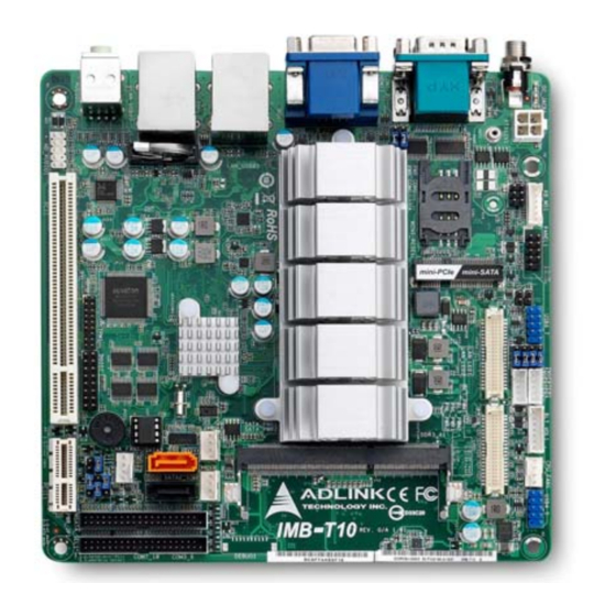
Intel® Atom™ Processor D2550 built on 32-nm pro- cess technology in Micro-FCBGA118 packaging technologies and the Mobile Intel® NM10 Express Chipset. The IMB-T10 is ideal for embedded applications requiring fanless operation and ultra-low power consumption in a standard small form factor motherboard with a complete set of I/O functions and high-bandwidth network connectivity. -
Page 15: Specifications
IMB-T10 1.4 Specifications System Intel® Atom™ Processor D2550 • 1.86 GHz core frequency • 1024KB L2 cache • FCBGA559 package Chipset • Intel® NM10 Express Chipset Memory • DDR3 800/1066 SO-DIMM (4GB max.) • 1x 204-pin SO-DIMM slot BIOS • AMI® uEFI BIOS, 16Mbit SPI Flash ROM Audio •... - Page 16 • 170 mm x 170 mm (L x W) Operating Temp. • 0°C to 60°C Storage Temp. • -20ºC to 80ºC Rel. Humidity • 10 - 90% RH Safety • CE, FCC Class A Table 1-1: IMB-T10 General Specifications Introduction...
-
Page 17: Block Diagram
NUVOTON Audio Codec Line NTC6627UD RTL ALC887 Rear COM Ports GPIO Header COM_1(RS232/422/485) (2x8, 2.0mm Header) COM_2(RS232) 7 GPI 7 GPO Internal COM Ports +5V & GND (2x20, 2.0mm Header) COM_3(RS232) COM_4(RS232) COM_5(RS232) COM_6(RS232) Figure 1-1: IMB-T10 Block Diagram Introduction... -
Page 18: Functional Description
1.86 GHz core speed and 10 watts TDP Hyper-Threading Technology Intel® NM10 Express Chipset The IMB-T10 is based on the Intel® NM10Express Chipset It pro- vides rich I/O capabilities and flexibility via high-bandwidth inter- faces such as PCI Express, PCI, Serial ATA, and Hi-Speed USB 2.0 connectivity, and also provides an Intel®... - Page 19 Serial ATA Storage is efficient and secure with the Serial ATA interface. Utiliz- ing the Intel® NM10, the IMB-T10 supports two Serial ATA devices capable of reading/writing data at up to 3 Gb/s. The SATA specifi- cation improves chassis airflow via thinner and more flexible cables with lower pin count.
-
Page 20: Mechanical Dimensions
1.7 Mechanical Dimensions Figure 1-2: IMB-T10 Board Dimensions Introduction... -
Page 21: Hardware Information
IMB-T10 Hardware Information 2.1 Rear I/O Layout Figure 2-1: IMB-T10 Rear I/O Layout COM port (COM2) VGA port LAN RJ-45 port LAN RJ-45 port Line-out (green) Mic-in (pink) USB 2.0 Ports (USB23) USB 2.0 Ports (USB01) HDMI port COM port (COM1) -
Page 22: Rear I/O Connector Pin Definitions
2.2 Rear I/O Connector Pin Definitions VGA Connector. Signal Name Pin # Pin # Signal Name Green Blue VCC pull-up VCC pull-up DDC2B DATA HSYNC VSYNC DDC2B CLK USB Connectors Pin # Signal Name USB- USB+ Hardware Information... - Page 23 IMB-T10 LAN Port (RJ-45) This port allows gigabit connection to a Local Area Network (LAN) using a network hub. The LAN port comes with two LEDs to indi- cate link, activity and speed. Refer to the tables below for the LAN port pin and LED definitions.
- Page 24 COM1/2 Connectors (DB-9) Pin # RS-232 RS-422* RS-485* DCD-L RTX- RTX+ DTR-L DSR-L RTS-L CTS-L RI-L *RS-422/485 signals supported on COM1 only. See COM1 Mode jumper settings below and 2.3 Board Layout on p. 14 for J3 location. NOTE: NOTE: COM1 RS-232/422/485 Mode Select (J3) Pins RS-232...
- Page 25 IMB-T10 HDMI Connector Pin # Signal Pin # Signal TMDS Data2+ TMDS Data2 Shield TMDS Data2– TMDS Data1+ TMDS Data1 Shield TMDS Data1– TMDS Data0+ TMDS Data0 Shield TMDS Data0– TMDS Clock+ TMDS Clock Shield TMDS Clock– Reserved DDC/CEC Ground...
-
Page 26: Board Layout
RJ-45 B IOS B: USB 3 C hip CHA_F AN1 AUDI O CODE C BUZZ1 CI 2 CI 1 MSA TA_SEL 1 D GIO1 TPM1 PWR_JP 1 CLRCMOS 1 HD_AUDIO1 PCI1 PCIE 1 Figure 2-2: IMB-T10 Board Layout Hardware Information... - Page 27 IMB-T10 ATX 12V Power Connector (Input/Output 10A) COM1 Mode Jumper (J3) Keyboard/Mouse Connector System Panel Header LAN Active LED Header (LAN LED1) LAN Active LED Header (LAN LED2) USB 2.0 Header (USB6_7) BLT_PWM1 & BLT_PWM2, PNL_PWR1 & PNL_PWR2 Inverter Connector (Inverter1)
-
Page 28: Onboard Connector Pin Definitions
2.4 Onboard Connector Pin Definitions LVDS Panel Connector (LVDS1/2) Pin # Signal Pin # Signal VDD_PWR1 VDD_PWR1 LBKLT_EN1 LBKLT_CTL1 DPLVD_A_DATA1 DPLVD_A_DATA0 DPLVD_A_DATA1# DPLVD_A_DATA0# DPLVD_A_DATA3 DPLVD_A_DATA2 DPLVD_A_DATA3# DPLVD_A_DATA2# DPLVD_B_DATA1 DPLVD_B_DATA0 DPLVD_B_DATA1# DPLVD_B_DATA0# DPLVD_B_DATA3 DPLVD_B_DATA2 DPLVD_B_DATA3# DPLVD_B_DATA2# DPLVD_B_CLK DPLVD_A_CLK DPLVD_B_CLK# DPLVD_A_CLK# +12V +12V Hardware Information... - Page 29 IMB-T10 SATA Signal Connectors (SATA2_1/2) Pin # Signal SATA Power Output Connectors (SATA_PWR1/2) Hardware Information...
- Page 30 COM3~6 Connector (COM3_6) Pin # Signal Pin # Signal DDCD#_3 DDSR#_3 RRXD_3 RRTS#_3 TTXD_3 CCTS#_3 DDTR#_3 RRI#3 DDCD#_4 DDSR#_4 RRXD_4 RRTS#_4 TTXD_4 CCTS#_4 DDTR#_4 RRI#4 DDCD#_5 DDSR#_5 RRXD_5 RRTS#_5 TTXD_5 CCTS#_5 DDTR#_5 RRI#5 DDCD#_6 DDSR#_6 RRXD_6 RRTS#_6 TTXD_6 CCTS#_6 DDTR#_6 RRI#6 Hardware Information...
- Page 31 IMB-T10 COM7~10 Connector (COM7_10) Pin # Signal Pin # Signal DDCD#_A DDSR#_A RRXD_A RRTS#_A TTXD_A CCTS#_A DDTR#_A RRIXA DDCD#_B DDSR#_B RRXD_B RRTS#_B TTXD_B CCTS#_B DDTR#_B RRI#B DDCD#_C DDSR#_C RRXD_C RRTS#_C TTXD_C CCTS#_C DDTR#_C RRI#C DDCD#_D DDSR#_D RRXD_D RRTS#_D TTXD_D CCTS#_D...
- Page 32 CPU/Chassis Fan Connectors (CPU/CHA__FAN1) Pin # Signal Fan power (+12V) Fan Tachometer Fan Speed Control A 3-pin fan connector (no fan speed control) can be connected to pins 1-3. NOTE: NOTE: System Panel Header (PANEL1) PWRBTN (Power Switch): Connect to the power switch on the chassis front panel.
- Page 33 IMB-T10 HDLED (Hard Drive Activity LED): Connect to the hard drive activ- ity LED on the chassis front panel. The LED is on when the hard drive is reading or writing data. The front panel design may differ by chassis. A front panel module mainly consists of power switch, reset switch, power LED, hard drive activity LED, speaker and etc.
- Page 34 Chassis Intrusion Headers Header Status Function Close Active case open Open Normal Close Normal Open Active case open TPM Header (TPM1) Keyboard/Mouse Connector (KB_MS1) Pin # Signal KBCLK KBDATA MSDATA MSLCK Hardware Information...
- Page 35 IMB-T10 ATX 12V Power Connector (ATX12V1) Pin # Signal +12V DC +12V DC LAN Active LED Headers (LAN LED1/2) Inverter Connectors (Inverter1/2) Pin # Signal +12V LBKLT_EN LBKLT_CTL Backlight Volume Control (BLT_VOL1) Pin # Signal PWRDN LVDS1 BLUP LVDS1 BLDW...
- Page 36 Digital IO Header (DGIO1) Pin # Signal Pin # Signal Digital Output 0 Digital Input 0 Digital Output 1 Digital Input 1 Digital Output 2 Digital Input 2 Digital Output 3 Digital Input 3 Digital Output 4 Digital Input 4 Digital Output 5 Digital Input 5 Digital Output 6...
-
Page 37: Jumper Settings
IMB-T10 2.5 Jumper Settings Clear CMOS Header CLRCMOS1 allows you to clear the data in CMOS. To clear and reset the system parameters to default setup, please turn off the computer and unplug the power cord from the power supply. After waiting for 15 seconds, use a jumper cap to short pin2 and pin3 on CLRCMOS1 for 5 seconds. - Page 38 mSATA Mode (MSATA_SEL1 Jumper, see p. 14, No. 23) Pin # Function Mini-PCIE + SATA2_2 mSATA (no SATA2_2) ATX/AT Mode Selection (PWR_JP1, see p. 14, No. 24) Pin # Function AT Mode ATX Mode COM Power (see p. 14, PWR_COM1: No. 30; PWR_COM2: No. 31) Pin # Function Reserved Hardware Information...
-
Page 39: Getting Started
IMB-T10 Getting Started The IMB-T10 is a Mini-ITX form factor (6.7" x 6.7", 17.0 x 17.0 cm) motherboard. Before you install the motherboard, check the con- figuration of your chassis to ensure that the motherboard fits into Make sure to unplug the power cord before installing or remov- ing the motherboard. -
Page 40: Installation Of Memory Modules (So-Dimm)
3.3 Installation of Memory Modules (SO-DIMM) This motherboard provides one 204-pin DDR3 (Double Data Rate 3) SO-DIMM slot. Step 1. Align a DIMM on the slot such that the notch on the DIMM matches the break on the slot. The DIMM only fits in one orientation. Forcing the DIMM into the slot It will cause permanent damage to the motherboard and the DIMM. -
Page 41: Driver Installation
Step 5. Fasten the card to the chassis with screws. Step 6. Replace the system cover. 3.5 Driver Installation The IMB-T10 drivers for Windows 7 32-bit are located in the fol- lowing files that can be downloaded from the ADLINK website (http://www.adlinktech.com): Chipset \1.Chipset\Intel\(v9.2.2.1034)\... - Page 42 3. Install the Display driver and utilities by running the program \2.VGA\Win7_32\(v8.0.0.6.1082)\setup.exe. Follow the instructions given and reboot when instructed. 4. Install the Audio driver by running the program \3.Audio\ 6937_PG367_Win8_Win7_Vista_XP_WHQLed\setup.exe. Follow the instructions given and reboot if required. 5. Install the LAN driver by running the program \4.LAN\ WIN7\Install_Win7_7069_03212013\LAN\Win7\setup.exe.
-
Page 43: Bios Setup
IMB-T10 BIOS Setup 4.1 Introduction This section explains how to use the UEFI SETUP UTILITY to configure your system. The UEFI chip on the motherboard stores the UEFI SETUP UTILITY. You may run the UEFI SETUP UTILITY when you start the computer. Please press <F2> or <Del> during the Power-On-Self-Test (POST) to enter the UEFI SETUP UTIL- ITY, otherwise POST will continue with its test routines. -
Page 44: Navigation Keys
4.1.2 Navigation Keys The following table describes the functions of each navigation key. Navigation key(s) Functional Description ← → Moves cursor left or right to select Screens ↑ ↓ Moves cursor up or down to select items Choose between options of the selected item <Enter>... -
Page 45: Main Screen
IMB-T10 4.2 Main Screen When you enter the UEFI SETUP UTILITY, the Main screen will appear and display the system overview. BIOS Setup... -
Page 46: Advanced Screen
4.3 Advanced Screen In this section, you may set the configurations for the following items: CPU Configuration, Chipset Configuration, Storage Config- uration, Super IO Configuration, ACPI Configuration and USB Configuration. Setting incorrect values in this section may cause the system to malfunction. - Page 47 IMB-T10 the Instant Flash utility, the utility will show the UEFI files and their respective information. Select the proper UEFI file to update your UEFI, and reboot your system after the UEFI update process com- pletes. BIOS Setup...
-
Page 48: Cpu Configuration
4.3.1 CPU Configuration Intel Hyper-Threading Technology Enabling this feature requires a computer system with an Intel pro- cessor that supports Hyper-Threading technology and an operat- ing system that includes optimization for this technology, such as Microsoft® Windows® 7. Set to [Enabled] if using Microsoft® Win- dows®... -
Page 49: Cpu Configuration
IMB-T10 4.3.2 CPU Configuration LVDS1 Panel Type Selection Use this to select LVDS1 panel type. The default value is [1366x768/18- bit/1-ch/LED]. LVDS2 Panel Type Selection Use this to select LVDS2 panel type. The default value is [1366x768/18- bit/1-ch/LED]. Primary Graphics Adapter This allows you to select the boot graphic adapter priority. - Page 50 Restore on AC/Power Loss This allows you to set the power state after an unexpected AC/ power loss. If [Power Off] is selected, the AC/power remains off when the power recovers. If [Power On] is selected, the AC/power resumes and the system starts to boot up when the power recov- ers.
-
Page 51: Storage Configuration
IMB-T10 4.3.3 Storage Configuration SATA Mode Use this to select SATA mode. Configuration options: [IDE Mode], [AHCI Mode] and [Disabled]. The default value is [IDE Mode]. AHCI (Advanced Host Controller Interface), supports NCQ and other new features that will improve SATA disk performance, but IDE mode does not have these advantages. -
Page 52: Super Io Configuration
4.3.4 Super IO Configuration COM1~10 Configuration Use this to set parameters of COM1~10. WDT Timeout Reset This allows users to enable/disable the Watch Dog Timer timeout to reset system. The default value is [Disabled]. BIOS Setup... -
Page 53: Acpi Configuration
IMB-T10 4.3.5 ACPI Configuration Suspend to RAM Use this option to select whether to auto-detect or disable the Sus- pend-to- RAM feature. Select [Auto] will enable this feature if the OS supports it. S3 Video Repost Use this to enable/disable S3 Video Repost. The default value is [Enabled]. - Page 54 PCI Devices Power On Use this option to enable or disable PCI devices to turn on the sys- tem from the power-soft-off mode. RTC Alarm Power On Use this option to enable or disable RTC (Real Time Clock) to power on the system. USB Keyboard/Remote Power On Use this option to enable or disable USB Keyboard/Remote to power on the system.
-
Page 55: Usb Configuration
IMB-T10 4.3.6 USB Configuration USB 2.0 Controller Use this option to enable or disable the use of USB 2.0 controller. Legacy USB Support Use this option to select legacy support for USB devices. There are four configuration options: [Enabled], [Auto], [Disabled] and [UEFI Setup Only]. -
Page 56: Hardware Health Event Monitoring System
4.4 Hardware Health Event Monitoring System This section of the BIOS settings allows you to monitor the status of the hardware on your system, including the parameters of the CPU temperature, motherboard temperature, CPU fan speed, chassis fan speed, and critical voltage. CPU_FAN1 Setting This allows you to set the CPU fan (CPU_FAN1) speed. - Page 57 IMB-T10 Case Open Feature This allows you to enable or disable case open detection feature. The default value is [Disabled]. Clear Status This option appears only when the the system detects that the case has been opened. Use this option to keep or clear the record of previous chassis intrusions.
-
Page 58: Boot Screen
4.5 Boot Screen This section of the BIOS settings displays the available devices on your system for configuring the boot settings and boot priority. Setup Prompt Timeout This shows the number of seconds to wait for the setup activation key; 65535(0XFFFF) means waiting indefinitely. Bootup Num-Lock If this item is set to [On], it will automatically activate the Numeric Lock function after boot-up. -
Page 59: Security Screen
IMB-T10 4.6 Security Screen This section of the BIOS settings enables you to set, change or clear the supervisor/user password for the system. BIOS Setup... -
Page 60: Exit Screen
4.7 Exit Screen Save Changes and Exit Selecting this option will display the message “Save configuration changes and exit setup?” Select [OK] to save the changes and exit the UEFI SETUP UTILITY. Discard Changes and Exit Selecting this option will display the message “Discard changes and exit setup?”... - Page 61 IMB-T10 Load UEFI Defaults Load UEFI default values for all the setup questions. F9 key can be used for this operation. Launch EFI Shell from file system device Attempts to Launch EFI Shell application (Shell64.efi) from one of the available file system devices.
- Page 62 This page intentionally left blank. BIOS Setup...
-
Page 63: A Appendix: Wdt Sample Code
IMB-T10 Appendix A - WDT Sample Code #include "AsrCore.h" #include "AsrError.h" #include <tchar.h> #include <stdio.h> #pragma comment(lib, "AsrCore.lib") void DisplayError(int ErrorCode); void ShowError(bool bSuccess); int main(void) DWORD major, minor, release, build; AsrLibDllGetVersion(&major, &minor, &release, &build); _tprintf(_T("DLL Version [%d.%d.%d.%d]\n"), major, minor, release, build);... - Page 64 delete BIOSVersion; BIOSVersion = NULL; size = 0; ShowError(bSuccess = AsrLibGetPlatformName(NULL, &size)); TCHAR* PlatformName = new TCHAR[size + 1]; ShowError(bSuccess = AsrLibGetPlatformName(PlatformName, &size)); if (bSuccess) _tprintf(_T("Platform [%s]\n"), PlatformName); delete PlatformName; PlatformName = NULL; _tprintf(_T("Enable WDT timeout in 60 second...\n")); AsrLibWDSetConfig(60); _tprintf(_T("Press any key to reset WDT\n"));...
- Page 65 IMB-T10 break; case ERRLIB_DLL_NOT_INIT : _tprintf(_T("ERRLIB_DLL_NOT_INIT\n")); break; case ERRLIB_PLATFORM_UNSUPPORT : _tprintf(_T("ERRLIB_PLATFORM_UNSUPPORT\n")); break; case ERRLIB_API_UNSUPPORT : _tprintf(_T("ERRLIB_API_UNSUPPORT\n")); break; case ERRLIB_API_CURRENT_UNSUPPORT : _tprintf(_T("ERRLIB_API_CURRENT_UNSUPPORT\n")); break; case ERRLIB_LIB_INIT_FAIL : _tprintf(_T("ERRLIB_LIB_INIT_FAIL\n")); break; case ERRLIB_INVALID_PARAMETER : _tprintf(_T("ERRLIB_INVALID_PARAMETER\n")); break; case ERRLIB_INVALID_ID : _tprintf(_T("ERRLIB_INVALID_ID\n")); WDT Sample Code...
- Page 66 break; case ERRLIB_OUTBUF_RETURN_SIZE_INCORRECT : _tprintf(_T("ERRLIB_OUTBUF_RETURN_SIZE_INCORRECT\n") break; case ERRLIB_ARRAY_LENGTH_INSUFFICIENT : _tprintf(_T("ERRLIB_ARRAY_LENGTH_INSUFFICIENT\n")); break; case ERRLIB_THREAD_LOCKED : _tprintf(_T("ERRLIB_THREAD_LOCKED\n")); break; case ERRLIB_LIB_INVALID_VERSION : _tprintf(_T("ERRLIB_LIB_INVALID_VERSION\n")); break; default : tprintf(_T("UNKNOWN_ERROR\n")); void ShowError(bool bSuccess) if (!bSuccess) DisplayError(AsrLibDllGetLastError()) WDT Sample Code...
-
Page 67: Important Safety Instructions
IMB-T10 Important Safety Instructions For user safety, please read and follow all instructions, WARNINGS, CAUTIONS, and NOTES marked in this manual and on the associated equipment before handling/operating the equipment. Read these safety instructions carefully. Keep this user’s manual for future reference. - Page 68 Never attempt to fix the equipment. Equipment should only be serviced by qualified personnel. A Lithium-type battery may be provided for uninterrupted, backup or emergency power. Risk of explosion if battery is replaced with one of an incorrect type. Dispose of used batteries appropriately. WARNING: Equipment must be serviced by authorized technicians when:...
-
Page 69: Getting Service
5215 Hellyer Avenue, #110, San Jose, CA 95138, USA Tel: +1-408-360-0200 Toll Free: +1-800-966-5200 (USA only) Fax: +1-408-360-0222 Email: info@adlinktech.com ADLINK Technology (China) Co., Ltd. Address: (201203) 300 Fang Chun Rd., Zhangjiang Hi-Tech Park, Pudong New Area, Shanghai, 201203 China Tel: +86-21-5132-8988 Fax:... - Page 70 84 Genting Lane #07-02A, Cityneon Design Centre, Singapore 349584 Tel: +65-6844-2261 Fax: +65-6844-2263 Email: singapore@adlinktech.com ADLINK Technology Singapore Pte. Ltd. (Indian Liaison Office) Address: #50-56, First Floor, Spearhead Towers Margosa Main Road (between 16th/17th Cross), Malleswaram, Bangalore - 560 055, India Tel: +91-80-65605817, +91-80-42246107 Fax:...
Need help?
Do you have a question about the IMB-T10 and is the answer not in the manual?
Questions and answers