
Related Manuals for ADLINK Technology IMB-M46


Summary of Contents for ADLINK Technology IMB-M46
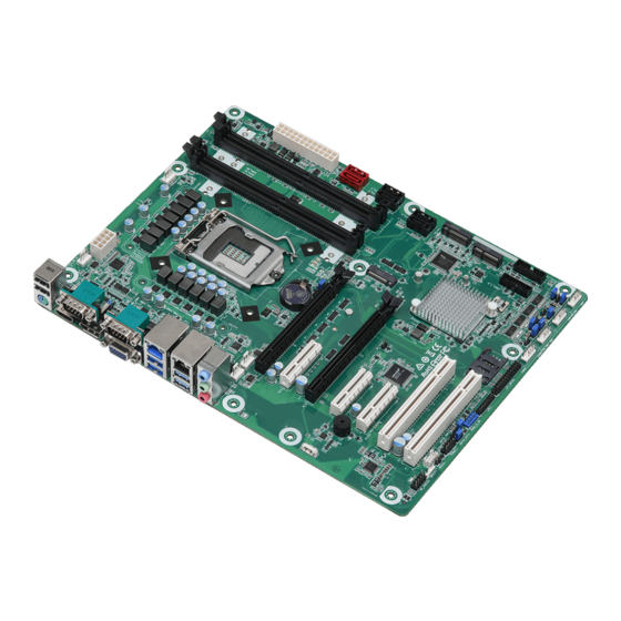
- Page 1 IMB-M46 User’s Manual ATX Motherboard with 10th Gen Intel Core™ i9/i7/i5/i3 Processors ® and Intel ® Q470E Chipset Manual Rev.: Revision Date: June 22, 2022 Part Number: 50M-00080-1000...
- Page 2 Preface Copyright Copyright 2022 ADLINK Technology, Inc. This document contains proprietary information protected by copyright. All rights are reserved. No part of this manual may be reproduced by any mechanical, electronic, or other means in any form without prior written permission of the manufacturer.
- Page 3 IMB-M46 Revision History Revision Description Date Initial release 2022-06-22 Preface...
-
Page 4: Table Of Contents
Table of Contents Preface ..........................ii Table of Contents ......................iv List of Figures ........................vi List of Tables ........................vii Introduction ........................ 1 Packing List ......................1 Optional Accessories ....................1 Specifications ......................3 Core System ......................3 I/O Interface ......................3 Video ........................ -
Page 5: Preface
IMB-M46 UEFI Setup ....................... 31 Menu Structure ....................... 31 Main Menu ......................32 Advanced Menu ...................... 33 Hardware Health Event Monitoring Screen ............. 42 Security Screen ....................... 43 Boot Screen ......................44 Safety Instructions ......................45 Getting Service ......................... 46... -
Page 6: List Of Figures
List of Figures Figure 1: Functional Block Diagram ......................5 Figure 2: IO Panel Connector Locations ....................7 Figure 3: Onboard Connector Locations ....................8 Figure 4: Mechanical Dimensions ......................10 Figure 5: Mechanical Dimensions - IO Panel ..................10 Preface... - Page 7 IMB-M46 List of Tables Table 1: IO Panel Connector Definitions ....................7 Table 2: Onboard Connector Definitions ....................8 Table 3: System Memory Map .......................25 Table 4: IO Map ............................25 Table 5: IRQ Lines PIC Mode ........................27 Table 6 IRQ Lines APIC Mode .......................27 Table 7 PCI Configuration Space Map ....................28...
- Page 8 This page intentionally left blank. viii Preface...
-
Page 9: Introduction
IMB-M46 1 Introduction ADLINK IMB-M46 ATX is an industrial motherboard supporting 10th Generation Intel® Core™ i9/i7/i5/i3 desktop processors, an Intel® Q470E Chipset, and 5 PCIe expansion slots to provide a cost-competitive embedded computing solution. It includes high-speed data transfer interfaces such as PCIe 3.0, USB 3.2 Gen2, and SATA 6 Gb/s (SATA III), and dual-channel DDR4 2400/2666/2933 MHz RAM for industrial automation applications. - Page 10 This page intentionally left blank. Introduction...
-
Page 11: Specifications
IMB-M46 2 Specifications Core System CPU: Intel® Core™ i9-10900E, 4.7GHz, 10 Core, 20M Cache, DDR4 2933MHz support, 65W • • Intel® Core™ i9-10900TE, 4.5GHz, 10 Core, 20M Cache, DDR4 2933MHz support, 35W • Intel® Core™ i7-10700E, 4.5GHz, 8 Core, 16M Cache, DDR4 2933MHz support, 65W •... -
Page 12: Video
Parallel Port: 1x LPT pin header PS/2 Combo Port: 1x PS/2 keyboard/mouse pin header DIO: 8-bit GPIO (shared with LPT header) TPM: TPM 2.0 M.2 connectors: • 1x M.2 (Key E, 2230) with PCIe x1, USB 2.0 and CNVi for Wireless 1x M.2 (Key B, 3042/3052) with PCIe x1 / USB 3.2 Gen1 / USB 2.0 and SIM socket for 4G/5G •... -
Page 13: Functional Block Diagram
IMB-M46 2.11 Functional Block Diagram Figure 1: Functional Block Diagram M.2 (Key M, 2242 / 2260 / 2280) with PCIe x4 and SATA3 shares the same source with SATA3_5 and • SATA3_6 Ports • When using M.2 PCIe x4 SSD, both SATA3_5 and SATA_6 Ports are disabled. - Page 14 This page intentionally left blank. Specifications...
-
Page 15: Mechanical Layout
IMB-M46 3 Mechanical Layout Connector Locations Figure 2: IO Panel Connector Locations Table 1: IO Panel Connector Definitions IO Panel Connectors Item Description 2x USB2.0 port PS/2 Keyboard/Mouse port COM1 RS-232/422/485 HDMI port DisplayPort COM2 RS-232/422/485 VGA port LAN1 2x USB 3.2 Gen 2 LAN2 2x USB 3.2 Gen 2... -
Page 16: Figure 3: Onboard Connector Locations
AF AE Figure 3: Onboard Connector Locations Table 2: Onboard Connector Definitions Onboard Connectors Item Description Remarks ATX 12V Power connector ATX12V1 ATX Power 24-pin SATA3 connectors SATA3_5, SATA3_6 SATA3 connectors SATA3_3, SATA3_4 SATA3 connectors SATA3_1, SATA3_2 M.2 Key-M socket M2_1 M.2 Key-B socket M2_B1... - Page 17 IMB-M46 Onboard Connectors Printer port / GPIO header LPT_GPIO1 LPC header LPT1 USB 2.0 header USB2_9, USB2_10 System Panel header PANEL1 Buzzer BUZZ1 SMBUS SMBUS_TEST1 SPDIF header Front Panel Audio header HDAUDIO_1 MCU connector MCU_CON1 Clear CMOS header CLRMOS1 PWR_BAT1...
-
Page 18: Mechanical Dimensions
Mechanical Dimensions Top View Dimensions: mm Figure 4: Mechanical Dimensions Side View Dimensions: mm Figure 5: Mechanical Dimensions - IO Panel Mechanical Layout... -
Page 19: Connector Pinouts
IMB-M46 4 Connector Pinouts See 3.1 Connector Locations on page 7 for connector locations. Rear IO Connectors 4.1.1 HDMI Signal Signal HDMI1_CON_DP2 HDMI1_CON_DN2 HDMI1_CON_DP1 HDMI1_CON_DN1 HDMI1_CON_DP0 HDMI1_CON_DN0 HDMI1_CON_CKP HDMI1_CON_CKN HDMI1_DDC_CLK HDMI1_DDC_DATA +5V_HDMI HDMI1_CON_HPD 4.1.2 DisplayPort Signal Signal CN_DDPx0+ CN_DDPx0- CN_DDPx1+... - Page 20 4.1.3 VGA Connector Signal Signal VGA_CON_RED VGA_CON_GREEN VGA_CON_BLUE +5V_HDMI VGA_DDCDAT VGA_CON_HS VGA_CON_VS VGA_DDCCLK 4.1.4 COM 1-2 Connector Stack (Top connector COM1, Bottom connector COM2) Signal RS-232 RS-422 RS-485 DCD# Tx/Rx- Tx/Rx+ DTR# DSR# RTS# CTS# No Power/ 5V/12V Connector Pinouts...
- Page 21 IMB-M46 4.1.5 Ethernet Connectors (LAN1, LAN2) Dual 10/100/1000Mbit/s LAN Ethernet controllers based on Intel® i219LM/i225LM, support PXE and WOL over both LANs.In BIOS menu only LAN 1 have wake on LAN option 10BASE- 1000BASE-T T/100BASE-TX LAN_MDI0+ LAN_MDI0- LAN_MDI1+ LAN_MDI2+ LAN_MDI2-...
-
Page 22: Onboard Headers / Connectors
Onboard Headers / Connectors 4.2.1 CPU_FAN1, SYS_FAN1, SYS_FAN2 Signal Description Ground +12 V FAN Power Tach FAN Tachometer FAN PWM The fan header supports +12 V at 1 A maximum 4.2.2 Chassis Fan Connectors (+12V) 4.2.3 System Panel Header 4.2.4 COM3, COM4, COM5, COM6 4.2.5 SATA1, SATA2, SATA3, SATA4, SATA5, SATA6... - Page 23 IMB-M46 4.2.6 USB Connectors USB 2.0 Header USB 3.2 Gen 1 Headers 4.2.7 Front Panel Audio Header 4.2.8 ATXPWR1 Signal Signal +3.3 V +3.3 V +3.3 V -12 V Ground Ground +5 V PS-ON# (power supply remote on/off) Ground Ground...
- Page 24 Signal Signal +12 V +5 V +12 V +5 V 3.3V Ground 4.2.9 ATX12V1 Signal Signal Ground +12V Ground +12V Ground +12V Ground +12V 4.2.10 Printer Port / GPIO Header Printer Port GPIO 4.2.11 LPC Header This connector supports a Trusted Platform Module (TPM) system, which can securely store keys, digital certificates, passwords, and data.
- Page 25 IMB-M46 4.2.12 SPDIF Header SPDIF header provides SPDIF audio output to HDMI VGA card and allows the system to connect with HDMI Digital TV / projector / LCD devices. Connect the SPDIF connector of an HDMI VGA card to this header.
-
Page 26: Jumper And Swtich Settings
Jumper and Swtich Settings 4.3.1 Clear CMOS Jumpers CLRMOS1 allows you to clear the data in CMOS. To clear and reset the system parameters back to factory default, turn off and unplug your system from power, wait for 15 seconds, and use a jumper cap to short pin2 and pin3 on CLRMOS1 for 5 seconds. -
Page 27: Expansion Slots
IMB-M46 4.3.6 Chassis Intrusion Headers 4.3.7 Digital Input / Output Default Value Setting 4.3.8 PWR_BAT1 4.3.9 PCIe Isolation Jumper 4.3.10 DACC1 Note: ACC function is used to auto clear CMOS when the system boots improperly.. Expansion Slots There are 5 PCI Express slots, 2 PCI slots, 3 M.2 sockets and 1 SIM socket on this motherboard. - Page 28 M.2 sockets: M.2 Key-M (M2_1) • M.2 Key-E (M2_2) • Connector Pinouts...
- Page 29 IMB-M46 • M.2 Key-B (M2_B1) Connector Pinouts...
- Page 30 This page intentionally left blank. Connector Pinouts...
-
Page 31: Driver Installation
IMB-M46 5 Driver Installation Download the requisite drivers for your system from the IMB-M46 product page at: https://www.adlinktech.com/Products/Industrial_Motherboards_SBCs/ATXMotherboards/IMB-M46 Driver Installation... - Page 32 This page intentionally left blank. Driver Installation...
-
Page 33: System Resources
IMB-M46 6 System Resources System Memory Map Table 3: System Memory Map Address Range Address Range Size Description (4GB-2MB) FFE00000 – FFFFFFFF 2 MB High BIOS Area (4GB-18MB) – (4GB-17MB-1) FEE00000 – FEEFFFFF 1 MB MSI Interrupts (4GB-20MB) – (4GB-19MB-1) FEC00000 –... - Page 34 Hex Range Device 0063-0063 Motherboard resources 0065-0065 Motherboard resources 0067-0067 Motherboard resources 0070-0070 Motherboard resources 0080-0080 Motherboard resources 0092-0092 Motherboard resources 00B2-00B3 Motherboard resources 0680-069F Motherboard resources FFFF-FFFF Motherboard resources 1800-18FE Motherboard resources 164E-164F Motherboard resources 0040-0043 System timer 0050-0053 System timer 0070-0077 System CMOS/real time clock...
-
Page 35: Interrupt Request (Irq) Lines
IMB-M46 Interrupt Request (IRQ) Lines 6.3.1 IRQ Lines PIC Mode Table 5: IRQ Lines PIC Mode IRQ# Device System timer COM2 COM1 COM3, COM4 System CMOS/real time clock COM5, COM6 Numeric data processor Intel Serial IO GPIO Host Controller Intel Chipset Smbus HD Audio Controller Note: These IRQs can be used for PCI devices when onboard device is disabled. -
Page 36: Pci Features
PCI Features 6.4.1 PCI Configuration Space Map Table 7 PCI Configuration Space Map Device Function Routing Description Number Number Number Intel Host Bridge Internal Intel VGA Controller Internal Intel USB 3.0 XHCI Internal Intel Data acquisition/signal process Internal Intel Communication device Internal Intel AHCI 1.0 controller Internal... -
Page 37: Smbus Slave Addresses
IMB-M46 Table 8 PCI Interrupt Routing Map LpcBridge High SMBus PCIE Root PCIE Root Port PCIE Root Line Definition Port #2 #3 (LAN3) Port #4 Audio (IT8892) (LAN4) Int0 INTA:16 INTA:16 INTA:16 INTB:17 INTC:18 INTD:19 Int1 INTB:17 INTC:18 INTD:19 INTA:16... - Page 38 This page intentionally left blank. System Resources...
-
Page 39: Uefi Setup
IMB-M46 7 UEFI Setup Menu Structure This section presents the primary menus of the UEFI Setup Utility. Use the following table as a quick reference for the contents of the UEFI Setup Utility. The subsections describe the submenus and options for each menu item. -
Page 40: Main Menu
7.2 Main Menu Upon entering the UEFI Setup Utility, the Main Menu is displayed, providing read-only information about your system and also allows you to set the System Date and Time. Refer to the screenshots and tables below for details of the submenus and settings. -
Page 41: Advanced Menu
IMB-M46 Advanced Menu Contains the configurations for the following: CPU Configuration, Chipset Configuration, Storage Configuration, Super IO Configuration, AMT Configuration, ACPI Configuration, USB Configuration, and Trusted Computing. Feature Description Instant Flash Updates system UEFI without requiring to enter operation systems. - Page 42 7.3.1 Advanced > CPU Configuration Feature Description Intel Hyper Threading Technology Allows multiple threads to run on each core, thereby improving the overall performance on threaded software Active Processor Cores Selects the number of cores to enable in each processor package CPU C States Support Optimizes power saving.
- Page 43 IMB-M46 7.3.2 Advanced > Chipset Configuration Feature Description Primary Graphics Adapter Switches the boot priority of your graphic adapter between PCI Express and Onboard Above 4G Decoding Enables 64-bit capable devices to be decoded in Above 4G Address Space VT-d Enables Intel®...
- Page 44 7.3.3 Advanced > Storage Configuration Feature Description SATA Controller(s) Enables the SATA Controller feature SATA Mode Selection Selects SATA mode SATA Aggressive Link Power Configures SATA Aggressive Link Power Management Management Hard Disk S.M.A.R.T. Enables the Self-Monitoring, Analysis, and Reporting Technology feature UEFI Setup...
- Page 45 IMB-M46 7.3.4 Advanced > Super IO Configuration Feature Description COM (1-6) Sets the parameters of COM 1-6 Type Select Selects the port type: RS232, RS422, or RS485 (for COM 1,2) Parallel Port Enables the Parallel port Device Mode Selects the device mode according to your connected device...
- Page 46 7.3.5 Advanced > AMT Technology Feature Description AMT BIOS Features Enables Intel® Active Management Technology BIOS Extension ASF support Enables Alert Specification Format USB Provisioning of AMT Enables AMT USB Provisioning Secure Erase mode Changes Secure Erase module behavior: as explained below Simulated: Performs SE flow without erasing SSD ...
- Page 47 IMB-M46 Feature Description ASF Sensors Table Enables ASF Sensor Table Non-UI Mode Resolution Sets resolution for non-UI text mode UI Mode Resolution Sets resolution for UI text mode Graphics Mode Resolution Sets resolution for graphics mode 7.3.6 Advanced > ACPI Configuration...
- Page 48 7.3.7 Advanced > USB Configuration Feature Description Legacy USB Support Enables support for legacy USB devices: Enabled: Enables support for legacy USB UEFI Setup Only: USB devices can only be used under UEFI setup and Windows / Linux OS USB Power Control Controls USB power UEFI Setup...
- Page 49 IMB-M46 7.3.8 Advanced > Trusted Computing Feature Description Security Device Support Enables BIOS support for security devices UEFI Setup...
-
Page 50: Hardware Health Event Monitoring Screen
Hardware Health Event Monitoring Screen This screen allows you to monitor the status of your system and installed devices, such as CPU temperature, mothboard temeprature, CPU fan speed, chassis fan speed, and the ctritical voltage. Feature Description FAN Setting (CPU, CHA1,2,3) Sets the speed for CPU Fan1, Chassis Fan1, Chassis Fan2, Chassis Fan 3 Case Open Feature Enables case open detection feature... -
Page 51: Security Screen
IMB-M46 Security Screen The Security Screen lets you change or clear the supervisor / user passwords for the system. Feature Description Administrator Password Sets Administrator Password User Password Sets User Password Secure Boot Enables support for Secure Boot UEFI Setup... -
Page 52: Boot Screen
Boot Screen This section displays the avaialbe devices on your system for you to configure the boot priority and settings. Feature Description Boot From Onboard LAN Enables Boot From Onboard LAN feature Setup Prompt Timeout Displays the number of seconds to wait for setup activation key Bootup Num-Lock Enables automatically activation of the Numeric Lock upon boot-up Full Screen Logo... -
Page 53: Safety Instructions
IMB-M46 Safety Instructions Read and follow all instructions marked on the product and in the documentation before you operate your system. Retain all safety and operating instructions for future use. Please read these safety instructions carefully. • Please keep this User‘s Manual for later reference. -
Page 54: Getting Service
6450 Via Del Oro, San Jose, CA 95119-1208, USA Tel: +1-408-360-0200 Toll Free: +1-800-966-5200 (USA only) Fax: +1-408-600-1189 Email: info@adlinktech.com ADLINK Technology (China) Co., Ltd. Address: 300 Fang Chun Rd., Zhangjiang Hi-Tech Park, Pudong New Area Shanghai, 201203 China Tel: +86-21-5132-8988 Fax: +86-21-5132-3588 Email: market@adlinktech.com...
Need help?
Do you have a question about the IMB-M46 and is the answer not in the manual?
Questions and answers