
Related Manuals for ADLINK Technology IMB-M43


Summary of Contents for ADLINK Technology IMB-M43
- Page 1 IMB-M43 ® ATX Intel Core™ i7/i5/i3 Industrial Motherboard User’s Manual Manual Rev.: 2.00 Revision Date: Dec. 31, 2015 Part No: 50-1X014-1000 Advance Technologies; Automate the World.
-
Page 2: Revision History
Revision History Revision Release Date Description of Change(s) 2.00 Dec. 31, 2015 Initial Release... -
Page 3: Preface
IMB-M43 Preface Copyright 2015 ADLINK Technology, Inc. This document contains proprietary information protected by copy- right. All rights are reserved. No part of this manual may be repro- duced by any mechanical, electronic, or other means in any form without prior written permission of the manufacturer. - Page 4 Conventions Take note of the following conventions used throughout this manual to make sure that users perform certain tasks and instructions properly. Additional information, aids, and tips that help users perform tasks. NOTE: NOTE: Information to prevent minor physical injury, component dam- age, data loss, and/or program corruption when trying to com- plete a task.
-
Page 5: Table Of Contents
IMB-M43 Table of Contents Revision History..............ii Preface ..................iii List of Figures ................ ix List of Tables................xi 1 Introduction ................ 1 Features................1 Specifications............... 2 Motherboard Topography ............ 5 I/O Panel................7 Onboard Headers and Connectors........9 1.5.1 CN46 24-pin ATX Power Input Connector.... - Page 6 2 Getting Started ..............23 Package Contents.............. 23 Mounting the motherboard..........24 Installing Memory Modules (DIMM) ........24 Installing Expansion Cards (PCI and PCI Express) ... 26 Jumper Settings ..............27 Driver Installation ............... 29 A Appendix: UEFI Setup Utility ..........31 Introduction ................
- Page 7 IMB-M43 Security................66 A.6.1 Administrator Password..........66 A.6.2 Secure Boot menu............ 67 Boot ................... 68 Save & Exit ................ 70 Important Safety Instructions ..........73 Getting Service..............75 Table of Contents...
- Page 8 This page intentionally left blank. viii Table of Contents...
-
Page 9: List Of Figures
IMB-M43 List of Figures Figure 1-1: IMB-M43 Motherboard............. 5 Figure 1-2: IMB-M43 I/O Panel ............7 Figure 1-3: LAN Port LED Indicators..........8 List of Figures... - Page 10 This page intentionally left blank. List of Figures...
-
Page 11: List Of Tables
IMB-M43 List of Tables Table 1-1: IMB-M43 Motherboard Legend........6 Table 1-2: IMB-M43 I/O Legend ............7 Table 1-3: COM Port Pin Definitions..........8 Table 1-4: LAN Port LED Legend ............. 8 Table A-1: Navigation Key Functions ..........32 List of Tables... - Page 12 This page intentionally left blank. List of Tables...
-
Page 13: Introduction
IMB-M43 Introduction With specification and BIOS updates, the content of this man- ual is subject to change without notice. Updated versions, as well as the latest CPU support lists are available at NOTE: NOTE: http://www.adlinktech.com For technical support, please visit http://askanexpert.adlink- tech.com/AAE/Answers.aspx for model-specific information. -
Page 14: Specifications
1.2 Specifications Processor& System Intel® Core™ i7-6700, 3.4GHz, 8M Cache, 14nm, 65W TDP, LGA1151 (4C/8T) Intel® Core™ i7-6700TE, 2.4GHz 8M Cache, 14nm, 35W TDP, LGA1151 (4C/8T) Intel® Core™ i5-6500, 3.2GHz, 6M Cache, 14nm, 65W TDP, LGA1151 (4C/4T) Intel® Core™ i5-6500TE, 2.3GHz, 6M Cache, 14nm, 35W TDP, LGA1151 (4C/4T) Intel®... - Page 15 IMB-M43 Microsoft® Windows® 7 32/64-bit Microsoft® Windows® 8.1 64-bit Microsoft® Windows® 10 64-bit Ubuntu 15.10 32/64-bit 6x SATA 6.0 Gb/s connectors Serial ATA Software RAID support 0/1/5/10 6x USB 3.0 connector (rear) 2x USB 3.0 pin header 4x USB2.0 pin headers 2x USB2.0 vertical type A connector...
- Page 16 1x 10-pin/2.54mm GPIO pin header: 4 in and 4 out, one DI/O ground pin and one power pin (5V/12V/no power, jumper selected) Audio Audio Codec Realtek® ALC262-VC2-GR Interface 1x Mic-in, 1x Line-out and 1x Line-in connector (rear) Graphics Graphics Engine Integrated Intel® HD graphics series (based on CPU) 1 VGA connector (rear), resolution up to 1920 x 1200@60Hz 2 DP connector (rear), resolution up to 4096x2304 @...
-
Page 17: Motherboard Topography
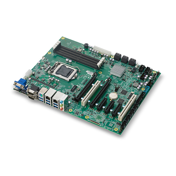
IMB-M43 1.3 Motherboard Topography Figure 1-1: IMB-M43 Motherboard FAN2 4-pin system FAN1 connector FAN1 4-pin CPU FAN connector Upper: SATA3 SATA3/4 Lower: SATA4 Upper: SATA1 SATA1/2 Lower: SATA2 Upper: SATA5 SATA5/6 Lower: SATA6 FAN3 4-pin system FAN2 connector CN23 Digital I/O pin header... -
Page 18: Table 1-1: Imb-M43 Motherboard Legend
PCIe x16 connector AA CN31 Serial port 3 power select BB CN32 Serial port 4 power select CC CN35 Serial port 5 power select DD CN36 Serial port 6 power select CN24 Clear CMOS header Table 1-1: IMB-M43 Motherboard Legend Introduction... -
Page 19: I/O Panel
COM2 Line Out Mic In USB3.0 (#3) USB2.0(#3) Table 1-2: IMB-M43 I/O Legend The IMB-M43 supports RS232/422/485 on COM ports 1 and 2, with pin definitions as follows, with both COM ports configurable in BIOS setup. RS232 RS422 RS485 DCD, Data Carrier Detect... -
Page 20: Table 1-3: Com Port Pin Definitions
RS232 RS422 RS485 DTR, Data Terminal Ready DSR, Data Set Ready RTS, Request To Send CTS, Clear To Send RI, Ring Pin Table 1-3: COM Port Pin Definitions Two LEDs on either side of the RJ-45 LAN port indicate activity and speed as follows. -
Page 21: Onboard Headers And Connectors
IMB-M43 1.5 Onboard Headers and Connectors Placing jumper covers over headers and connectors may cause permanent damage. CAUTION: 1.5.1 CN46 24-pin ATX Power Input Connector Name P_+3V3_PSU P_+3V3_PSU P_+5V_PSU P_+5V_PSU PSU_PWROK P_+5VSB_PSU P_+12V_PSU_CN P_+12V_PSU_CN P_+3V3_PSU P_+3V3_PSU P_N12V_PSU PS_ON-L PS_TP1 (Test pad) -
Page 22: Cn44 System Panel Header
1.5.2 CN44 System Panel Header Name CN_HDLED+ CN_PLED+ CN_HDLED- CN_PLED- CN_PWRBTN-L CN_RESETBTN-L 1.5.3 COM3 Serial Port Header Name CN_COM-C_DCD-L Introduction... -
Page 23: Com4 Serial Port Header
IMB-M43 Name CN_COM-C_DSR-L CN_COM-C_RX CN_COM-C_RTS-L CN_COM-C_TX CN_COM-C_CTS-L CN_COM-C_DTR-L CN_COM-C_POWER 1.5.4 COM4 Serial Port Header Name CN_COM-D_DCD-L CN_COM-D_DSR-L CN_COM-D_RX CN_COM-D_RTS-L CN_COM-D_TX CN_COM-D_CTS-L CN_COM-D_DTR-L CN_COM-D_POWER Introduction... -
Page 24: Com5 Serial Port Header
1.5.5 COM5 Serial Port Header Name CN_COM-E_DCD-L CN_COM-E_DSR-L CN_COM-E_RX CN_COM-E_RTS-L CN_COM-E_TX CN_COM-E_CTS-L CN_COM-E_DTR-L CN_COM-E_POWER 1.5.6 COM6 Serial Port Header Name CN_COM-F_DCD-L Introduction... -
Page 25: Cn16 Usb3.0 Header
IMB-M43 Name CN_COM-F_DSR-L CN_COM-F_RX CN_COM-F_RTS-L CN_COM-F_TX CN_COM-F_CTS-L CN_COM-F_DTR-L CN_COM-F_POWER 1.5.7 CN16 USB3.0 Header Pin Name P_+5V_USB_VBUS_P9 CN_U3_USB3_RXN_7 CN_U3_USB3_RXP_7 Introduction... -
Page 26: Cn14 Usb2.0 Header
Pin Name CN_U3_USB3_TXN_7 CN_U3_USB3_TXP_7 CN_U2_USB2N_5 CN_U2_USB2P_5 CN_U2_USB2P_6 CN_U2_USB2N_6 CN_U3_USB3_TXP_8 CN_U3_USB3_TXN_8 CN_U3_USB3_RXP_8 CN_U3_USB3_RXN_8 P_+5V_USB_VBUS_P10 1.5.8 CN14 USB2.0 Header Name P_+5V_USB_VBUS_P6 P_+5V_USB_VBUS_P5 CN_U2_USB2N_7 CN_U2_USB2N_8 CN_U2_USB2P_7 Introduction... -
Page 27: Cn15 Usb2.0 Header
IMB-M43 Name CN_U2_USB2P_8 1.5.9 CN15 USB2.0 Header Name P_+5V_USB_VBUS_P7 P_+5V_USB_VBUS_P8 CN_U2_USB2N_9 CN_U2_USB2N_10 CN_U2_USB2P_9 CN_U2_USB2P_10 1.5.10 CN38 Front Audio Header Introduction... - Page 28 Name A_MIC2_IN_L GND_AUD A_MIC2_IN_R CN_FP_PRES-L A_L_OUT2_R CN_SRTN1 A_HP2_JD A_L_OUT2_L CN_SRTN2 Introduction...
-
Page 29: Fan1 4-Pin Cpu Fan Connector
IMB-M43 1.5.11 FAN1 4-Pin CPU FAN Connector Name Note P_+12V_PSU FAN-Power O_CPUFAN_IN/ FAN-TACHO BMC_FAN_IN_CPU O_CPUFAN_OUT/ FAN-PWM IN BMC_FAN_OUT_CPU 1.5.12 FAN2 4-Pin System FAN1 Connector Name Note P_+12V_PSU FAN-Power O_SYSFAN_IN0/ FAN-TACHO BMC_FAN_IN O_SYSFAN_OUT0/ FAN-PWM IN BMC_FAN_OUT Introduction... -
Page 30: Fan3 4-Pin System Fan2 Connector
1.5.13 FAN3 4-Pin System FAN2 Connector Name Note P_+12V_PSU FAN-Power O_SYSFAN_IN1/ FAN-TACHO BMC_FAN_IN1 O_SYSFAN_OUT1/ FAN-PWM IN BMC_FAN_OUT1 1.5.14 CN54 LAN1 LED Indicator LAN1 Link with Activity LED Header P_+3V3_LAN_A L_i219_LED0_LINK/ACT-L Introduction... -
Page 31: Cn53 Lan2 Led Indicator
IMB-M43 1.5.15 CN53 LAN2 LED Indicator LAN1 Link with Activity LED Header P_+3V3_LAN_A L_i210_LED1_LINK/ACT-L 1.5.16 PS2 Combo Connector Name Note O_KBDATA O_MSDATA Introduction... -
Page 32: Cn37 Lpt Connector
Name Note P_+PS2 Power source from P_+5V_DUAL O_KBCLK O_MSCLK 1.5.17 CN37 LPT Connector Name O_STB-L_CON O_AFD-L_CON O_PD0_CON O_ERR-L_CON O_PD1_CON O_INIT-L_CON O_PD2_CON O_SLIN-L_CON O_PD3_CON O_PD4_CON O_PD5_CON O_PD6_CON O_PD7_CON O_ACK-L_CON Introduction... - Page 33 IMB-M43 Name O_BUSY_CON O_PE_CON O_SLCT_CON Introduction...
- Page 34 Introduction...
-
Page 35: Getting Started
Obtain authorization from the dealer before returning any product to ADLINK. IMB-M43 ATX industrial motherboard I/O shield The IMB-M43 must be protected from static dis- charge and physical shock. Never remove any of the socketed parts except at a static-free work- WARNING: station. -
Page 36: Mounting The Motherboard
Avoid over-tightening screws to prevent PCB damage. CAUTION: 2.3 Installing Memory Modules (DIMM) The IMB-M43 provides four 288-pin DDR4 DIMM slots supporting Dual Channel Memory technology. Dual channel configuration requires installation of DDR4 DIMM pairs of identical brand, speed, size, and chip type. - Page 37 IMB-M43 2. Press the slot’s retaining clips outward to unlock. 3. Align the memory module on the socket, making sure that the module notch matches the slot rail. 4. Insert the module firmly into the slot until the retaining clips snap back inwards and the module is securely seated.
-
Page 38: Installing Expansion Cards (Pci And Pci Express)
2.4 Installing Expansion Cards (PCI and PCI Express) The IMB-M43 provides: 2x PCI slots receiving expansion cards with 32-bit PCI inter- face. If PEG3 is occupied, PEG1 is PCIex8 Gen3, PEG2 is PCIex4 Gen3, and PEG3 is PCIex4 Gen3. If PEG3 is not occupied and PEG2 is occupied, PEG1 is PCIex8 Gen3, PEG2 is PCIex8 Gen3, and PEG3 is no sig- nal. -
Page 39: Jumper Settings
IMB-M43 Before installing expansion cards, ensure the power supply is switched off or disconnected. Check the card's documentation and perform requisite system configurations before installation. 1. Remove the system unit cover (if the motherboard is installed in a chassis). 2. Remove the bracket facing the destination slot. - Page 40 CN25 Clear ME *1-2 Normal Clear ME CN22 GPIO Port Power Select *N/A No Power P_+5V_PSU P_+12V_PSU CN31 Serial Port 3 Power Select *N/A No Power P_+5V_PSU P_+12V_PSU CN32 Serial Port 4 Power Select *N/A No Power P_+5V_PSU P_+12V_PSU CN35 Serial Port 5 Power Select *N/A No Power...
-
Page 41: Driver Installation
IMB-M43 CN36 Serial Port 6 Power Select *N/A No Power P_+5V_PSU P_+12V_PSU 2.6 Driver Installation Download requisite drivers your system from http://www.adlinktech.com and install. Getting Started... - Page 42 This page intentionally left blank. Getting Started...
-
Page 43: A Appendix: Uefi Setup Utility
IMB-M43 Appendix A - UEFI Setup Utility A.1 Introduction This section explains how to use the UEFI Setup Utility to config- ure your system. The UEFI chip on the motherboard stores the UEFI Setup Utility. Select <Del> during the Power-On-Self-Test (POST) to enter the UEFI Setup Utility, otherwise, POST will con- tinue with its test routines. -
Page 44: Navigation Keys
A.3 Navigation Keys Key(s) Function R/L Arrow Moves cursor left or right to select Menus U/D Arrow Moves cursor up or down to select items Changes option for the selected item Enter Opens the selected Menu Displays General Help Previous values Optimized default values for all settings Saves changes and exits Setup Opens the Exit Menu or exits the current screen... -
Page 45: Advanced Menu
IMB-M43 A.5 Advanced Menu UEFI Setup Utility... -
Page 46: Acpi Settings
A.5.1 ACPI Settings Enable Hibernation Enables or Disables System ability to hibernate (OS/S4 Sleep State). This option may be not effective with some OS. ACPI Sleep State Selects the highest ACPI sleep state the system will enter when the SUSPEND button is pressed. UEFI Setup Utility... -
Page 47: Cpu Configuration
IMB-M43 A.5.2 CPU Configuration UEFI Setup Utility... - Page 48 Hyper-threading Enabled for Windows XP and Linux optimized for HT-technology and Disabled for other OS not optimized for HT Technology. When Disabled only one thread per enabled core is enabled. Active Processor Cores Number of cores to enable in each processor package. Intel Virtualization Technology When enabled, utilizes the additional hardware capabilities pro- vided by Vanderpool Technology...
- Page 49 IMB-M43 Intel Speed Shift Technology Enables/disables Intel® Speed Shift Technology support. Enabling will expose the CPPC v2 interface to allow for hardware controlled P-states. (tm) Intel® SpeedStep Allows more than two frequency ranges to be supported. Turbo Mode Turbo Mode.
-
Page 50: Chipset Configuration
ACPI 3.0 T-States Enables/disables ACPI 3.0 T-States. Intel TXT(LT) Support Disables Intel® TXT(LT) support. A.5.3 Chipset Configuration Memory Remap Enables/disables Memory Remap above 4GB. UEFI Setup Utility... -
Page 51: System Agent (Sa) Configuration
IMB-M43 A.5.4 System Agent (SA) Configuration VT-d VT-d capability Above 4GB MMIO BIOS assignment Enables/disables above 4GB MemoryMapped IO BIOS assign- ment. This is disabled automatically when Aperture Size is set to 2048MB. UEFI Setup Utility... -
Page 52: Graphics Configuration
A.5.5 Graphics Configuration Primary Display Selects which IGFX/PEG/PCI Graphics device should be Primary Display Or selects SG for Switchable Gfx. Internal Graphics Keep IGFX enabled based on the setup options. GTT Size Selects the GTT Size UEFI Setup Utility... -
Page 53: Pci Express Configuration
IMB-M43 Aperture Size Selects the Aperture Size Above 4GB MMIO BIOS assignment is automatically enabled when selecting 2048MB aperture. To use this feature, please disable CSM Support. NOTE: NOTE: DVMT Pre-Allocated Selects DVMT 5.0 Pre-Allocated (Fixed) Graphics Memory size used by the Internal Graphics Device. - Page 54 PEG Port Configuration PEG Port Options Max Link Speed Configure PEG1 Max Speed Option: Auto, Gen1, Gen2, Gen3 Max Link Speed Configure PEG2 Max Speed Option: Auto, Gen1, Gen2, Gen3 Max Link Speed Configure PEG3 Max Speed Option: Auto, Gen1, Gen2, Gen3 UEFI Setup Utility...
- Page 55 IMB-M43 PCIE1 PCIe Speed Selects PCI Express port speed. Options: Auto, Gen1, Gen2, Gen3 Detect Non-Compliance Device Options: Disabled/Enabled Detects Non-Compliance PCI Express Device. If enabled, increases POST time. UEFI Setup Utility...
- Page 56 PCIE2 PCIe Speed Selects PCI Express port speed. Options: Auto, Gen1, Gen2, Gen3 Detect Non-Compliance Device Options: Disabled/Enabled Detects Non-Compliance PCI Express Device. If enabled, increases POST time. UEFI Setup Utility...
-
Page 57: Usb Configuration
IMB-M43 A.5.7 USB Configuration UEFI Setup Utility... - Page 58 USB Precondition Precondition work on USB host controller and root ports for faster enumeration. USB3 Port 1 – USB3 Port 8 Enables/disables USB port. USB2 Port 1 – USB2 Port 14 Enables/disables USB port. Legacy USB Support Enables Legacy USB support. AUTO option disables legacy support if no USB devices are con- nected.
- Page 59 IMB-M43 DISABLE option will keep USB devices available only for EFI applications. XHCI Hand-off This is a workaround for OSes without XHCI hand-off support. The XHCI ownership change should be claimed by the XHCI driver. USB Mass Storage Driver Support Enables/disables USB Mass Storage Driver Support.
-
Page 60: Usb Configuration
A.5.8 USB Configuration USB Controller Enables/disables the USB controller. Intel USB 3.0 Mode Enables/disables Intel USB 3.0 mode. Legacy USB Support Selects legacy support for USB devices, from default Enabled, supporting legacy USB, Auto, supporting legacy USB when devices are connected, and Disabled (if USB compatibility issues occur, it is recommended to select Disabled to enter OS), and UEFI Setup Only, in which USB devices are allowed only under UEFI setup and Windows/Linux OS. -
Page 61: Hd Audio Configuration
IMB-M43 Legacy USB 3.0 Support Enables/disables legacy support for USB 3.0 devices, with default Enabled. A.5.9 HD Audio Configuration HD Audio Control Detection of the HD-Audio device. Disabled = HDA will be unconditionally disabled Enabled = HDA will be unconditionally enabled Auto = HDA will be enabled if present, disabled otherwise. -
Page 62: Sata Configuration
A.5.10 SATA Configuration SATA Configuration SATA Controller(s) Enables/disables SATA Device. SATA Mode Selection Determines how SATA controller(s) operate. Options: AHCI, RAID Aggressive LPM Support Enable PCH to aggressively enter link power state. SATA Controller Speed Indicates the maximum speed the SATA controller can support. Options: Default, Gen1, Gen2, Gen3 UEFI Setup Utility... -
Page 63: Onboard Device Configuration
IMB-M43 Port 1 – Port 6 Enables or Disables SATA Port A.5.11 Onboard Device Configuration UEFI Setup Utility... - Page 64 This page intentionally left blank. Serial Port 1 Enables or Disables Serial Port (COM) COM1 Control Selects COM1 mode. RS232, RS422 or RS485 Serial Port 2 Enables or Disables Serial Port (COM) COM2 Control Selects COM2 mode. RS232, RS422 or RS485 Serial Port 3 - 6 Enables or Disables Serial Port (COM) UEFI Setup Utility...
- Page 65 IMB-M43 Serial Port Console Redirection COM1 – COM6 and COM (PCI Bus0, Dev22, Func3) Console Redirection Enables or Disables Legacy Console Redirection Selects a COM Port to display redirection of Legacy OS and Leg- acy OPROM messages Options: COM1 – COM6 and COM (PCI Bus0, Dev22, Func3)
-
Page 66: Advance Power Management
A.5.12 Advance Power Management Power Supply Unit ATX: OS turns off system power when shut down. NOTE: AT mode will not support S3 & S4. State After G3 Specify what state to go to when power is re-applied after a power failure (G3 state). - Page 67 IMB-M43 Selects DynamicTime , System will wake on the current time + Increase minute(s) PCIe Slot Wake Enables/disables PCI Express Slot wake capability Onboard LAN i219 Wake Enables/disables onboard LAN wake capability PCI/SIO Wake Enables/disables PCI/SIO wake capability PS/2 Device Wake...
-
Page 68: Amt Configuration
A.5.13 AMT Configuration Intel AMT Enables/disables Intel® Active Management Technology BIOS Extension. Note: iAMT H/W is always enabled. This option just controls the BIOS extension execution. If enabled, this requires additional firm- ware in the SPI device BIOS Hotkey Pressed OEMFLag Bit 1: Enables/disables BIOS hotkey press. -
Page 69: Intel® Bios Guard Technology
IMB-M43 ® A.5.14 Intel BIOS Guard Technology Intel Bios Guard Support Enables/disables Intel BIOS Guard Support. Disable before flash- ing BIOS. UEFI Setup Utility... -
Page 70: Network Stack Configuration
A.5.15 Network Stack Configuration Network Stack Enables/disables UEFI Network Stack UEFI Setup Utility... -
Page 71: Csm Configuration
IMB-M43 A.5.16 CSM Configuration CSM Support Enables/disables CSM Support. GateA20 Active UPON REQUEST - GA20 can be disabled using BIOS services. ALWAYS - do not allow disabling GA20; this option is useful when any RT code is executed above 1MB. - Page 72 INT19 Trap Response BIOS reaction on INT19 trapping by Option ROM: IMMEDIATE - execute the trap right away; POSTPONED - execute the trap during legacy boot. Boot option filter This option controls Legacy/UEFI ROMs priority Network Controls the execution of UEFI and Legacy PXE OpROM Storage Controls the execution of UEFI and Legacy Storage OpROM Video...
-
Page 73: Nct6106D Hw Monitor
IMB-M43 A.5.17 NCT6106D HW Monitor UEFI Setup Utility... - Page 74 CPU Fan Control Mode CPU Fan Control Mode Select Options: Manual Mode, SMART FAN IV T1 (Temperature 1), Range: 1-100 T1 Duty Set T1 related DC/PWM value, Range: 0-255 T2 (Temperature 2), Range: 1-100 T2 Duty Set T2 related DC/PWM value, Range: 0-255 T3 (Temperature 3), Range: 1-100 UEFI Setup Utility...
- Page 75 IMB-M43 T3 Duty Set T3 related DC/PWM value, Range: 0-255 T4 (Temperature 4), Range: 1-100 T4 Duty Set T4 related DC/PWM value, Range: 0-255 Critical Critical Temperature System Fan1 Control Mode System Fan1 Control Mode Select Options: Manual Mode, SMART FAN IV...
- Page 76 Critical Critical Temperature System Fan2 Control Mode System Fan2 Control Mode Select Options: Manual Mode, SMART FAN IV T1 (Temperature 1), Range: 1-100 T1 Duty Set T1 related DC/PWM value, Range: 0-255 T2 (Temperature 2), Range: 1-100 T2 Duty Set T2 related DC/PWM value, Range: 0-255 T3 (Temperature 3), Range: 1-100 T3 Duty Set T3 related DC/PWM value, Range: 0-255...
-
Page 77: Miscellaneous Configuration
IMB-M43 A.5.18 Miscellaneous Configuration High Precision Timer Enables/disables the High Precision Event Timer. Port 80h Redirection Control where the Port 80h cycles are sent. Options: LPC Bus, PCIE Bus SMART Self Test Run SMART Self Test on all HDDs during POST. -
Page 78: Security
Range is 0.0% - 2.0%. A.6 Security A.6.1 Administrator Password Administrator Password Set Administrator Password User Password Set User Password RTC Lock Enable will lock bytes 38h-3Fh in the lower/upper 128-byte bank of RTC RAM. UEFI Setup Utility... -
Page 79: Secure Boot Menu
IMB-M43 BIOS Lock Enables/disables the PCH BIOS Lock Enable (BLE bit) feature. A.6.2 Secure Boot menu Secure Boot Secure Boot can be enabled if: 1. System running in User mode with enrolled Platform Key(PK) 2. CSM function is disabled Secure Boot Mode Secure Boot mode selector. -
Page 80: Boot
Key Management Enables experienced users to modify Secure Boot variables A.7 Boot Setup Prompt Timeout Number of seconds to wait for setup activation key. 65535(0xFFFF) means indefinite waiting. Bootup NumLock State Selects the keyboard NumLock state Quiet Boot Enables/disables Quiet Boot option UEFI Setup Utility... - Page 81 IMB-M43 Fast Boot Enables/disables boot with initialization of a minimal set of devices required to launch active boot option. Has no effect for BBS boot options. New Boot Option Policy Controls the placement of newly detected UEFI boot options Options: Default, Place First, Place Last...
-
Page 82: Save & Exit
A.8 Save & Exit Save Changes and Exit Exit system setup after saving the changes. Discard Changes and Exit Exit system setup without saving any changes. Save Changes and Reset Reset the system after saving the changes. Discard Changes and Reset Reset system setup without saving any changes. - Page 83 IMB-M43 Save Changes Save Changes done so far to any of the setup options. Discard Changes Discard Changes done so far to any of the setup options. Restore Defaults Restore/Load Default values for all the setup options. Save as User Defaults Save the changes done so far as User Defaults.
- Page 84 This page intentionally left blank. UEFI Setup Utility...
-
Page 85: Important Safety Instructions
IMB-M43 Important Safety Instructions For user safety, please read and follow all instructions, WARNINGS, CAUTIONS, and NOTES marked in this manual and on the associated equipment before handling/operating the equipment. Read these safety instructions carefully. Keep this user’s manual for future reference. - Page 86 Never attempt to fix the equipment. Equipment should only be serviced by qualified personnel. A Lithium-type battery may be provided for uninterrupted, backup or emergency power. Risk of explosion if battery is replaced with one of an incorrect type. Dispose of used batteries appropriately. WARNING: Equipment must be serviced by authorized technicians when:...
-
Page 87: Getting Service
San Jose, CA 95138, USA Tel: +1-408-360-0200 Toll Free: +1-800-966-5200 (USA only) Fax: +1-408-360-0222 Email: info@adlinktech.com ADLINK Technology (China) Co., Ltd. Address: (201203) 300 Fang Chun Rd., Zhangjiang Hi-Tech Park Pudong New Area, Shanghai, 201203 China Tel: +86-21-5132-8988 Fax: +86-21-5132-3588 Email: market@adlinktech.com... - Page 88 84 Genting Lane #07-02A, Cityneon Design Centre Singapore 349584 Tel: +65-6844-2261 Fax: +65-6844-2263 Email: singapore@adlinktech.com ADLINK Technology Singapore Pte. Ltd. (Indian Liaison Office) Address: #50-56, First Floor, Spearhead Towers Margosa Main Road (between 16th/17th Cross) Malleswaram, Bangalore - 560 055, India Tel: +91-80-65605817, +91-80-42246107 Fax:...
Need help?
Do you have a question about the IMB-M43 and is the answer not in the manual?
Questions and answers