Table of Contents
Advertisement
Quick Links
6EDL_SPI_LINK configuration dongle for
6EDL71x1 series
User guide
UM_2309_PL88_2311_023724
About this document
Scope and purpose
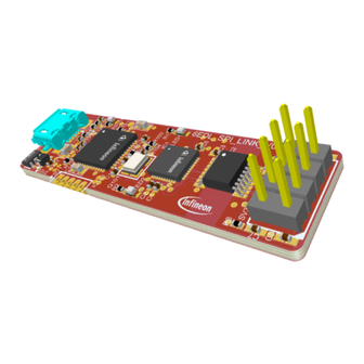
This user manual explains the purpose and use of the 6EDL_SPI_LINK configuration adapter bridge (or
"dongle"), which provides an interface from a PC USB output to a target board containing a 6EDL71x1 series
smart gate driver IC. This interface is used for reading and writing the configuration parameters via a PC-based
software application. A description of the 6EDL_SPI_LINK functionality, circuitry and firmware is provided with
instructions for connection and use.
Intended audience
This document is intended for design engineers, applications engineers, and technicians who use the 6EDL71x1
series gate driver.
Infineon components featured
XMC1402Q040X0032AAXUMA1
•
(32K x 8) flash in PG-VQFN-40package)
XMC4200Q48K256BAXUMA1
•
(256K x 8) flash in PG-VQFN-48 package)
TLS202B1MBV33HTSA1
•
package)
User guide
Please read the sections "Important notice" and "Warnings" at the end of this document
www.infineon.com
(XMC1000 32-bit, 48 MHz Arm® Cortex®-M0 microcontroller with 32 KB
(XMC4000 32-bit, 80 MHz Arm® Cortex®-M4 microcontroller with 256 KB
(linear voltage regulator, fixed 3.3 V positive output 150 mA in PG-SCT595-5
V 1.0
2023-11-02
Advertisement
Table of Contents

Related Manuals for Infineon 6EDL SPI LINK


Summary of Contents for Infineon 6EDL SPI LINK
-
Page 1: About This Document
Intended audience This document is intended for design engineers, applications engineers, and technicians who use the 6EDL71x1 series gate driver. Infineon components featured XMC1402Q040X0032AAXUMA1 (XMC1000 32-bit, 48 MHz Arm® Cortex®-M0 microcontroller with 32 KB •... -
Page 2: Table Of Contents
6EDL_SPI_LINK configuration dongle for 6EDL71x1 series User guide Table of contents Table of contents About this document ........................1 Table of contents ..........................2 Introduction .......................... 3 6EDL_SPI_LINK adapter .......................... 3 Additional items included ........................4 Specifications ........................5 Schematic ..........................6 Functional description ...................... -
Page 3: Introduction
This adapter works with a PC-based application called the MOTIX™ BPA Motor Control Workbench, which is a Windows-based graphical user interface (GUI) tool available to download from Infineon’s website. The configuration can be loaded into RAM during product development and optimization or into permanent memory using the one-time programmable (OTP) mode. -
Page 4: Additional Items Included
6EDL_SPI_LINK configuration dongle for 6EDL71x1 series User guide Introduction Additional items included Figure 3 USB Micro-B USB to male A cable (1 meter or 3 ft) cable Figure 4 Ribbon cable 8-way, 2-row, female-to-female (6 inch/150 mm) User guide V 1.0 2023-11-02... -
Page 5: Specifications
Output: 3.3 V or 5 V from target board, SPI clock, and data • Control scheme Debugger controller: XMC4200 series MCU with Segger J-Link firmware • 6EDL71x1 SPI encoder: XMC1400 series MCU with Infineon 6EDL_SPI_LINK firmware • Protection features Isolation interface •... -
Page 6: Schematic
6EDL_SPI_LINK configuration dongle for 6EDL71x1 series User guide Schematic Schematic C107 C102 C103 C104 C108 C105 C106 C109 C110 C201 Figure 5 6EDL_SPI_LINK schematic User guide V 1.0 2023-11-02... -
Page 7: Functional Description
6EDL_SPI_LINK configuration dongle for 6EDL71x1 series User guide Functional description Functional description The purpose of the 6EDL_SPI_LINK configuration adapter is to provide an interface between a PC running the MOTIX™ BPA Motor Control Workbench application and a target board carrying a 6EDL71x1 series smart motor control IC. - Page 8 6EDL_SPI_LINK configuration dongle for 6EDL71x1 series User guide Functional description Data sampling happens during the falling edge of the SPI clock signal. All communication packets are contained in a 24-bit shift register: 7-bit address • 16-bit data • 1-bit command •...
- Page 9 6. The master MCU interface is used to download the 6EDL_SPI_LINK firmware to the XMC1402 (IC1) from the PC via the DAVE™ IDE or Infineon XMC™ Flasher. This firmware is also factory installed but can be updated by the user if necessary.
-
Page 10: Instructions
6EDL_SPI_LINK configuration dongle for 6EDL71x1 series User guide Instructions Instructions 1. Install the Infineon Developer Center Launcher. 2. After installing the launcher, select the Manage Tools tab and locate the MOTIX™ BPA Motor Control Workbench to install on the PC. Figure 12 Download OTIX™... - Page 11 EVAL or REF board-specific project options available in the menu, which communicate with an XMC™ microcontroller located on the board. Infineon EVAL and REF board MCUs contain firmware that allows them to communicate directly with a 6EDL71x1 device via an onboard or external debugger for configuration and monitoring.
- Page 12 6EDL_SPI_LINK configuration dongle for 6EDL71x1 series User guide Instructions Figure 16 Connecting 6EDL_SPI_LINK If the following message appears, click SPI LINK to continue the connection. Figure 17 Parameter adjustment 8. Navigate to the Windows Device Manager and select the COM port connected to the 6EDL_SPI_LINK adapter as shown in Figure User guide...
- Page 13 6EDL_SPI_LINK configuration dongle for 6EDL71x1 series User guide Instructions Figure 18 Identifying the COM port User guide V 1.0 2023-11-02...
- Page 14 6EDL_SPI_LINK configuration dongle for 6EDL71x1 series User guide Instructions 9. Select the COM port from the drop-down menu as shown in Figure Figure 19 COM port selection 10. If the connection is successful, the Disconnected message changes to Connected, and the red color dot becomes green.
- Page 15 6EDL_SPI_LINK configuration dongle for 6EDL71x1 series User guide Instructions After the connection is successful, the Workbench software is ready to read and write configuration settings to the target 6EDL71x1 device. Attention: During the following operations, ensure that the target board is powered at all times. 11.
- Page 16 6EDL_SPI_LINK configuration dongle for 6EDL71x1 series User guide Instructions You can change the parameters individually. This is done in a similar way as shown in Figure However, instead of using the Write Parameters as shown in Figure 23, you can use the write button to modify the parameter block as shown in Figure Figure 24...
- Page 17 6EDL_SPI_LINK configuration dongle for 6EDL71x1 series User guide Instructions The following message is displayed when the data is transferred to the target device. Figure 27 Write message 14. The updated parameters can also be stored in a project file on the PC; click Project > Save As and choose an appropriate project name.
- Page 18 6EDL_SPI_LINK configuration dongle for 6EDL71x1 series User guide Instructions Figure 30 Parameter read from a target device 17. The user can read the individual parameter blocks using the read button of the parameter block as shown Figure Figure 31 Parameter read from target device The following message displays after a successful reading of the parameter block.
- Page 19 6EDL_SPI_LINK configuration dongle for 6EDL71x1 series User guide Instructions Figure 33 Monitoring the target device through the “Status” window Once the designer has finalized all of the configuration options and parameters, these values can be permanently burned into the 6EDL71x1 OTP memory using the Burn 6EDL71x1 as shown in Figure Figure 34 Programming the parameters into OTP memory...
-
Page 20: Firmware Update
The J-Link firmware is factory-installed and cannot be updated by the end user. The J-Link port should never be accessed by the end user! To install a firmware update, first install the XMCFlasher tool from the Infineon Developer Center Launcher. Note: It is necessary to have Java installed on the PC to run this application. - Page 21 6EDL_SPI_LINK configuration dongle for 6EDL71x1 series User guide Firmware update Figure 37 Selecting the XMC1402-0032 3. Select the firmware .HEX file by using the Select File.. as shown in Figure Figure 38 Loading the firmware .HEX file 4. Click Program to install the firmware. 5.
- Page 22 6EDL_SPI_LINK configuration dongle for 6EDL71x1 series User guide Firmware update Figure 39 Programming completed User guide V 1.0 2023-11-02...
-
Page 23: Bill Of Materials
6EDL_SPI_LINK configuration dongle for 6EDL71x1 series User guide Bill of materials Bill of materials Table 2 Bill of materials Reference Qty Value/rating Manufacturer Part number C1, C2, C3, 0.1uF, 50V, 10%, 0402, X5R YAGEO CC0402KRX5R9BB104 C4, C101, C102, C103, C104, C105, C106, C201 C6, C7, C8, 0.1uF, 50V, 10%, 0402, X5R... - Page 24 6EDL_SPI_LINK configuration dongle for 6EDL71x1 series User guide Bill of materials Reference Qty Value/rating Manufacturer Part number IC201 IC REG LINEAR 3.3V 150MA SCT595 Infineon IFX54211 MBV33 SCT595 Technologies IC MCU 32BIT 32KB FLASH 40VQFN Infineon XMC1402-Q040X0032 AA Technologies IC101...
-
Page 25: References
6EDL_SPI_LINK configuration dongle for 6EDL71x1 series User guide References References Infineon Technologies: Datasheet MOTIX™ 6EDL7141; Available online [2] Infineon Technologies, AN_2109_PL88_2110_053040, XMC1400 SPI configuration API for MOTIX™ 6EDL7141; Available online User guide V 1.0 2023-11-02... -
Page 26: Revision History
6EDL_SPI_LINK configuration dongle for 6EDL71x1 series User guide Revision history Revision history Document Date Description of changes revision V 1.0 2023-11-02 Initial release User guide V 1.0 2023-11-02... -
Page 27: Disclaimer
All referenced product or service names and trademarks are the property of their respective owners. Warnings Due to technical requirements products may contain Edition 2023-11-02 dangerous substances. For information on the types in question please contact your nearest Infineon Published by Technologies office. Except as otherwise explicitly approved by Infineon Infineon Technologies AG...
Need help?
Do you have a question about the 6EDL SPI LINK and is the answer not in the manual?
Questions and answers