Table of Contents
Advertisement
User Manual AURIX™ TCxx4 lite Kit
User Manual AURIX™ TCxx4 lite Kit
AURIX™ TCxx4 lite Kit
About this document
Scope and purpose
The User Manual provide information about using, configuration and connecting the AURIX™ TCxx4 lite Kit with
Infineon AURIX™ TC334, TC324, TC234, TC224 or TC214 device.
This AURIX™ TCxx4 lite Kit Hardware Manual familiarizes you with the TriCore™ Evaluation Board and guides
you through the initial configuration of the lite Kit.
Intended audience
Design, verfication, test and software engineers will use this document to get an understanding of the
functionality and connections of the AURIX™ TCxx4 lite Kit.
Board Users Manual
Please read the Important Notice and Warnings at the end of this document
Revision V1.1
www.infineon.com
2021-09-21
Advertisement
Table of Contents

Related Manuals for Infineon AURIX TC 4 Series


Summary of Contents for Infineon AURIX TC 4 Series
-
Page 1: About This Document
The User Manual provide information about using, configuration and connecting the AURIX™ TCxx4 lite Kit with Infineon AURIX™ TC334, TC324, TC234, TC224 or TC214 device. This AURIX™ TCxx4 lite Kit Hardware Manual familiarizes you with the TriCore™ Evaluation Board and guides you through the initial configuration of the lite Kit. -
Page 2: Important Notice
Boards provided by Infineon Technologies. The design of the Evaluation Boards and Reference Boards has been tested by Infineon Technologies only as described in this document. The design is not qualified in terms of safety requirements, manufacturing and operation over the entire operating temperature range or lifetime. -
Page 3: Safety Precautions
User Manual AURIX™ TCxx4 lite Kit AURIX™ TCxx4 lite Kit Safety precautions Safety precautions Note: Please note the following warnings regarding the hazards associated with development systems. Table 1 Safety precautions Caution: The heat sink and device surfaces of the evaluation board may become hot during testing. -
Page 4: Table Of Contents
Connector Pin Assignment ..................... 15 Pinout of X1 and X2 connectors ......................15 Shield2Go and MikroBus™ Pinout......................16 Arduino Compatible Connector ......................17 Infineon DAP Debug Connector (10-pin) ....................18 Schematics and Placement ..................... 20 Revision history ..........................26 Disclaimer ............................. 27... -
Page 5: Introduction
32-Bit Single-Chip AURIX™ TriCore™-based Microcontroller TC334, TC324, TC234, TC224 or TC214 from Infineon Technologies AG. It can be used with a range of development tools including Infineon’s free of charge Eclipse based IDE AURIX™ Development Studio or the Eclipse based “FreeEntryToolchain” from HighTec/PLS/Infineon. -
Page 6: Block Diagram
I2C0 ADBUS2 2x LEDs QSPI0 for OCDS Single Bus ADC/AN8 EEPROM 1kB Buf f e r Gate 93LC46B-I/SN ADC/AN9 ACBUS4 20 MHz Infineon ADBUS1 GPIO External CAN Tranceiver DAP1 Connector Crystal TLE9251VSJ P21.7 Optional Semper (secure) Flash Please note: CAN Header ANaa (bb) ->... -
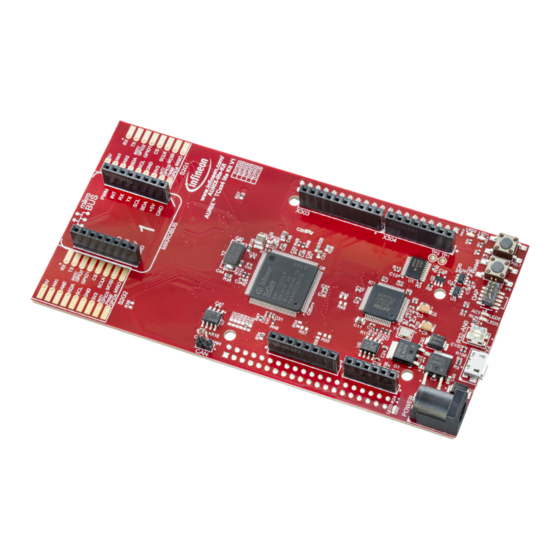
Page 7: Hardware Description
The following chapters give a detailed description of the board hardware and how it can be used. The different parts of the kit series are shown in Figure 2 and 3. 20 MHz Crystal Pin Connector X2 LED2 (green) LED1 (green) Infineon for AURIX P00.6 (low-active) P00.5 (low-active) Shield2Go Slot 1 Infineon... -
Page 8: Power Supply
User Manual AURIX™ TCxx4 lite Kit AURIX™ TCxx4 lite Kit 2 Hardware Description Power Supply The AURIX™ TCxx4 lite Kit must be supplied by an external DC power supply, this can be done via the DC plug X3 (recommended voltage range +7 V…+14 V) or via the Micro USB plug X4 (+5 V). The green Power LED4 indicates the presence of the generated 3.3 V supply voltage. -
Page 9: User Push Buttons, User Leds And Potentiometer
VDD_USB Pin Connector X2 +3V3 X303 X304 CAN Tranceiver Con. Potentiometer VDD_USB VEXT +3V3 AURIXä +3V3 TC3X4 or TC2X4 Micro Infineon Microcontroller IFX27001TFV33 S2G1/S2G2 On Board R39/0R_opt S2Go Slots miniWiggler U1 - U5 Infineon plug IFX27001TFV50 mikroBusä Optional +3V3 VEXT... -
Page 10: Debugging And On Board Miniwiggler
User Manual AURIX™ TCxx4 lite Kit AURIX™ TCxx4 lite Kit 2 Hardware Description Table 3 miniWiggler Pin Mapping for User LEDs Name miniWiggler Pin Color Active LED5 ADBUS4 (ACTIV) green Low-active (pull against GND) LED6 ADBUS7 (RUN) green Low-active (pull against GND) Table 4 AURIX™... -
Page 11: Miniwiggler Jds
The AURIX™ TCxx4 lite Kit provides a CAN interface via the CAN connector. The TLE9251V is the latest Infineon high-speed CAN transceiver generation, used inside HS CAN networks for automotive and also for industrial applications. It is designed to fulfill the requirements of ISO 11898-2 (2016) physical layer specification and respectively also the SAE standards J1939 and J2284. -
Page 12: Optional Cypress Semper™ (Secure) Flash
User Manual AURIX™ TCxx4 lite Kit AURIX™ TCxx4 lite Kit 2 Hardware Description Optional Cypress Semper™ (Secure) Flash The AURIX™ TCxx4 lite Kit provide the possibility to assemble an external flash. Usable devices are Cypress Semper™ NOR Flash Device Family S25HL and Cypress Semper™ Secure NOR Flash Device Family S35HL in SOIC-16 package. -
Page 13: Configuration
User Manual AURIX™ TCxx4 lite Kit AURIX™ TCxx4 lite Kit 3 Configuration Configuration Bootmode Table 6 User Startup Modes 1)2)3) HWCFG[5...3] Type of Boot Start-up mode is selected by Boot Mode Index Internal Start from Flash Alternate Boot Mode, Generic Bootstrap Loader on fail (P14.0/P14.1) Generic Bootstrap Loader (P14.0/P14.1) 1) The shadowed line indicates the default setting. -
Page 14: Optional Resistors
User Manual AURIX™ TCxx4 lite Kit AURIX™ TCxx4 lite Kit 3 Configuration Optional resistors Some resistors/bridges enable/disable or changing functions of specific signals in Table 8. To disable the signals, the resistors have to be removed. To enable, the resistor has to be assembled. For example: Desoldering the intialy assembled resistor R33, disables the Potentiometer and the analog Signal AN0 of the AURIX™, making it usable for other purposes. -
Page 15: Connector Pin Assignment
User Manual AURIX™ TCxx4 lite Kit AURIX™ TCxx4 lite Kit 4 Connector Pin Assignment Connector Pin Assignment Pinout of X1 and X2 connectors The pin headers X1 and X2 can be used to extend the evaluation board or to perform measurements on the AURIX™... -
Page 16: Shield2Go And Mikrobus™ Pinout
User Manual AURIX™ TCxx4 lite Kit AURIX™ TCxx4 lite Kit 4 Connector Pin Assignment Shield2Go and MikroBus™ Pinout The pin connectors for the Shield2Go Connectors 1 and 2 and the mikroBus™ can be used to extend the evaluation board or to perform measurements on the AURIX™ TC3X4/TC2X4. Figure shows the available signals at these connectors. -
Page 17: Arduino Compatible Connector
User Manual AURIX™ TCxx4 lite Kit AURIX™ TCxx4 lite Kit 4 Connector Pin Assignment Arduino Compatible Connector The mapping of GPIOs and AURIX™ pin functions to Arduino compatible functions can be found in Figure 7 Mapping of Arduino Functions to AURIX™ Pin Functions. The Arduino compatible connector supports SPI interface (SPI_xxx) •... -
Page 18: Infineon Dap Debug Connector (10-Pin)
4 Connector Pin Assignment Infineon DAP Debug Connector (10-pin) Infineon’s 10-pin Device Access Port Debug Connector (DAP) is a two-wire tool access port for microcontrollers and similar devices. It allows robust high-speed connections over a long cable for automotive applications. The pin assignment of the DAP Debug Connector is shown in Table 9. - Page 19 User Manual AURIX™ TCxx4 lite Kit AURIX™ TCxx4 lite Kit 4 Connector Pin Assignment Name AURIX™ Pin Direction Description on this signal to establish a logic one. The resistor shall not have a value less than 1 kOhms. Board Users Manual 19 of 27 Revision V1.1 2021-09-21...
-
Page 20: Schematics And Placement
User Manual AURIX™ TCxx4 lite Kit AURIX™ TCxx4 lite Kit 5 Schematics and Placement Schematics and Placement Figure 8 Schematic: Project Overview Board Users Manual 20 of 27 Revision V1.1 2021-09-21... - Page 21 User Manual AURIX™ TCxx4 lite Kit AURIX™ TCxx4 lite Kit 5 Schematics and Placement Figure 9 Schematic: On Board miniWiggler Board Users Manual 21 of 27 Revision V1.1 2021-09-21...
- Page 22 User Manual AURIX™ TCxx4 lite Kit AURIX™ TCxx4 lite Kit 5 Schematics and Placement Figure 10 Schematic: Power and Connectors Board Users Manual 22 of 27 Revision V1.1 2021-09-21...
- Page 23 User Manual AURIX™ TCxx4 lite Kit AURIX™ TCxx4 lite Kit 5 Schematics and Placement Figure 11 Schematic: CPU and config Board Users Manual 23 of 27 Revision V1.1 2021-09-21...
- Page 24 INT/ INT/ MOSI MOSI GPIO3 GPIO3 +3.3V PWM/ PWM/ MISO MISO GPIO4 GPIO4 S2G2 S2G1 MIKROBUS www.infineon.com/ AURIX-lite-Kit AURIX™ TCxx4 lite Kit V1 TC334 TC324 TC234 TC224 TC214 LED3 P00.6 ESR0 POWER Reset P00.5 -AN0 Figure 12 Placement: Top View...
- Page 25 User Manual AURIX™ TCxx4 lite Kit AURIX™ TCxx4 lite Kit 5 Schematics and Placement mikro RST/ RST/ GPIO2 GPIO2 GPIO1 GPIO1 MISO SCLK SCLK MOSI INT/ INT/ MOSI MOSI GPIO3 GPIO3 +3.3V PWM/ PWM/ MISO MISO GPIO4 GPIO4 S2G2 S2G1 +3V3 +3V3 P33.12...
-
Page 26: Revision History
User Manual AURIX™ TCxx4 lite Kit AURIX™ TCxx4 lite Kit Revision history Revision history Document Date of release Description of changes version V1.0 2021-08-06 Initial version V1.0 V1.1 2021-09-21 Page 17, Figure 7: Order on X301 corrected (mirrored) Board Users Manual 26 of 27 Revision V1.1 2021-09-21... -
Page 27: Disclaimer
WARNINGS 81726 Munich, Germany Due to technical requirements products may contain dangerous substances. For information on the types in question please contact your nearest Infineon © 2021 Infineon Technologies AG. Technologies office. All Rights Reserved. Except as otherwise explicitly approved by Infineon...
Need help?
Do you have a question about the AURIX TC 4 Series and is the answer not in the manual?
Questions and answers