Table of Contents
Advertisement
Quick Links
TLD5501-2QV Buck Demo
User Manual
About this document
Product description
The TLD5501-2QV is an AEC qualified dual channel buck DC-DC controller especially designed for high power
automotive applications:
•
Constant current (LED driver) and constant voltage regulation
•
EMC optimized device: Spread spectrum
•
Multiphase capability for voltage regulation
•
SPI interface to configure each channel's regulation and to read the diagnostic
•
Limp home function (fail-safe mode)
Scope and purpose
Scope of this user manual is to provide to the audience instructions on usage of the TLD5501-2 BUCK DEMO
evaluation board (schematic version V5.0, PCB version R2).
Intended audience
This document is intended for engineers who need to perform measurements and check performances with
TLD5501-2 BUCK DEMO evaluation board.
User Manual
www.infineon.com
Please read the Important Notice and Warnings at the end of this document
page 1 of 24
Rev.2.00
2021-04-12
Advertisement
Table of Contents

Related Manuals for Infineon TLD5501-2QV Buck Demo


Summary of Contents for Infineon TLD5501-2QV Buck Demo
-
Page 1: About This Document
TLD5501-2QV Buck Demo User Manual About this document Product description The TLD5501-2QV is an AEC qualified dual channel buck DC-DC controller especially designed for high power automotive applications: • Constant current (LED driver) and constant voltage regulation • EMC optimized device: Spread spectrum •... -
Page 2: Table Of Contents
About this document ........................1 Table of contents ........................2 Description ..........................3 Quick start procedure ......................4 Infineon μIO stick and Infineon Toolbox..................6 Install and launch Config Wizard ......................6 Board control with PC GUI ....................... 8 Basic user interface ..........................8 Engineering user interface ........................ -
Page 3: Description
User Manual Description Description The TLD5501-2QV BUCK DEMO is an evaluation board for high power applications with the TLD5501-2QV product. TLD5501-2QV is an AEC qualified dual channel buck DC-DC controller suitable for constant current (LED driver) and constant voltage applications. -
Page 4: Quick Start Procedure
Connect the power supply at the IN terminals (VIC and GND). Launch Infineon toolbox: refer to Chapter 4 to learn how to control the eval board with the PC GUI. The GUI is set by default for “Dual buck parallel voltage regulator”, thus for a constant voltage regulation set 100% of PWM duty cycle and then enable the PWM: it could be possible that an output over voltage (OV) or an output short to ground (S2G) is reported due to wrong RV1 and RV2 settings. - Page 5 User Manual Quick start procedure Output Voltage Infineon µIO connector Power supply Figure 2 TLD5501-2 BUCK DEMO configuration for “Dual buck parallel voltage regulator” application Figure 3 TLD5501-2 BUCK DEMO: Infineon µIO stick connection User Manual 5 of 24 Rev.2.00 2021-04-12...
-
Page 6: Infineon Μio Stick And Infineon Toolbox
4 Infineon μIO stick and Infineon Toolbox The Infineon μIO stick is an interface device for controlling Infineon boards/kits during run time through PC: Enables the communication between the evaluation board and the PC GUI via SPI using the Config •... - Page 7 User Manual Infineon μIO stick and Infineon Toolbox Figure 6 Install Config Wizard for LED Select “My Tools” tab on Infineon Toolbox Press “Start” on the config wizard for LED to start Figure 7 Start Config Wizard tool Click on TLD5501-2QV icon to start the LED GUI interface...
-
Page 8: Board Control With Pc Gui
TLD5501-2 BUCK DEMO evaluation board User Manual Board control with PC GUI 5 Board control with PC GUI The TLD5501-2QV PC GUI consists of 2 interfaces: • Basic user interface • Engineering user interface The GUI works only if the TLD5501-2 BUCK DEMO eval board is correctly connected to the μIO stick and properly supplied. -
Page 9: Engineering User Interface
TLD5501-2 BUCK DEMO evaluation board User Manual Board control with PC GUI In the “Digital Dimming” tab it is possible to configure the PWMI frequency and duty cycle. In Order to enable the DC-DC switching activity the PWM button need to be activated in ON state. On the “Diagnosis/Monitoring”... - Page 10 TLD5501-2 BUCK DEMO evaluation board User Manual Board control with PC GUI User Manual 10 of 24 Rev.2.00 2021-04-12...
-
Page 11: Operating Range And Power Derating
TLD5501-2 BUCK DEMO evaluation board User Manual Operating range and power derating Operating range and power derating The TLD5501-2 BUCK DEMO has very high efficiency, so it can deliver up to 40 W at the output on each channel without a heat sink at T = 25°C, V = 12 V I <... -
Page 12: Efficiency Measurements
TLD5501-2 BUCK DEMO evaluation board User Manual Efficiency Measurements Efficiency Measurements Efficiency of one channel in constant voltage regulation with a 1Ω load. Figure 12 TLD5501-2 BUCK DEMO: one channel efficiency measurements User Manual 12 of 24 Rev.2.00 2021-04-12... -
Page 13: Tld5501-2 Buck Demo Board Configuration
TLD5501-2 BUCK DEMO evaluation board User Manual TLD5501-2 BUCK DEMO board configuration 8 TLD5501-2 BUCK DEMO board configuration The default configuration of the evaluation board is “Dual buck parallel voltage regulator” in which the two channels work in multiphase to provide up to 80 W to the load with an efficiency above 90%. The board can be also configured for different scenarios: •... - Page 14 Connect the power supply at the IN terminals (VIC and GND). Launch Infineon toolbox: refer to Chapter 4 to learn how to control the eval board with the PC GUI. In the “Power Status Control” tab select the “2-ch regulator” to control each channel independently.
-
Page 15: Dual Buck Independent Current Regulators
TLD5501-2 BUCK DEMO evaluation board User Manual TLD5501-2 BUCK DEMO board configuration Dual buck independent current regulators In this configuration the two channels work as two independent constant current supply for LED applications. The following board configuration shall be applied: Open (green): SJP2-SJP3-SJP4-SJP5-SJP6-SJP7-SJP8-SJP9-SJP10 Populate (orange): R12-R13-R14-R18-R37-R38-R39-R44 Not-populate (red): R11-R16-R20-R21-R36-R43-R45-R46-C27-C37... - Page 16 User Manual TLD5501-2 BUCK DEMO board configuration Launch Infineon toolbox: refer to Chapter 4 to learn how to control the eval board with the PC GUI. In the “Power Status Control” tab select the “2-ch regulator” to control each channel independently.
-
Page 17: Single Buck Independent Current Regulator Plus Single Buck Independent Voltage Regulator
TLD5501-2 BUCK DEMO evaluation board User Manual TLD5501-2 BUCK DEMO board configuration Single buck independent current regulator plus single buck independent voltage regulator In this configuration one channel work as constant voltage supply and the other one as constant current supply (LED application). - Page 18 Connect the power supply at the IN terminals (VIC and GND). Launch Infineon toolbox: refer to Chapter 4 to learn how to control the eval board with the PC GUI. In the “Power Status Control” tab select the “2-ch regulator” to control each channel independently.
-
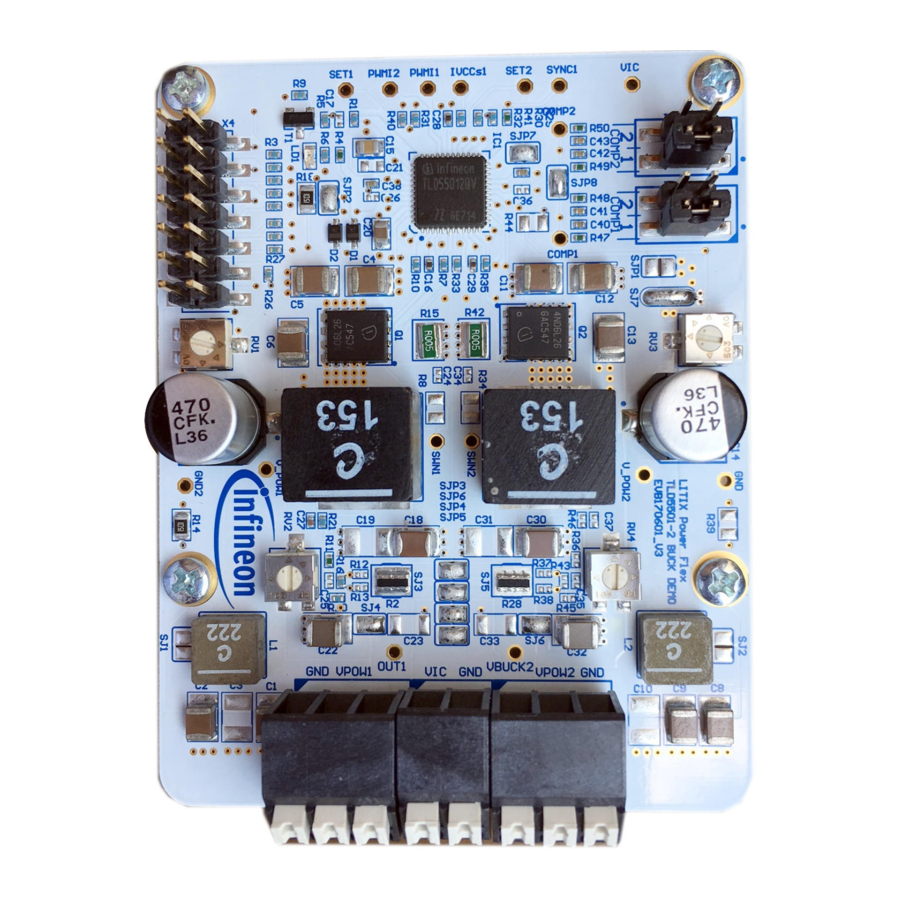
Page 19: Pcb - Component Placement
TLD5501-2 BUCK DEMO evaluation board User Manual PCB - component placement 9 PCB - component placement Figure 19 PCB component placement - top view User Manual 19 of 24 Rev.2.00 2021-04-12... -
Page 20: Schematic
TLD5501-2 BUCK DEMO evaluation board User Manual Schematic Schematic Figure 20 Schematic User Manual 20 of 24 Rev.2.00 2021-04-12... -
Page 21: Bill Of Material
TDK EPCOS C38, C39, C40, C42 22 nF TDK EPCOS C41, C43 10 nF TDK EPCOS D1, D2 BAT46WJ DIODES SBR0560S1Q-7 Infineon TLD5501-2QV L1, L2 2.2 µH Coilcraft XAL6030-222ME L3, L4 15 µH Coilcraft or XAL1010-153ME or SPM10065VT-150M-D LED 0603 red... - Page 22 TLD5501-2 BUCK DEMO evaluation board User Manual About this document Designator Value Manufacturer Part number RV2, RV4 10 kΩ TRIM Panasonic 30 V, 57 mΩ N-ch Infineon BSS306N User Manual 22 of 24 Rev.2.00 2021-04-12...
-
Page 23: Revision History
User Manual Revision history Revision history Document Date of release Description of changes version Rev. 1.00 2018-02-27 Initial User Manual Rev. 2.00 2021-04-12 Updated board to be connected to PC via Infineon µIO Stick User Manual 23 of 24 Rev.2.00 2021-04-12... - Page 24 With respect to any examples, hints or any typical 81726 München, Germany values stated herein and/or any information WARNINGS regarding the application of the product, Infineon Technologies hereby disclaims any and all Due to technical requirements products may contain warranties and liabilities of any kind, including dangerous substances.
Need help?
Do you have a question about the TLD5501-2QV Buck Demo and is the answer not in the manual?
Questions and answers