Table of Contents
Advertisement
Quick Links
UM_2305_PL88_2305_223554
Half-bridge buck converter evaluation board
using the EiceDRIVER™ 2EDL803x
Order code: EVAL_HB_2EDL803x-G3C, EVAL_HB_2EDL803x-G4B,
EVAL_HB_2EDL803x-G4C
About this document
Scope and purpose
The 2EDL803x is the EiceDRIVER™ family designed to drive both high-side and low-side MOSFETs in a half-
bridge configuration. The floating high-side driver is capable of driving a high-side MOSFET operating at up to
120 V bootstrap voltage. Version 4 provides full 4 A current capability, while version 3 provides 3 A. The high-
side bias voltage is generated using a bootstrap technique with an integrated bootstrap diode. The inputs of
the driver are TTL logic compatible and can withstand input common mode swing from -10 V up to 20 V.
Independent inputs allow controlling high- and low-side domains independently. Undervoltage lockout (UVLO)
on both high- and low-side supplies forces the corresponding outputs low in case of insufficient supply. The
2EDL803x is available in SON-8 pins 4 mm x 4 mm, SON-10 pins 4 mm x 4 mm, and SON-10 pins 3 mm x 3 mm
packages.
The half-bridge buck converter evaluation board described in this document is designed as a test platform for
evaluating the performance of 2EDL8034_G3C. For evaluation of different packages, evaluation boards are
available as shown in
Table 1
Board specifications
Part number
2EDL803x-G3C
2EDL803x-G4B
2EDL803x-G4C
Intended audience
Power supply designers, component engineers, hardware engineers, etc.
User Manual
www.infineon.com/2edl803x
Table
1.
Package
PG-VDSON-10-4
PG-VSON-8-5
PG-VDSON-10-2
Please read the Important Notice and Warnings at the end of this document
Body size
3 mm x 3 mm
4 mm x 4 mm
4 mm x 4 mm
page 1 of 19
z
Evaluation board
EVAL_HB_2EDL803x-G3C
EVAL_HB_2EDL803x-G4B
EVAL_HB_2EDL803x-G4C
2023-06-07
V 1.0
Advertisement
Table of Contents

Subscribe to Our Youtube Channel
Related Manuals for Infineon EiceDRIVER 2EDL803 Series


Summary of Contents for Infineon EiceDRIVER 2EDL803 Series
-
Page 1: About This Document
PG-VDSON-10-2 4 mm x 4 mm EVAL_HB_2EDL803x-G4C Intended audience Power supply designers, component engineers, hardware engineers, etc. User Manual Please read the Important Notice and Warnings at the end of this document V 1.0 www.infineon.com/2edl803x page 1 of 19 2023-06-07... -
Page 2: Table Of Contents
Half-bridge buck converter evaluation board using the EiceDRIVER™ 2EDL803x Table of contents Table of contents About this document ........................1 Table of contents ..........................2 Introduction .......................... 3 Getting started with the hardware ................... 4 Evaluation board ............................. 4 List of connection and test points ......................5 Quick start guide ............................. -
Page 3: Introduction
MOSFET’s switching behavior can also be evaluated. The board is configured as a half-bridge buck converter in an open-loop configuration and tested with 48 V typical input voltage and 12 V typical output voltage. The Infineon components used in this evaluation board are: EiceDRIVER™ 2EDL8034 as half-bridge driver for the low-side and high-side MOSFET •... -
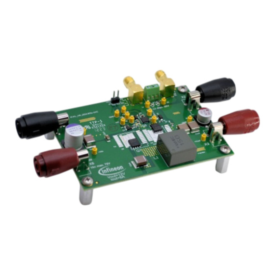
Page 4: Getting Started With The Hardware
Half-bridge buck converter evaluation board using the EiceDRIVER™ 2EDL803x Getting started with the hardware Getting started with the hardware Evaluation board Figure 2 EVAL_HB_2EDL803x – top side Figure 3 EVAL_HB_2EDL803x – bottom side User Manual 4 of 19 V 1.0 2023-06-07... -
Page 5: List Of Connection And Test Points
Half-bridge buck converter evaluation board using the EiceDRIVER™ 2EDL803x Getting started with the hardware List of connection and test points Table 3 Connection and test points – functional descriptions Connection/test point Description HI and LI PWM input Input GND connector connector Output GND connector... -
Page 6: Test Results
Half-bridge buck converter evaluation board using the EiceDRIVER™ 2EDL803x Test results Test results Figure 4 Figure 5 show the falling and rising propagation delay of the low-side and high-side drives with the V bias supplied and V = 48 V with no load on output. Figure 4 LI-LO falling (33.6 ns) and rising (34.7 ns) propagation delay (V = 12 V, V... - Page 7 Half-bridge buck converter evaluation board using the EiceDRIVER™ 2EDL803x Test results Figure 5 HI-HO falling (34.3 ns) and rising (33.5 ns) propagation delay (V = 12 V, V = 48 V, C load 4.1 nF) Figure 6 shows the high-side and low-side output waveforms together with the switch node waveforms at V 48 V, V = 12 V, duty = 23 percent, F = 200 kHz, load = 8 A, and T...
- Page 8 Half-bridge buck converter evaluation board using the EiceDRIVER™ 2EDL803x Test results Figure 6 LO (green), HO (pink), HS (yellow) waveforms User Manual 8 of 19 V 1.0 2023-06-07...
-
Page 9: Footprint Selection For Different Fets
Half-bridge buck converter evaluation board using the EiceDRIVER™ 2EDL803x Footprint selection for different FETs Footprint selection for different FETs The evaluation board allows the user to test the performance of the driver IC with different FETs available in various footprints. Table 4 lists all the footprints supported on this board. - Page 10 Half-bridge buck converter evaluation board using the EiceDRIVER™ 2EDL803x Footprint selection for different FETs Figure 9 PG-HSOF-8-1 package User Manual 10 of 19 V 1.0 2023-06-07...
- Page 11 Half-bridge buck converter evaluation board using the EiceDRIVER™ 2EDL803x Footprint selection for different FETs Figure 10 PG-HSOG-8-1 package Figure 11 PG-HDSOP-16-2 package User Manual 11 of 19 V 1.0 2023-06-07...
-
Page 12: Addendum
Half-bridge buck converter evaluation board using the EiceDRIVER™ 2EDL803x Addendum Addendum Schematic Figure 12 EVAL_HB_2EDL803x-G3C board schematic User Manual 12 of 19 V 1.0 2023-06-07... - Page 13 Half-bridge buck converter evaluation board using the EiceDRIVER™ 2EDL803x Addendum Figure 13 EVAL_HB_2EDL803x-G4B board schematic User Manual 13 of 19 V 1.0 2023-06-07...
- Page 14 Half-bridge buck converter evaluation board using the EiceDRIVER™ 2EDL803x Addendum Figure 14 EVAL_HB_2EDL803x-G4C board schematic User Manual 14 of 19 V 1.0 2023-06-07...
-
Page 15: Layout
Half-bridge buck converter evaluation board using the EiceDRIVER™ 2EDL803x Addendum Layout Figure 15 EVAL_HB_2EDL803x-G3C board layout Figure 16 EVAL_HB_2EDL803x-G4B board layout User Manual 15 of 19 V 1.0 2023-06-07... - Page 16 Half-bridge buck converter evaluation board using the EiceDRIVER™ 2EDL803x Addendum Figure 17 EVAL_HB_2EDL803x-G4C board layout User Manual 16 of 19 V 1.0 2023-06-07...
-
Page 17: Bill Of Materials (Bom)
Half-bridge buck converter evaluation board using the EiceDRIVER™ 2EDL803x Addendum Bill of materials (BOM) Figure 18 EVAL_HB_2EDL803x board BOM User Manual 17 of 19 V 1.0 2023-06-07... -
Page 18: Revision History
Half-bridge buck converter evaluation board using the EiceDRIVER™ 2EDL803x Revision history Revision history Document Date of release Description of changes version V 1.0 2023-06-07 Initial release User Manual 18 of 19 V 1.0 2023-06-07... - Page 19 Infineon Technologies hereby disclaims dangerous substances. For information on the types © 2023 Infineon Technologies AG. any and all warranties and liabilities of any kind in question please contact your nearest Infineon All Rights Reserved. (including without limitation warranties of non- Technologies office.
Need help?
Do you have a question about the EiceDRIVER 2EDL803 Series and is the answer not in the manual?
Questions and answers