Table of Contents
Advertisement
Quick Links
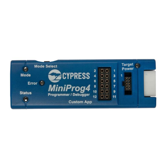
C Y 8 C K I T - 0 0 5 M i n i P r o g 4 P r o g r a m a n d D e b u g
Kit guide
About this document
Scope and purpose
This document serves as a guide for using the CY8CKIT-005 MiniProg4 Program and Debug Kit. The document
explains about the kit operation and technical description of the board.
Intended audience
For people who are interested to explore the functionality of MiniProg4.
User guide
Please read the sections "Important Notice" and "Warnings" at the end of this document
002-19782 Rev. *D
www.infineon.com
2023-10-18
Advertisement
Table of Contents

Related Manuals for Infineon CY8CKIT-005


Summary of Contents for Infineon CY8CKIT-005
-
Page 1: About This Document
Kit guide About this document Scope and purpose This document serves as a guide for using the CY8CKIT-005 MiniProg4 Program and Debug Kit. The document explains about the kit operation and technical description of the board. Intended audience For people who are interested to explore the functionality of MiniProg4. -
Page 2: Important Notice
Boards provided by Infineon Technologies. The design of the Evaluation Boards and Reference Boards has been tested by Infineon Technologies only as described in this document. The design is not qualified in terms of safety requirements, manufacturing and operation over the entire operating temperature range or lifetime. -
Page 3: Safety Precautions
CY8CKIT-005 MiniProg4 Program and Debug Kit guide Safety precautions Safety precautions Note: Please note the following warnings regarding the hazards associated with development system. Table 1 Safety precautions Caution: The evaluation or reference board contains parts and assemblies sensitive to electrostatic discharge (ESD). -
Page 4: Table Of Contents
CY8CKIT-005 MiniProg4 Program and Debug Kit guide Table of contents Table of contents About this document ............... . 1 Important notice . -
Page 5: Introduction
C, USB-SPI and USB-UART bridging functionality. The MiniProg4 provides a special feature enabling users to write their own custom firmware through the custom application mode. Note: The JTAG protocol for programming and debugging is supported only in CY8CKIT-005-A revision of Miniprog4. Figure 1... -
Page 6: Documentation Conventions
CY8CKIT-005 MiniProg4 Program and Debug Kit guide Introduction Documentation conventions Table 1 Document conventions for user guides Convention Usage Displays file locations, user-entered text, and source code: Courier New C:\...cd\icc\ Italics Displays file names and reference documentation: Read about the sourcefile.hex file in the PSoC™ Designer User Guide. -
Page 7: Installing Miniprog4
Follow the on-screen instructions to install the software. Each programming tool supports a subset of Infineon devices. See respective tool documentation for which device each supports. 2. Launch the PSoC™ Programmer or ModusToolbox™ Programming tools and connect the MiniProg4 to computer’s USB port using the provided USB cable. - Page 8 CY8CKIT-005 MiniProg4 Program and Debug Kit guide Installing MiniProg4 3. In PSoC™ Programmer, to connect to the port, in the Port Selection pane, click the MiniProg4 device. Click on Connect/Disconnect button as shown in Figure If the connection is successful, a status indicator in the lower-right corner of the PSoC™ Programmer window turns green and shows “Connected”.
- Page 9 CY8CKIT-005 MiniProg4 Program and Debug Kit guide Installing MiniProg4 In ModusToolbox™ Programming tools, to connect to the MiniProg4 probe, click Connect/Disconnect button as shown in Figure If the connection is successful, a status indicator in the lower-right corner of the ModusToolbox™ Programming tools window turns green and shows “Connected”.
-
Page 10: Miniprog4 Leds
CY8CKIT-005 MiniProg4 Program and Debug Kit guide Installing MiniProg4 MiniProg4 LEDs MiniProg4 has three indicator LEDs - Mode (Amber), Status (Green), and Error (Red) as shown in Figure Table 2 indicates the behavior of these LEDs for various operations. Figure 6... -
Page 11: Miniprog4 Buttons
CY8CKIT-005 MiniProg4 Program and Debug Kit guide Installing MiniProg4 MiniProg4 buttons MiniProg4 has two buttons that enable switching between various operating modes. Figure 7 shows the location of the buttons. In order to understand switching MiniProg4 modes, see Figure On power-up, MiniProg4 is in CMSIS-DAP/BULK mode by default. If the Mode Select button is pressed, MiniProg4 enters CMSIS-DAP/HID mode. -
Page 12: Technical Description
CY8CKIT-005 MiniProg4 Program and Debug Kit guide Technical description Technical description MiniProg4 is a protocol translation device. With MiniProg4, the PC host software can communicate through a USB port to the target device to be programmed or debugged, as shown in... -
Page 13: Interfaces
CY8CKIT-005 MiniProg4 Program and Debug Kit guide Technical description Interfaces 3.1.1 SWD/JTAG Arm®-based devices support the Serial Wire Debug (SWD) and JTAG protocols. The PSoC™ 4, PSoC™ 5LP, and PSoC™ 6 MCU device families implement these standards, which offers programming and debugging functions. -
Page 14: Connectors
CY8CKIT-005 MiniProg4 Program and Debug Kit guide Technical description Connectors 3.2.1 5-pin connector The 5-pin connector is configured as a single row with a 100-mil pitch. Suggested mating connector part number is Molex Connector Corporation 22-23-2051. SDAT SCLK XRES VTARG... -
Page 15: 6×2 Connector
CY8CKIT-005 MiniProg4 Program and Debug Kit guide Technical description Table 4 shows the summary of the protocols and related pin assignments. The pin mapping is also shown on the back of the MiniProg4 case. Table 4 Communication protocol pin assignments... -
Page 16: Power
CY8CKIT-005 MiniProg4 Program and Debug Kit guide Technical description Power MiniProg4 can be powered using the USB interface. On kits/boards where there is a single power supply for the entire board, MiniProg4 can supply power to the board. However, this supply is limited to approximately 200 mA, and is protected against excess current draw. -
Page 17: Appendix
CY8CKIT-005 MiniProg4 Program and Debug Kit guide Appendix Appendix Regulatory Compliance information The CY8KCIT-005 MiniProg4 Program and Debug Kit complies with the CE-Low Voltage Directive 2006/95/EC (Europe) safety requirement. It has been tested and verified to comply with the following electromagnetic compatibility (EMC) regulations. -
Page 18: Revision History
CY8CKIT-005 MiniProg4 Program and Debug Kit guide Revision history Revision history Document Date of release Description of changes version 2018-10-31 New kit guide. Updated “Installing MiniProg4” on Page Updated “MiniProg4 installation” on Page 2018-11-08 Updated description. Updated Figure 2019-05-24 Updated Copyright information. -
Page 19: Disclaimer
Technologies hereby disclaims any and all warranties authorized representatives of Infineon Technologies, and liabilities of any kind, including without limitation Infineon Technologies’ products may not be used in warranties of non-infringement of intellectual any applications where a failure of the product or any property rights of any third party.
Need help?
Do you have a question about the CY8CKIT-005 and is the answer not in the manual?
Questions and answers