
Subscribe to Our Youtube Channel
Related Manuals for Infineon XMC1400


Summary of Contents for Infineon XMC1400
- Page 1 XMC1400 CPU Card For XMC1000 Family CPU-14B-V1 XMC1400 CPU Card Board User's Manual Revision 2.0, 2019-09-16 Microcontroller...
- Page 2 Infineon Technologies components may be used in life-support devices or systems only with the express written approval of Infineon Technologies, if a failure of such components can reasonably be expected to cause the failure of that life-support device or system or to affect the safety or effectiveness of that device or system.
- Page 3 CPU-14B-V1 XMC1400 CPU Card Revision History Page or Item Subjects (major changes since previous revision) Revision 2.0, 2019-09-16 16,18 Change C210 to 4.7uF Trademarks of Infineon Technologies AG AURIXTM, C166TM, CanPAKTM, CIPOSTM, CIPURSETM, EconoPACKTM, CoolMOSTM, CoolSETTM, DI- POLTM, EasyPIMTM, EconoBRIDGETM, EconoDUALTM,...
-
Page 4: Table Of Contents
CPU-14B-V1 XMC1400 CPU Card Table of Contents Overview ............................Key Features ............................Block Diagram ............................ Hardware Description ........................XMC1400 connector for ARDUINO ................................8 2.1.1 Digital IO connector ..........................2.1.2 Analog input ............................2.1.3 Power connector, POWER ........................ 2.1.4 ICSP (In-Circuit Serial Programming) Header .................. - Page 5 Figure 7 LEDs Circuit ............................12 Figure 8 AD_AUX and AUX connector ........................12 Figure 9 Schematic 1 of 2 XMC1400 CPU Card for Arduino ................15 Figure 10 Schematic 2 of 2 XMC1400 CPU Card for Arduino ................16 Figure 11 XMC1400 CPU Card for Arduino layout and geometry ..............
- Page 6 Signals of ICSP connector ......................... 11 Table 6 LEDs Signal Description ........................12 Table 7 Signals of connector AD_AUX ......................13 Table 8 Signals of connector AUX ........................13 Table 9 XMC1400 CPU Card for Arduino ....................17 Board User's Manual Revision 2.0, 2019-09-16...
-
Page 7: Overview
Overview The XMC1400 CPU Card for Arduino has two rows of pin headers which fully compatible with Arduino shield. Hence, user can buy various Arduino shield boards off-the-shelf to test the capabilities of XMC1400 Microcontroller. Key Features The XMC1400 CPU Card for ArduinoTM is equipped with the following features •... -
Page 8: Xmc1400 Connector For Arduino
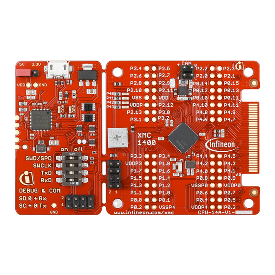
CPU-14B-V1 XMC1400 CPU Card Hardware Description The following sections give a detailed description of the hardware and how it can be used. Figure 2 XMC1400 CPU Card for Arduino XMC1400 connector for ARDUINO 2.1.1 Digital IO connector XMC1400 CPU Card for Arduino have 10 pin connector mounting holes and 8 pin connector mounting holes at IOH and IOL respectively. -
Page 9: Figure 3 Digital Io Connectors Ioh, Iol
CPU-14B-V1 XMC1400 CPU Card Figure 3 Digital IO connectors IOH, IOL Table 1 Digital IO of connector IOH Pin No. Signal Name XMC1400 Signal Name Description Arduino P2.0 C Clock P2.1 C Data / Address AREF P2.3 Analog reference voltage... -
Page 10: Analog Input
DC power jack. However, the DC power jack is not mounted. The XMC1400 device can operate by power supply of 1.8V till 5.5Vdc. On this board, 5Vdc is used to power the XMC1400 device. However, if user wants to power the XMC1400 device with 3.3Vdc, then, please remove R102 and solder 0 ohm resistor R101. -
Page 11: Icsp (In-Circuit Serial Programming) Header
CPU-14B-V1 XMC1400 CPU Card Figure 5 POWER connector Table 4 Pinout of the POWER connector Pin No. Arduino Signal Name XMC1400 Signal Name Description IOREF VDDP VDDP connect to 5V via R102 AREF P2.4 ADC input to sense Analog reference voltage 3.3V... -
Page 12: Other Connectors
Output ‘L ’ to on LED Other connectors board’s pinout XMC1400 microcontroller has more pins than is required Arduino s, those extra pins are group into connector AD_AUX (not mount) and AUX (not mount). Figure 8 AD_AUX and AUX connector Board User's Manual Revision 2.0, 2019-09-16... -
Page 13: Table 7 Signals Of Connector Ad_Aux
CPU-14B-V1 XMC1400 CPU Card Table 7 Signals of connector AD_AUX Pin No. Signal Name Description P2.2 ADC input ADC input P2.5 ADC input P2.7 ADC input P2.11 ADC input Table 8 Signals of connector AUX Pin No. Signal Name Description P0.5... -
Page 14: Production Data
CPU-14B-V1 XMC1400 CPU Card Production Data Schematics This chapter contains the schematics for the XMC1400 CPU Card for Arduino • Figure 9: CPU, Pin Headers, LED, Power Supply • Figure 10: On-board Debugger, Power Board User's Manual Revision 2.0, 2019-09-16... -
Page 17: Layout And Geometry
CPU-14B-V1 XMC1400 CPU Card Layout and Geometry Figure 11 XMC1400 CPU Card for Arduino layout and geometry Bill of Material Table 9 XMC1400 CPU Card for Arduino Reference Value Device Designator AD / n.m. PINHD-1X6 FIDUCIAL FIDUCIAL ADJ_301, ADJ_302, ADJ_303 AD_AUX / n.m. - Page 18 CPU-14B-V1 XMC1400 CPU Card Reference Value Device Designator 10uF/0805 C-EUC0805K C210 no ass./10nF/0402 C-EUC0402 C214 SS13B DIODE-SMB D101 IFX25001MEV33 IFX25001MEV33 IC101, IC201 IFX25001TFV50 IFX25001TFV50 IC102 LMV358MM LMV358MM IC103 XMC1400-T038 XMC1400-T038 IC104 SN74LVC2T45DCT SN74LVC2T45DCT IC202, IC205 SN74LVC1T45DCK SN74LVC1T45DCK IC203, IC204, IC206 IOH / n.m.
- Page 19 CPU-14B-V1 XMC1400 CPU Card Reference Value Device Designator LED-R/D/0603 LEDCHIPLED_0603 V202 BAT60A BAT60 V203 ESD_2CH_TSFP-3-1 ESD_2CH_TSFP-3-1 V204 DC21MMX / n.m. DC21MMX X101 Debug / m.n. MA04-2 X10² DEBUG / n.m. MA04-2 X201 ZX62-AB-5PA_MICRO- ZX62-AB-5PA X202 RESET / n.m. PINHD-1X1 X203 Board User's Manual Revision 2.0, 2019-09-16...
- Page 20 .i n f i n e o n . c o m Published by Infineon Technologies AG...
Need help?
Do you have a question about the XMC1400 and is the answer not in the manual?
Questions and answers